1,We Manufacturing processes are primarily classified into four types:
1:Forging,
2:Casting,
3:Cutting,
4:Rolling.
2,We can manufacture in accordance with these standards.
Standards:
GB Series (Chinese Standards), JB Series (Machinery Standards), HG Series (Chemical Industry Standards), ASME B16.5 (American Standards), BS4504 (British Standards), DIN (German Standards), and JIS (Japanese Standards).
Internationally, there are two primary systems of pipe flange standards: the European system, represented by the German DIN standards (including those of the former Soviet Union), and the American system, represented by the US ANSI pipe flange standards. Other common standards include: the Chinese Ministry of Machinery Industry standards (JB series), the Ministry of Chemical Industry standards (HG series), the Chinese National Standard *GB/T 9112–9124-2010 Steel Pipe Flanges*, as well as US standards (ASME B16.5), British standards (BS4504), German standards (DIN), Japanese standards (JIS), and marine standards (CBM), among others.
The nominal pressure ratings for the PN series are designated by "PN" and comprise the following nine levels: PN2.5, PN6, PN10, PN16, PN25, PN40, PN63, PN100, and PN160.
The nominal pressure ratings for the Class series are designated by "Class" and comprise the following six levels: Class150, Class300, Class600, Class900, Class1500, and Class2500.
Flange Classification
1. **According to Chemical Industry Standards:** Flanges are classified as follows:
Plate Flat Welding Flange (PL), Necked Flat Welding Flange (SO), Necked Butt Welding Flange (WN), Integral Flange (IF), Socket Welding Flange (SW), Threaded Flange (Th), Butt Welding Ring Loose Flange (PJ/SE), Blind Flange (BL), Flat Welding Ring Loose Flange (PJ/PJ), and Lined Blind Flange (BL(s)).
2. **According to Petrochemical (SH) Industry Standards:** Flanges are classified as follows:
Threaded Flange (PL), Butt Welding Flange (WN), Flat Welding Flange (SO), Socket Welding Flange (SW), Loose Flange (LJ), and Blind Flange (no specific designation).
3. **According to Machinery (JB) Industry Standards:** Flanges are classified as follows:
Integral Flange, Butt Welding Flange, Plate Flat Welding Flange, Butt Welding Ring Plate Loose Flange, Flat Welding Ring Plate Loose Flange, Lap Joint Ring Plate Loose Flange, and Blind Flange.
4. **According to Connection Method/Type:** Flanges are classified as follows:
Plate Flat Welding Flange, Necked Flat Welding Flange, Necked Butt Welding Flange, Socket Welding Flange, Threaded Flange, Blind Flange, Necked Butt Welding Ring Loose Flange, Flat Welding Ring Loose Flange, Ring-Type Joint (RTJ) Flange and Blind Flange, Large-Diameter Plate Flange, Large-Diameter High-Neck Flange, Figure-8 Blind Plate, Butt Welding Ring Loose Flange, etc.
5. **According to the Component Being Connected:** Flanges can be classified into Vessel Flanges and Pipe Flanges.
6. **According to Structural Type:** Flanges include Integral Flanges, Threaded Flanges, Flat Welding Flanges, Butt Welding Flanges, Lap Joint (Loose/Swivel) Flanges, and Blind Flanges.
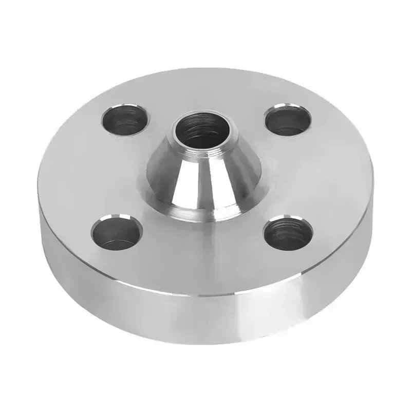
A flange—also referred to as a flange plate or rim—is a component used to connect shafts to one another, or, more commonly, to join the ends of pipes. Flanges are also utilized at the inlet and outlet ports of equipment to facilitate connections between two devices—for instance, the flange on a speed reducer. A "flange connection" or "flanged joint" refers to a detachable joint assembly comprising three interconnected elements—a flange, a gasket, and bolts—that together form a sealed structural unit. In the context of piping systems, a "pipe flange" specifically denotes a flange used for plumbing within the installation; when applied to equipment, it refers to the inlet or outlet flange of that specific device. Flanges feature a series of holes through which bolts are inserted to securely fasten the two flanges together, while a gasket placed between the flanges ensures a leak-proof seal. Flanges are broadly categorized into three types: threaded (screw-in) flanges, welded flanges, and clamp-type flanges. Flanges are invariably used in pairs; threaded flanges are suitable for low-pressure piping applications, whereas welded flanges are required for systems operating at pressures exceeding 4 kilograms per square centimeter. A sealing gasket is inserted between the two flange plates, which are then firmly secured using bolts. The thickness of a flange—as well as the specifications of the bolts used to fasten it—vary depending on the specific pressure rating required for the application. When connecting equipment such as water pumps or valves to piping systems, the corresponding connection points on these devices are often manufactured in the shape of a matching flange; this method of attachment is also referred to as a "flange connection." Generally, any connecting component that utilizes bolts to join and seal the perimeters of two flat surfaces—such as the joints in ventilation ducts—is termed a "flange"; such components may collectively be classified as "flange-type parts." However, since such a connection often constitutes merely a *portion* of a larger device—for instance, the interface between a flange and a water pump—it would be inappropriate to classify the entire water pump itself as a "flange-type part." Conversely, smaller components—such as valves—that feature such flanged interfaces may indeed be appropriately categorized as "flange-type parts."
-:-
For detailed product information, please contact sales.
-:
ASTM A841 HSLA Steel Flange, Thickness 65 to 100 mm (2.5 to 4 in.) Product Information
-:-
For detailed product information, please contact sales.
-:
ASTM A841 HSLA Steel Flange, Thickness 65 to 100 mm (2.5 to 4 in.) Synonyms
-:-
For detailed product information, please contact sales.
-:
ASTM A841 HSLA Steel, Thickness 65 to 100 mm (2.5 to 4 in.) Product Information
-:-
For detailed product information, please contact sales.
-:
# **Product Introduction: ASTM A841 HSLA Steel (Thickness 65-100 mm / 2.5-4 in.)**
**ASTM A841** is a **high-strength, low-alloy steel plate** specifically engineered and produced by the **Thermo-Mechanical Controlled Process (TMCP)**, representing a technological advancement for thick-section structural applications. In the **65-100 mm (2.5-4 in.) thickness range**, TMCP is critically leveraged to overcome the inherent metallurgical challenges of thick plates—namely, achieving uniform strength and toughness from surface to centerline without resorting to costly and distortive heat treatments. This grade is distinguished by its **exceptionally low carbon content and optimized microalloying**, which, combined with precise rolling and accelerated cooling, yield a fine-grained microstructure that delivers an outstanding balance of **high strength, excellent toughness, and superior weldability** in heavy plate applications.
---
## **International Standard & Key Specifications**
* **Primary Standard:** **ASTM A841/A841M** - Standard Specification for Steel Plates for Pressure Vessels, Produced by the Thermo-Mechanical Control Process (TMCP).
* **Core Mandate:** The **TMCP production route is not optional but a defining requirement** of this specification, ensuring a specific metallurgical state that differentiates it from conventionally rolled or normalized plates of equivalent grade.
* **Governing Standard:** **ASTM A6/A6M** - Standard Specification for General Requirements for Rolled Structural Steel Bars, Plates, Shapes, and Sheet Piling.
* **Key Related Standards:**
* **ASTM A20/A20M** - General Requirements for Pressure Vessel Plates (often invoked for testing).
* **ASTM A770** - Through-Thickness Tension Testing (commonly specified as a supplementary requirement for this thickness range).
* **AWS D1.1/D1.5** - Structural Welding Code.
* **Available Grades:** Typically produced to common yield strength levels such as 345 MPa (50 ksi) and 415 MPa (60 ksi). This overview is based on the prevalent **50 ksi** grade.
---
## **Chemical Composition (Weight %, max unless range is specified) - Grade 50**
The chemistry for thick TMCP plates is meticulously designed to ensure sufficient hardenability under slower centerline cooling while maintaining a very low carbon equivalent for weldability.
| Element | Composition Range / Limit (%) | Role in Thick-Section TMCP Performance |
| :--- | :--- | :--- |
| **Carbon (C)** | **0.07 - 0.12** | **Ultra-low** – Fundamental to achieving an extremely low Carbon Equivalent (CE), enabling crack-free welding with minimal preheat. It shifts the strengthening mechanism to microalloy precipitation and grain refinement. |
| **Manganese (Mn)** | **1.20 - 1.70** | Elevated compared to thinner plates to provide necessary hardenability and solid solution strengthening, compensating for slower cooling at mid-thickness. |
| **Phosphorus (P)** | 0.020 max | Impurity, stringently controlled. |
| **Sulfur (S)** | **0.005 max** | **Extra Low** – Critically minimized to maximize **through-thickness (Z-direction) ductility** and prevent lamellar tearing in highly restrained thick-plate welds. |
| **Silicon (Si)** | 0.15 - 0.50 | Deoxidizer. |
| **Columbium (Cb/Nb)** | **0.03 - 0.07** | **Primary TMCP microalloy.** Effectively pins austenite grain boundaries during controlled rolling, enabling the formation of an ultra-fine ferrite grain structure throughout the thickness. |
| **Vanadium (V)** | **0.04 - 0.09** | Works synergistically with Nb. Provides robust precipitation strengthening, which is especially crucial for maintaining yield strength at the plate's center. |
| **Titanium (Ti)** | 0.006 - 0.020 | Added for additional grain refinement and to control sulfide morphology (improves Z-properties). |
| **Nickel (Ni)** | **0.20 - 0.50 (optional)** | Often added in this thickness range to enhance hardenability and, more importantly, to significantly improve the low-temperature toughness at the mid-thickness. |
| **Molybdenum (Mo)** | 0.05 - 0.20 (optional) | May be added to increase hardenability and strength, particularly for 60 ksi grades. |
| **Carbon Equivalent (CE IIW)** | **Typically ≤ 0.40** | Remarkably low for this thickness and strength, a direct result of the TMCP alloy design. |
---
## **Typical Physical & Mechanical Properties (Grade 50, Thickness 65-100 mm)**
TMCP ensures property uniformity, but testing locations are carefully specified to represent the most conservative (slowest-cooled) region.
| Property | Value / Description | Test Location & Note |
| :--- | :--- | :--- |
| **Tensile Strength** | 485 - 620 MPa (70,000 - 90,000 psi) | **Mid-thickness (T/2)** |
| **Yield Strength (min)** | **345 MPa (50,000 psi)** | **Mid-thickness (T/2)** |
| **Elongation in 2-in (50 mm) (min)** | 20% | |
| **Charpy V-Notch Impact Toughness** | **Test Temp:** **-40°F / -40°C** (or lower per spec). **Min. Avg. Energy:** **27 J (20 ft·lbf)** or higher. | **Quarter-thickness (T/4)**. The standard location, as toughness at T/2 is inherently lower but controlled by the T/4 requirement. |
| **Through-Thickness Reduction of Area (Z%)** | **When specified per ASTM A770:** Minimum **25-30%** is typical. | **Supplementary Requirement S1 is strongly recommended** for critical applications. The low sulfur content inherently supports high values. |
| **Weldability (Pcm / CE)** | **Pcm typically < 0.22** | Allows for **significantly lower preheat temperatures** compared to normalized steels of equivalent thickness and strength, often by 100°C or more. |
| **Brinell Hardness** | 180 - 220 HBW (surface) | Slight gradient to center is normal but minimal compared to conventional steel. |
---
## **Product Applications**
ASTM A841 in the 65-100 mm range is specified for the most critical, heavily welded structural nodes and primary load-bearing members where conventional steels would pose significant fabrication challenges or performance limitations.
**Primary Industries and Structures:**
1. **Mega-Scale Mining & Heavy Equipment:**
* **Main frames, propel cases, and revolving frames** for ultra-class hydraulic excavators and walking draglines.
* **Chassis and body frames** for 400-ton+ haul trucks.
* **Critical weldments** in large tunnel boring machines.
2. **Offshore & Marine Engineering:**
* **Node joints, tubular joints, and stiffeners** in fixed offshore platforms (jackets).
* **Hull plates and structural members** for icebreakers and polar-class vessels.
* **Components** for floating production storage and offloading (FPSO) vessels.
3. **Civil Infrastructure:**
* **Box girder webs and flanges** for long-span bridges.
* **Gusset plates and connection zones** in major arch or cable-stayed bridges.
* **Penstocks and surge chambers** for hydroelectric power plants.
4. **Pressure Vessels & Heavy Industry:**
* **Thick-walled reactors and separators** in petrochemical and gas processing industries.
* **Hydraulic press frames** and **mill housings**.
---
## **Advantages and Critical Fabrication Considerations**
* **Advantages:**
* **Transformational Weldability:** The very low CE enables **dramatic reductions in preheat requirements**, drastically cutting fabrication energy costs, improving working conditions, and reducing distortion and residual stresses.
* **Superior Through-Thickness Properties:** Excellent Z-direction ductility (due to low S) minimizes the risk of lamellar tearing in complex, restrained thick-plate connections.
* **Exceptional Toughness Consistency:** TMCP provides better toughness uniformity from surface to center than normalized thick plate, enhancing structural reliability.
* **No Post-Rolling Heat Treatment:** Eliminates the cost, time, and distortion associated with normalizing thick plates.
* **Critical Fabrication Considerations:**
* **Heat Input Management:** **Strict adherence to maximum heat input limits is crucial.** Excessive heat input can create an overly tempered, softened region in the HAZ of the TMCP base metal. A qualified Welding Procedure Specification (WPS) is mandatory.
* **Z-Direction Testing:** For any highly restrained joint (e.g., T-joints in nodes), specifying **ASTM A770 Supplementary Requirement S1** is considered **essential**, not optional.
* **Thermal Cutting:** **Preheat is still required for flame cutting** edges, especially those to be welded, to prevent hydrogen uptake and under-bead cracking. Plasma or laser cutting is preferred.
* **Welding Consumables:** Must use **ultra-low hydrogen (ULH)** consumables. Filler metal selection should consider notch toughness matching for the service environment.
* **No Re-Normalizing:** The steel's properties are irrevocably tied to the TMCP cycle. Any post-fabrication full heat treatment (e.g., stress relieving at very high temperatures) must be evaluated with the steel producer, as it can alter properties.
**In summary, ASTM A841 in the 65-100 mm thickness range represents the pinnacle of modern plate steel technology for heavy welded construction. It solves the traditional thick-plate dilemma of choosing between weldability and performance by offering both. Its use signifies a commitment to advanced engineering, enabling safer, more efficient, and more reliable fabrication of the world's most massive and critical structures.**
-:-
For detailed product information, please contact sales.
-:
ASTM A841 HSLA Steel, Thickness 65 to 100 mm (2.5 to 4 in.) Specification
Dimensions
Size:
Diameter 20-1000 mm Length <4546 mm
Size:We can customized as required
Standard:
Per your request or drawing
We can customized as required
Properties(Theoretical)
Chemical Composition
-:-
For detailed product information, please contact sales.
-:
ASTM A841 HSLA Steel, Thickness 65 to 100 mm (2.5 to 4 in.) Properties
-:-
For detailed product information, please contact sales.
-:
Applications of ASTM A841 HSLA Steel Flange, Thickness 65 to 100 mm (2.5 to 4 in.)
-:-
For detailed product information, please contact sales.
-:
Chemical Identifiers ASTM A841 HSLA Steel Flange, Thickness 65 to 100 mm (2.5 to 4 in.)
-:-
For detailed product information, please contact sales.
-:
Packing of ASTM A841 HSLA Steel Flange, Thickness 65 to 100 mm (2.5 to 4 in.)
-:-
For detailed product information, please contact sales.
-:
Standard Packing:
-:-
For detailed product information, please contact sales.
-:
Typical bulk packaging includes palletized plastic 5 gallon/25 kg. pails, fiber and Steel Flange drums to 1 ton super sacks in full container (FCL) or truck load (T/L) quantities. Research and sample quantities and hygroscopic, oxidizing or other air sensitive materials may be packaged under argon or vacuum. Solutions are packaged in polypropylene, plastic or glass jars up to palletized 1017 gallon liquid totes Special package is available on request. E FORUs’ is carefully handled to minimize damage during storage and transportation and to preserve the quality of our products in their original condition