1,We Manufacturing processes are primarily classified into four types:
1:Forging,
2:Casting,
3:Cutting,
4:Rolling.
2,We can manufacture in accordance with these standards.
Standards:
GB Series (Chinese Standards), JB Series (Machinery Standards), HG Series (Chemical Industry Standards), ASME B16.5 (American Standards), BS4504 (British Standards), DIN (German Standards), and JIS (Japanese Standards).
Internationally, there are two primary systems of pipe flange standards: the European system, represented by the German DIN standards (including those of the former Soviet Union), and the American system, represented by the US ANSI pipe flange standards. Other common standards include: the Chinese Ministry of Machinery Industry standards (JB series), the Ministry of Chemical Industry standards (HG series), the Chinese National Standard *GB/T 9112–9124-2010 Steel Pipe Flanges*, as well as US standards (ASME B16.5), British standards (BS4504), German standards (DIN), Japanese standards (JIS), and marine standards (CBM), among others.
The nominal pressure ratings for the PN series are designated by "PN" and comprise the following nine levels: PN2.5, PN6, PN10, PN16, PN25, PN40, PN63, PN100, and PN160.
The nominal pressure ratings for the Class series are designated by "Class" and comprise the following six levels: Class150, Class300, Class600, Class900, Class1500, and Class2500.
Flange Classification
1. **According to Chemical Industry Standards:** Flanges are classified as follows:
Plate Flat Welding Flange (PL), Necked Flat Welding Flange (SO), Necked Butt Welding Flange (WN), Integral Flange (IF), Socket Welding Flange (SW), Threaded Flange (Th), Butt Welding Ring Loose Flange (PJ/SE), Blind Flange (BL), Flat Welding Ring Loose Flange (PJ/PJ), and Lined Blind Flange (BL(s)).
2. **According to Petrochemical (SH) Industry Standards:** Flanges are classified as follows:
Threaded Flange (PL), Butt Welding Flange (WN), Flat Welding Flange (SO), Socket Welding Flange (SW), Loose Flange (LJ), and Blind Flange (no specific designation).
3. **According to Machinery (JB) Industry Standards:** Flanges are classified as follows:
Integral Flange, Butt Welding Flange, Plate Flat Welding Flange, Butt Welding Ring Plate Loose Flange, Flat Welding Ring Plate Loose Flange, Lap Joint Ring Plate Loose Flange, and Blind Flange.
4. **According to Connection Method/Type:** Flanges are classified as follows:
Plate Flat Welding Flange, Necked Flat Welding Flange, Necked Butt Welding Flange, Socket Welding Flange, Threaded Flange, Blind Flange, Necked Butt Welding Ring Loose Flange, Flat Welding Ring Loose Flange, Ring-Type Joint (RTJ) Flange and Blind Flange, Large-Diameter Plate Flange, Large-Diameter High-Neck Flange, Figure-8 Blind Plate, Butt Welding Ring Loose Flange, etc.
5. **According to the Component Being Connected:** Flanges can be classified into Vessel Flanges and Pipe Flanges.
6. **According to Structural Type:** Flanges include Integral Flanges, Threaded Flanges, Flat Welding Flanges, Butt Welding Flanges, Lap Joint (Loose/Swivel) Flanges, and Blind Flanges.
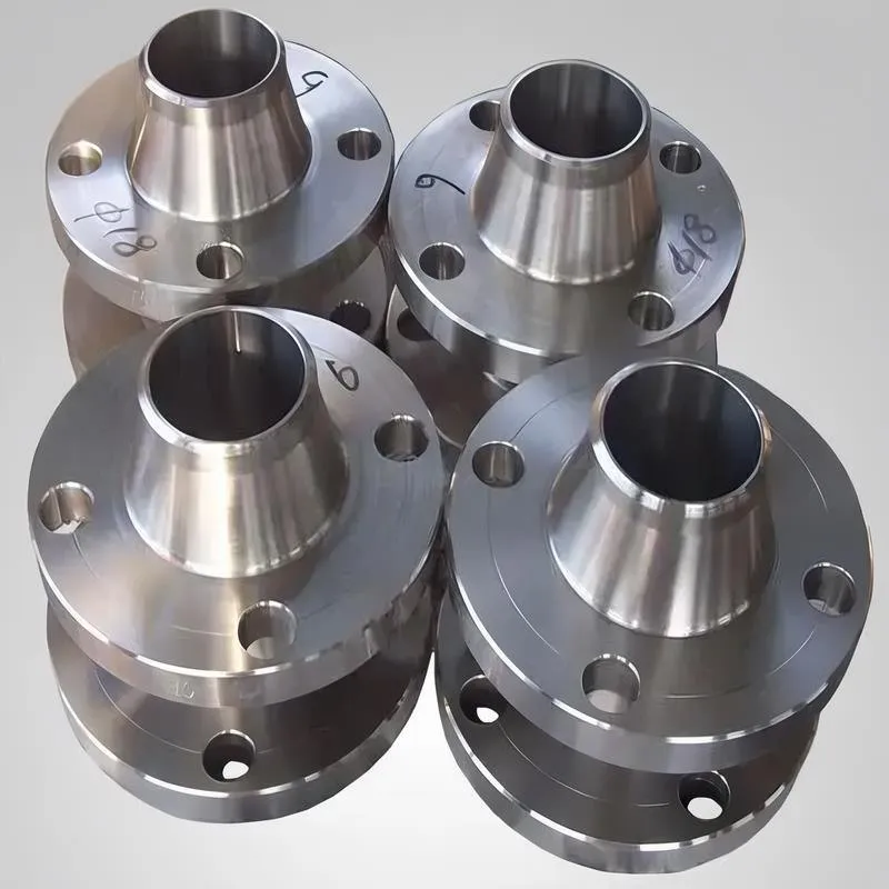
A flange—also referred to as a flange plate or rim—is a component used to connect shafts to one another, or, more commonly, to join the ends of pipes. Flanges are also utilized at the inlet and outlet ports of equipment to facilitate connections between two devices—for instance, the flange on a speed reducer. A "flange connection" or "flanged joint" refers to a detachable joint assembly comprising three interconnected elements—a flange, a gasket, and bolts—that together form a sealed structural unit. In the context of piping systems, a "pipe flange" specifically denotes a flange used for plumbing within the installation; when applied to equipment, it refers to the inlet or outlet flange of that specific device. Flanges feature a series of holes through which bolts are inserted to securely fasten the two flanges together, while a gasket placed between the flanges ensures a leak-proof seal. Flanges are broadly categorized into three types: threaded (screw-in) flanges, welded flanges, and clamp-type flanges. Flanges are invariably used in pairs; threaded flanges are suitable for low-pressure piping applications, whereas welded flanges are required for systems operating at pressures exceeding 4 kilograms per square centimeter. A sealing gasket is inserted between the two flange plates, which are then firmly secured using bolts. The thickness of a flange—as well as the specifications of the bolts used to fasten it—vary depending on the specific pressure rating required for the application. When connecting equipment such as water pumps or valves to piping systems, the corresponding connection points on these devices are often manufactured in the shape of a matching flange; this method of attachment is also referred to as a "flange connection." Generally, any connecting component that utilizes bolts to join and seal the perimeters of two flat surfaces—such as the joints in ventilation ducts—is termed a "flange"; such components may collectively be classified as "flange-type parts." However, since such a connection often constitutes merely a *portion* of a larger device—for instance, the interface between a flange and a water pump—it would be inappropriate to classify the entire water pump itself as a "flange-type part." Conversely, smaller components—such as valves—that feature such flanged interfaces may indeed be appropriately categorized as "flange-type parts."
-:-
For detailed product information, please contact sales.
-:
AISI 1038 Steel Flange, cold drawn, 19-32 mm (0.75-1.25 in) round Product Information
-:-
For detailed product information, please contact sales.
-:
AISI 1038 Steel Flange, cold drawn, 19-32 mm (0.75-1.25 in) round Synonyms
-:-
For detailed product information, please contact sales.
-:
AISI 1038 Steel, cold drawn, 19-32 mm (0.75-1.25 in) round Product Information
-:-
For detailed product information, please contact sales.
-:
### **Technical Data Sheet: AISI 1038 Steel - Cold Drawn Round Bars (19-32 mm / 0.75-1.25 in)**
---
#### **1. Product Overview**
AISI 1038 cold drawn round bars are medium-carbon steel products processed through cold drawing to achieve enhanced mechanical properties, improved dimensional accuracy, and superior surface finish. This grade features a slightly higher carbon content than AISI 1035, combined with elevated manganese levels, providing better hardenability and strength. The cold working process results in significant strain hardening, making this material ideal for precision components requiring high strength-to-weight ratios and reliable performance in demanding applications. The 19-32 mm (0.75-1.25 in) diameter range is particularly popular for general mechanical and automotive applications.
---
#### **2. Key Characteristics & Advantages**
- **Enhanced Strength Properties:** Cold working increases yield strength by 30-45% compared to hot-rolled material
- **Superior Dimensional Control:** Maintains tight diameter tolerances (±0.075 mm / ±0.003 in typical)
- **Excellent Surface Quality:** Produces smooth, scale-free surface (1.6-3.2 µm Ra) suitable for bearing surfaces
- **Improved Hardenability:** Higher carbon and manganese content provides better response to heat treatment
- **Good Machinability:** Consistent machining characteristics in cold worked condition
- **Better Straightness:** Essential for rotating components and precision assemblies
- **Cost-Effective Performance:** Provides high strength without alloying element costs
---
#### **3. Chemical Composition**
| Element | Composition Range (%) | Standard Reference |
|---------|----------------------|-------------------|
| **Carbon (C)** | 0.35 - 0.42 | ASTM A108 / SAE J403 |
| **Manganese (Mn)** | 0.70 - 1.00 | ASTM A108 / SAE J403 |
| **Phosphorus (P)** | ≤ 0.040 | ASTM A108 / SAE J403 |
| **Sulfur (S)** | ≤ 0.050 | ASTM A108 / SAE J403 |
| **Silicon (Si)** | 0.15 - 0.35 | ASTM A108 / SAE J403 |
| **Iron (Fe)** | Balance | - |
*Note: Some specifications may allow manganese up to 1.05% maximum.*
---
#### **4. Typical Mechanical Properties (Cold Drawn Condition)**
| Property | Value Range | Test Standard |
|----------|-------------|---------------|
| **Tensile Strength** | 620 - 760 MPa (90 - 110 ksi) | ASTM A370 |
| **Yield Strength (0.2% offset)** | 515 - 655 MPa (75 - 95 ksi) | ASTM A370 |
| **Elongation in 50 mm (2")** | 12% - 17% | ASTM A370 |
| **Reduction of Area** | 35% - 45% | ASTM A370 |
| **Brinell Hardness** | 197 - 255 HB | ASTM E10 |
| **Surface Roughness (Ra)** | 1.6 - 3.2 µm (63 - 125 µin) | ASME B46.1 |
| **Modulus of Elasticity** | 200 GPa (29,000 ksi) | ASTM E111 |
| **Shear Modulus** | 80 GPa (11,600 ksi) | ASTM E143 |
| **Poisson's Ratio** | 0.29 | ASTM E132 |
| **Density** | 7.87 g/cm³ (0.284 lb/in³) | - |
| **Machinability Rating** | ~45% (relative to 1212 steel) | - |
---
#### **5. Physical & Thermal Properties**
| Property | Value |
|----------|-------|
| **Thermal Conductivity** | 50.2 W/m·K (34.8 BTU·in/hr·ft²·°F) |
| **Specific Heat Capacity** | 486 J/kg·K (0.116 BTU/lb·°F) |
| **Coefficient of Thermal Expansion** | 11.3 µm/m·°C (6.3 µin/in·°F) 20-100°C |
| **Electrical Resistivity** | 0.190 µΩ·m |
| **Magnetic Properties** | Ferromagnetic |
| **Melting Point** | 1480 - 1520°C (2696 - 2768°F) |
---
#### **6. International Standard Equivalents**
| Standard System | Designation | Primary Specification |
|----------------|-------------|----------------------|
| **UNS** | G10380 | Unified Numbering System |
| **SAE/AISI** | 1038 | SAE J403 |
| **ASTM** | Grade 1038 | ASTM A108 (Cold-Finished) |
| **EN (Europe)** | 1.1156 (C38E) | EN 10083-2 |
| **ISO** | C38E | ISO 683-18 |
| **JIS (Japan)** | S38C | JIS G4051 |
| **GB (China)** | 40# (40钢) | GB/T 699 |
| **DIN (Germany)** | 1.1156, Ck38 | DIN 17200 |
---
#### **7. Heat Treatment Response**
AISI 1038 responds well to various heat treatments, with its composition providing good hardenability:
**Recommended Parameters:**
- **Annealing:** 790-815°C (1450-1500°F), slow cool (furnace cool preferred)
- **Normalizing:** 870-925°C (1600-1700°F), air cool
- **Quenching:** 830-855°C (1525-1575°F), oil quench recommended
- **Tempering:** 425-650°C (800-1200°F) depending on required properties
**Hardenability Data (Typical):**
- Jominy distance to 50 HRC: Approximately 8-12 mm from quenched end
- Maximum achievable hardness: 55-58 HRC (as-quenched)
- Typical tempered hardness: 28-40 HRC depending on tempering temperature
---
#### **8. Primary Applications**
Cold drawn AISI 1038 rounds are specified for components requiring high strength, good wear resistance, and dimensional accuracy:
**Automotive Components:**
- Axle shafts and drive shafts
- Transmission gears and shafts
- Steering system components
- Suspension linkage parts
- Brake system components
**Industrial Machinery:**
- High-strength shafts and spindles
- Gear blanks and sprockets
- Hydraulic piston rods
- Pump shafts and motor shafts
- Machine tool components
**Construction & Agricultural:**
- Implement drive shafts
- PTO shafts
- Excavator pins and bushings
- Heavy equipment components
- High-strength fasteners
**General Manufacturing:**
- Precision pins and dowels
- Tool holders and fixtures
- Bearing races and sleeves
- Valve stems and actuator rods
- Wear-resistant components
---
#### **9. Fabrication & Processing**
**Machining Operations:**
- Requires rigid setups and proper tooling
- Recommended cutting speeds: 30-45 m/min (100-150 ft/min)
- Carbide tools with positive rake angles preferred
- Use cutting fluids for improved tool life and surface finish
- Annealing (if needed) improves machinability for complex parts
**Welding Considerations:**
- Pre-heating (150-260°C/300-500°F) mandatory
- Low-hydrogen electrodes (E7018, E8018) required
- Post-weld heat treatment (595-650°C/1100-1200°F) strongly recommended
- Limited weldability due to carbon content and cold worked structure
**Forming & Bending:**
- Moderate cold forming capability with proper radii
- Minimum bend radius: 3 times material thickness
- Hot forming recommended for complex shapes
- Stress relieving advised after severe forming
---
#### **10. Quality Assurance**
- Certified mill test reports including chemical analysis
- Mechanical property certification to ASTM A108
- Dimensional inspection per ASTM A108 Table A1.1
- Surface finish verification
- Straightness tolerance: ≤0.25 mm per 300 mm (≤0.010 in per foot)
- Optional NDT testing available (ultrasonic, magnetic particle)
- Standard lengths: 3-6 meters (10-20 feet)
---
#### **11. Storage & Handling**
- Store in dry conditions to prevent corrosion
- Protect surfaces from physical damage
- Use proper lifting equipment
- Stack on flat, level supports
- Implement inventory rotation (FIFO)
---
**Important Considerations:**
1. **Anisotropy:** Cold drawn bars exhibit directional properties
2. **Stress Relief:** Recommended after heavy machining or forming
3. **Heat Treatment Planning:** Consider final treatment before machining
4. **Weldability:** Limited - consider alternative joining methods
5. **Quality Verification:** Review test reports for critical applications
6. **Section Size Effects:** Properties may vary with diameter
---
**Disclaimer:** This technical specification provides general information. Actual properties may vary based on manufacturer and processing. For engineering applications, consult official specifications and conduct appropriate testing. Professional engineering judgment should be applied for critical applications.
-:-
For detailed product information, please contact sales.
-:
AISI 1038 Steel, cold drawn, 19-32 mm (0.75-1.25 in) round Specification
Dimensions
Size:
Diameter 20-1000 mm Length <4797 mm
Size:We can customized as required
Standard:
Per your request or drawing
We can customized as required
Properties(Theoretical)
Chemical Composition
-:-
For detailed product information, please contact sales.
-:
AISI 1038 Steel, cold drawn, 19-32 mm (0.75-1.25 in) round Properties
-:-
For detailed product information, please contact sales.
-:
Applications of AISI 1038 Steel Flange, cold drawn, 19-32 mm (0.75-1.25 in) round
-:-
For detailed product information, please contact sales.
-:
Chemical Identifiers AISI 1038 Steel Flange, cold drawn, 19-32 mm (0.75-1.25 in) round
-:-
For detailed product information, please contact sales.
-:
Packing of AISI 1038 Steel Flange, cold drawn, 19-32 mm (0.75-1.25 in) round
-:-
For detailed product information, please contact sales.
-:
Standard Packing:
-:-
For detailed product information, please contact sales.
-:
Typical bulk packaging includes palletized plastic 5 gallon/25 kg. pails, fiber and Steel Flange drums to 1 ton super sacks in full container (FCL) or truck load (T/L) quantities. Research and sample quantities and hygroscopic, oxidizing or other air sensitive materials may be packaged under argon or vacuum. Solutions are packaged in polypropylene, plastic or glass jars up to palletized 1268 gallon liquid totes Special package is available on request. E FORUs’ is carefully handled to minimize damage during storage and transportation and to preserve the quality of our products in their original condition