1,We Manufacturing processes are primarily classified into four types:
1:Forging,
2:Casting,
3:Cutting,
4:Rolling.
2,We can manufacture in accordance with these standards.
Standards:
GB Series (Chinese Standards), JB Series (Machinery Standards), HG Series (Chemical Industry Standards), ASME B16.5 (American Standards), BS4504 (British Standards), DIN (German Standards), and JIS (Japanese Standards).
Internationally, there are two primary systems of pipe flange standards: the European system, represented by the German DIN standards (including those of the former Soviet Union), and the American system, represented by the US ANSI pipe flange standards. Other common standards include: the Chinese Ministry of Machinery Industry standards (JB series), the Ministry of Chemical Industry standards (HG series), the Chinese National Standard *GB/T 9112–9124-2010 Steel Pipe Flanges*, as well as US standards (ASME B16.5), British standards (BS4504), German standards (DIN), Japanese standards (JIS), and marine standards (CBM), among others.
The nominal pressure ratings for the PN series are designated by "PN" and comprise the following nine levels: PN2.5, PN6, PN10, PN16, PN25, PN40, PN63, PN100, and PN160.
The nominal pressure ratings for the Class series are designated by "Class" and comprise the following six levels: Class150, Class300, Class600, Class900, Class1500, and Class2500.
Flange Classification
1. **According to Chemical Industry Standards:** Flanges are classified as follows:
Plate Flat Welding Flange (PL), Necked Flat Welding Flange (SO), Necked Butt Welding Flange (WN), Integral Flange (IF), Socket Welding Flange (SW), Threaded Flange (Th), Butt Welding Ring Loose Flange (PJ/SE), Blind Flange (BL), Flat Welding Ring Loose Flange (PJ/PJ), and Lined Blind Flange (BL(s)).
2. **According to Petrochemical (SH) Industry Standards:** Flanges are classified as follows:
Threaded Flange (PL), Butt Welding Flange (WN), Flat Welding Flange (SO), Socket Welding Flange (SW), Loose Flange (LJ), and Blind Flange (no specific designation).
3. **According to Machinery (JB) Industry Standards:** Flanges are classified as follows:
Integral Flange, Butt Welding Flange, Plate Flat Welding Flange, Butt Welding Ring Plate Loose Flange, Flat Welding Ring Plate Loose Flange, Lap Joint Ring Plate Loose Flange, and Blind Flange.
4. **According to Connection Method/Type:** Flanges are classified as follows:
Plate Flat Welding Flange, Necked Flat Welding Flange, Necked Butt Welding Flange, Socket Welding Flange, Threaded Flange, Blind Flange, Necked Butt Welding Ring Loose Flange, Flat Welding Ring Loose Flange, Ring-Type Joint (RTJ) Flange and Blind Flange, Large-Diameter Plate Flange, Large-Diameter High-Neck Flange, Figure-8 Blind Plate, Butt Welding Ring Loose Flange, etc.
5. **According to the Component Being Connected:** Flanges can be classified into Vessel Flanges and Pipe Flanges.
6. **According to Structural Type:** Flanges include Integral Flanges, Threaded Flanges, Flat Welding Flanges, Butt Welding Flanges, Lap Joint (Loose/Swivel) Flanges, and Blind Flanges.
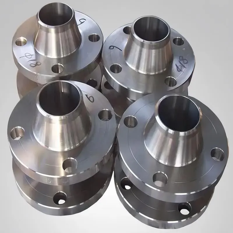
A flange—also referred to as a flange plate or rim—is a component used to connect shafts to one another, or, more commonly, to join the ends of pipes. Flanges are also utilized at the inlet and outlet ports of equipment to facilitate connections between two devices—for instance, the flange on a speed reducer. A "flange connection" or "flanged joint" refers to a detachable joint assembly comprising three interconnected elements—a flange, a gasket, and bolts—that together form a sealed structural unit. In the context of piping systems, a "pipe flange" specifically denotes a flange used for plumbing within the installation; when applied to equipment, it refers to the inlet or outlet flange of that specific device. Flanges feature a series of holes through which bolts are inserted to securely fasten the two flanges together, while a gasket placed between the flanges ensures a leak-proof seal. Flanges are broadly categorized into three types: threaded (screw-in) flanges, welded flanges, and clamp-type flanges. Flanges are invariably used in pairs; threaded flanges are suitable for low-pressure piping applications, whereas welded flanges are required for systems operating at pressures exceeding 4 kilograms per square centimeter. A sealing gasket is inserted between the two flange plates, which are then firmly secured using bolts. The thickness of a flange—as well as the specifications of the bolts used to fasten it—vary depending on the specific pressure rating required for the application. When connecting equipment such as water pumps or valves to piping systems, the corresponding connection points on these devices are often manufactured in the shape of a matching flange; this method of attachment is also referred to as a "flange connection." Generally, any connecting component that utilizes bolts to join and seal the perimeters of two flat surfaces—such as the joints in ventilation ducts—is termed a "flange"; such components may collectively be classified as "flange-type parts." However, since such a connection often constitutes merely a *portion* of a larger device—for instance, the interface between a flange and a water pump—it would be inappropriate to classify the entire water pump itself as a "flange-type part." Conversely, smaller components—such as valves—that feature such flanged interfaces may indeed be appropriately categorized as "flange-type parts."
-:-
For detailed product information, please contact sales.
-:
AISI 1064 Steel Flange, cold drawn, spheroidized, annealed, 19-32 mm (0.75-1.25 in) round Product Information
-:-
For detailed product information, please contact sales.
-:
AISI 1064 Steel Flange, cold drawn, spheroidized, annealed, 19-32 mm (0.75-1.25 in) round Synonyms
-:-
For detailed product information, please contact sales.
-:
AISI 1064 Steel, cold drawn, spheroidized, annealed, 19-32 mm (0.75-1.25 in) round Product Information
-:-
For detailed product information, please contact sales.
-:
# **Technical Data Sheet: AISI 1064 Steel, Cold Drawn & Spheroidized Annealed, 19-32 mm (0.75-1.25 in) Round**
## **1. Product Overview**
AISI 1064 steel in the cold drawn, spheroidized annealed condition represents a **premium-grade medium-high carbon steel** specifically engineered for severe cold forming operations and precision machining applications. This unique combination of cold drawing followed by spheroidize annealing produces a material with exceptional ductility, dimensional precision, and microstructural uniformity. The spheroidized annealed microstructure—characterized by globular cementite carbides uniformly dispersed in a soft ferrite matrix—provides the highest possible formability for this carbon content, making it ideal for components requiring significant plastic deformation during manufacturing.
## **2. International Standard Specifications**
This product conforms to multiple international standards for cold-finished, annealed steel bars:
| Standard System | Standard Number | Grade/Condition | Specific Requirements |
|----------------|----------------|-----------------|----------------------|
| **ASTM (USA)** | ASTM A108-18 | Grade 1064 | Cold-Finished Carbon Steel Bars |
| **ASTM (USA)** | ASTM A29/A29M | 1064, Annealed | General Requirements for Steel Bars |
| **SAE (USA)** | SAE J403, J412 | 1064 | Standard Chemical Composition |
| **UNS (USA)** | G10640 | - | Unified Numbering System |
| **EN (Europe)** | EN 10083-2 | 1.0604 / C64 | Equivalent grade, annealed condition |
| **ISO** | ISO 683-18 | Type C64E | Heat-treatable steels |
| **JIS (Japan)** | JIS G4801 | SUP6 / JIS G4051, S58C | Similar grade equivalents |
| **Condition** | Customer Spec | Spheroidized Annealed | Special heat treatment condition |
## **3. Chemical Composition (Weight Percentage)**
Precision-controlled chemistry optimized for spheroidization response:
| Element | Specification Range | Typical Value | Metallurgical Role in Spheroidized Annealing |
|---------|-------------------|---------------|--------------------------------------------|
| **Carbon (C)** | 0.60-0.70% | 0.65% | Primary carbide former; determines carbide volume (~10-11%) |
| **Manganese (Mn)** | 0.50-0.80% | 0.65% | Enhances hardenability; aids uniform spheroidization |
| **Silicon (Si)** | 0.15-0.35% | 0.25% | Deoxidizer; strengthens ferrite matrix |
| **Phosphorus (P)** | ≤ 0.035% | 0.015% | Kept low for maximum cold ductility |
| **Sulfur (S)** | ≤ 0.040% | 0.020% | Controlled for optimal machinability |
| **Chromium (Cr)** | ≤ 0.25% | 0.10% | Residual; minimal effect on spheroidization |
| **Iron (Fe)** | Balance | Balance | Base matrix material |
*Special Notes for 1064 vs 1060:*
- **Higher Carbon:** 0.60-0.70% vs 0.55-0.65% for 1060
- **Slightly Lower Mn Range:** Better for spheroidization control
- **Carbide Volume:** ~10-11% vs ~9-10% for 1060
## **4. Manufacturing Process & Microstructure**
### **4.1 Production Sequence:**
1. **Hot Rolling:** Initial breakdown to approximate dimensions
2. **Pickling:** Scale removal for clean surface
3. **Cold Drawing:** 15-25% reduction for dimensional accuracy and surface finish
4. **Spheroidize Annealing:** 700-720°C for 4-8 hours, slow furnace cool
5. **Final Inspection:** Dimensional, surface, and property verification
### **4.2 Spheroidized Microstructure Characteristics:**
- **Matrix:** Soft, equiaxed ferrite grains (ASTM 7-9)
- **Carbide Phase:** **Spheroidal cementite** (Fe₃C) particles
- **Carbide Distribution:** Uniform throughout cross-section
- **Carbide Size:** 0.5-2.0 μm diameter (controlled spheroidization)
- **Carbide Volume Fraction:** 10-11% (theoretical for 0.65% C)
- **Complete Transformation:** No lamellar pearlite remnants
- **Microstructural Uniformity:** Consistent from surface to center
## **5. Mechanical Properties (Spheroidized Annealed Condition)**
### **5.1 Standard Mechanical Properties:**
| Property | Value Range | Typical Value | Test Standard | Notes |
|----------|-------------|---------------|---------------|-------|
| **Tensile Strength** | 480-580 MPa | 530 MPa | ASTM E8/E8M | Optimized for formability |
| **Yield Strength (0.2%)** | 290-380 MPa | 335 MPa | ASTM E8/E8M | Low yield for easy forming |
| **Elongation (50 mm)** | 22-30% | 26% | ASTM E8/E8M | Excellent ductility |
| **Reduction of Area** | 50-65% | 58% | ASTM E8/E8M | High formability indicator |
| **Hardness (Brinell)** | 156-187 HB | 171 HB | ASTM E10 | Optimal for cold working |
| **Hardness (Rockwell B)** | 80-90 HRB | 85 HRB | ASTM E18 | |
| **Modulus of Elasticity** | 200-205 GPa | 203 GPa | ASTM E111 | |
| **Shear Modulus** | 78-80 GPa | 79 GPa | - | |
| **True Fracture Strain** | 0.8-1.0 | 0.9 | - | Very high ductility |
### **5.2 Formability & Machinability Properties:**
| Property | Value Range | Test Conditions | Significance |
|----------|-------------|----------------|--------------|
| **Cold Bend Test** | 180° around 0.5T mandrel | No cracking | Excellent formability |
| **Charpy V-Notch Impact** | 40-60 J @ 20°C | ASTM E23 | Good toughness |
| **Machinability Rating** | 70-75% | Relative to B1112=100% | Very good machinability |
| **Strain Hardening Exponent (n)** | 0.12-0.18 | Low work hardening | |
| **Anisotropy Ratio (r-value)** | 0.95-1.05 | Nearly isotropic | |
## **6. Physical Properties**
| Property | Value | Conditions / Notes |
|----------|-------|-------------------|
| **Density** | 7.85 g/cm³ | At 20°C (68°F) |
| **Thermal Conductivity** | 48.5 W/m·K | At 100°C |
| **Specific Heat Capacity** | 480 J/kg·K | At 20°C |
| **Electrical Resistivity** | 0.0000165 Ω·m | At 20°C |
| **Coefficient of Thermal Expansion** | 11.7 μm/m·°C | 20-100°C range |
| **Magnetic Properties** | Ferromagnetic | Below Curie point |
## **7. Advantages of This Specific Condition**
### **Dimensional & Surface Advantages:**
- **Tight Tolerances:** Cold drawing provides ±0.05-0.10 mm diameter control
- **Excellent Surface Finish:** 2.5-4.0 μm Ra (typical)
- **Superior Straightness:** ≤1 mm/m straightness tolerance
- **Minimal Decarburization:** <0.10 mm total decarb depth
### **Processing Advantages:**
- **Optimal Cold Formability:** Highest ductility for 0.65% carbon steel
- **Consistent Machinability:** Uniform microstructure ensures predictable tool wear
- **Excellent Hardenability Base:** Spheroidized structure provides uniform austenitization
- **Minimal Springback:** Low yield strength reduces elastic recovery
## **8. Heat Treatment Response**
### **Subsequent Processing Capabilities:**
| Treatment | Parameters | Resulting Hardness | Applications |
|-----------|------------|-------------------|-------------|
| **Normalizing** | 870-900°C, air cool | 217-255 HB | Grain refinement |
| **Full Hardening** | 820-840°C, quench (oil/water) | 62-66 HRC | Maximum hardness |
| **Tempering** | 150-600°C after quench | 25-55 HRC | Strength-toughness balance |
| **Induction Hardening** | Surface heating + quench | 55-62 HRC case | Selective hardening |
| **Carburizing/Nitriding** | Surface enrichment processes | Case hardness 58-65 HRC | Surface hardening |
## **9. Primary Applications**
### **Severe Cold Forming Components:**
- **Cold Forging Blanks:** High-strength fasteners (Grade 10.9, 12.9), socket head cap screws
- **Extrusion Components:** Complex shapes requiring high deformation
- **Upset Forging:** Valve bodies, fittings, special fastener heads
- **Cold Heading:** Nuts, bolts, rivets, special formed parts
### **Precision Machined Parts for Heat Treatment:**
- **Gears and Sprockets:** Automotive, industrial, agricultural applications
- **Shafts and Axles:** Requiring machining before hardening
- **Hydraulic Components:** Pistons, valves, pump parts
- **Tooling Components:** Dies, molds, fixtures requiring intricate machining
### **Spring Manufacturing:**
- **Cold Coiled Springs:** High-stress applications after heat treatment
- **Flat Springs:** Precision-formed spring components
- **Torsion Bars:** Automotive and industrial applications
### **Automotive Components:**
- **Transmission Parts:** Gears, shafts, synchronizer components
- **Steering Components:** Rack and pinion parts, steering shafts
- **Suspension Parts:** Bushings, linkage components
- **Engine Components:** Valvetrain parts, camshaft blanks
### **Industrial & Agricultural:**
- **Implement Parts:** Plow shares, cultivator tines, harrow discs
- **Machine Components:** Arbors, mandrels, tool holders
- **Wear Parts:** Pins, bushings, guides requiring hardening
## **10. Fabrication Guidelines**
### **Cold Forming Parameters:**
| Operation | Maximum Reduction | Minimum Bend Radius | Lubrication Requirements |
|-----------|------------------|-------------------|-------------------------|
| **Cold Forging** | 70-80% per operation | N/A | Zinc phosphate + soap |
| **Extrusion** | Up to 4:1 reduction ratio | N/A | Polymer coatings |
| **Bending** | N/A | 0.5 × thickness (90° bend) | Standard lubricants |
| **Upsetting** | 3:1 height reduction | N/A | Special forging lubricants |
### **Machining Recommendations:**
| Operation | Speed (m/min) | Feed (mm/rev) | Tool Recommendation |
|-----------|---------------|---------------|---------------------|
| **Turning** | 35-50 | 0.15-0.30 | Carbide, positive rake |
| **Drilling** | 20-25 | 0.10-0.20 | HSS or carbide |
| **Milling** | 30-40 | 0.10-0.25/tooth | Carbide end mills |
| **Threading** | 8-15 | Pitch dependent | HSS ground form |
### **Welding Considerations:**
- **Generally Not Recommended:** For structural applications
- **If Required:** Preheat 300-350°C, post-heat 600-650°C
- **Filler Metals:** Austenitic stainless or nickel-based alloys
- **Alternative:** Mechanical fastening or redesign
## **11. Quality Assurance**
### **Testing Requirements:**
1. **Chemical Analysis:** Full spectrographic analysis per heat
2. **Hardness Testing:** Multiple points across diameter
3. **Tensile Testing:** Each heat/lot certification
4. **Microstructural Examination:** Spheroidized structure verification
5. **Surface Inspection:** Dimensional and visual checks
6. **Bend Testing:** For critical forming applications
### **Certification:**
- **EN 10204 3.1 Certificate:** Standard delivery
- **Heat Treatment Records:** Full annealing cycle documentation
- **Traceability:** Complete from melt to final product
- **Additional Testing:** Available upon request (impact, fatigue, etc.)
## **12. Comparison with Similar Grades**
| Grade | Carbon Range | Typical Hardness (Spheroidized) | Best Application |
|-------|-------------|--------------------------------|------------------|
| **AISI 1064** | 0.60-0.70% | 156-187 HB | **Optimal balance for cold forming** |
| AISI 1060 | 0.55-0.65% | 149-179 HB | Slightly better machinability |
| AISI 1070 | 0.65-0.75% | 163-197 HB | Higher strength after heat treatment |
| AISI 1045 | 0.42-0.50% | 137-167 HB | Better machinability, lower hardenability |
## **13. Packaging & Handling**
### **Standard Packaging:**
- **Bundle Size:** 500-2000 kg bundles
- **Protection:** VCI paper or rust preventive coating
- **Identification:** Heat number, grade, size marked every 1-2 meters
- **Storage:** Dry, indoor conditions recommended
### **Special Handling Requirements:**
- **Surface Sensitivity:** Soft material - avoid impact damage
- **Stacking:** Use separators to prevent surface marking
- **Transportation:** Secure against movement to prevent scratching
---
**TECHNICAL SUMMARY:**
AISI 1064 in cold drawn, spheroidized annealed condition provides the **optimal combination** of:
1. **Maximum formability** for severe cold working operations
2. **Excellent machinability** for precision components
3. **Superior dimensional accuracy** from cold drawing
4. **Consistent hardenability response** for subsequent heat treatment
**This specific condition is recommended for:**
- Components requiring significant cold deformation before heat treatment
- Precision parts needing excellent machinability in the soft state
- Applications where dimensional accuracy is critical
- Parts that will be through-hardened or case-hardened after forming
**Note:** The higher carbon content (0.60-0.70%) compared to AISI 1060 provides increased hardenability and potential final hardness after heat treatment, making it particularly suitable for applications requiring high strength and wear resistance in the finished component.
-:-
For detailed product information, please contact sales.
-:
AISI 1064 Steel, cold drawn, spheroidized, annealed, 19-32 mm (0.75-1.25 in) round Specification
Dimensions
Size:
Diameter 20-1000 mm Length <4858 mm
Size:We can customized as required
Standard:
Per your request or drawing
We can customized as required
Properties(Theoretical)
Chemical Composition
-:-
For detailed product information, please contact sales.
-:
AISI 1064 Steel, cold drawn, spheroidized, annealed, 19-32 mm (0.75-1.25 in) round Properties
-:-
For detailed product information, please contact sales.
-:
Applications of AISI 1064 Steel Flange, cold drawn, spheroidized, annealed, 19-32 mm (0.75-1.25 in) round
-:-
For detailed product information, please contact sales.
-:
Chemical Identifiers AISI 1064 Steel Flange, cold drawn, spheroidized, annealed, 19-32 mm (0.75-1.25 in) round
-:-
For detailed product information, please contact sales.
-:
Packing of AISI 1064 Steel Flange, cold drawn, spheroidized, annealed, 19-32 mm (0.75-1.25 in) round
-:-
For detailed product information, please contact sales.
-:
Standard Packing:
-:-
For detailed product information, please contact sales.
-:
Typical bulk packaging includes palletized plastic 5 gallon/25 kg. pails, fiber and Steel Flange drums to 1 ton super sacks in full container (FCL) or truck load (T/L) quantities. Research and sample quantities and hygroscopic, oxidizing or other air sensitive materials may be packaged under argon or vacuum. Solutions are packaged in polypropylene, plastic or glass jars up to palletized 1329 gallon liquid totes Special package is available on request. E FORUs’ is carefully handled to minimize damage during storage and transportation and to preserve the quality of our products in their original condition


")
