1,We Manufacturing processes are primarily classified into four types:
1:Forging,
2:Casting,
3:Cutting,
4:Rolling.
2,We can manufacture in accordance with these standards.
Standards:
GB Series (Chinese Standards), JB Series (Machinery Standards), HG Series (Chemical Industry Standards), ASME B16.5 (American Standards), BS4504 (British Standards), DIN (German Standards), and JIS (Japanese Standards).
Internationally, there are two primary systems of pipe flange standards: the European system, represented by the German DIN standards (including those of the former Soviet Union), and the American system, represented by the US ANSI pipe flange standards. Other common standards include: the Chinese Ministry of Machinery Industry standards (JB series), the Ministry of Chemical Industry standards (HG series), the Chinese National Standard *GB/T 9112–9124-2010 Steel Pipe Flanges*, as well as US standards (ASME B16.5), British standards (BS4504), German standards (DIN), Japanese standards (JIS), and marine standards (CBM), among others.
The nominal pressure ratings for the PN series are designated by "PN" and comprise the following nine levels: PN2.5, PN6, PN10, PN16, PN25, PN40, PN63, PN100, and PN160.
The nominal pressure ratings for the Class series are designated by "Class" and comprise the following six levels: Class150, Class300, Class600, Class900, Class1500, and Class2500.
Flange Classification
1. **According to Chemical Industry Standards:** Flanges are classified as follows:
Plate Flat Welding Flange (PL), Necked Flat Welding Flange (SO), Necked Butt Welding Flange (WN), Integral Flange (IF), Socket Welding Flange (SW), Threaded Flange (Th), Butt Welding Ring Loose Flange (PJ/SE), Blind Flange (BL), Flat Welding Ring Loose Flange (PJ/PJ), and Lined Blind Flange (BL(s)).
2. **According to Petrochemical (SH) Industry Standards:** Flanges are classified as follows:
Threaded Flange (PL), Butt Welding Flange (WN), Flat Welding Flange (SO), Socket Welding Flange (SW), Loose Flange (LJ), and Blind Flange (no specific designation).
3. **According to Machinery (JB) Industry Standards:** Flanges are classified as follows:
Integral Flange, Butt Welding Flange, Plate Flat Welding Flange, Butt Welding Ring Plate Loose Flange, Flat Welding Ring Plate Loose Flange, Lap Joint Ring Plate Loose Flange, and Blind Flange.
4. **According to Connection Method/Type:** Flanges are classified as follows:
Plate Flat Welding Flange, Necked Flat Welding Flange, Necked Butt Welding Flange, Socket Welding Flange, Threaded Flange, Blind Flange, Necked Butt Welding Ring Loose Flange, Flat Welding Ring Loose Flange, Ring-Type Joint (RTJ) Flange and Blind Flange, Large-Diameter Plate Flange, Large-Diameter High-Neck Flange, Figure-8 Blind Plate, Butt Welding Ring Loose Flange, etc.
5. **According to the Component Being Connected:** Flanges can be classified into Vessel Flanges and Pipe Flanges.
6. **According to Structural Type:** Flanges include Integral Flanges, Threaded Flanges, Flat Welding Flanges, Butt Welding Flanges, Lap Joint (Loose/Swivel) Flanges, and Blind Flanges.
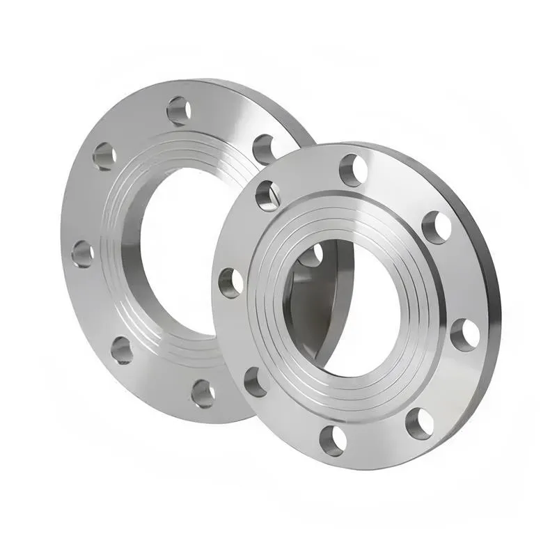
A flange—also referred to as a flange plate or rim—is a component used to connect shafts to one another, or, more commonly, to join the ends of pipes. Flanges are also utilized at the inlet and outlet ports of equipment to facilitate connections between two devices—for instance, the flange on a speed reducer. A "flange connection" or "flanged joint" refers to a detachable joint assembly comprising three interconnected elements—a flange, a gasket, and bolts—that together form a sealed structural unit. In the context of piping systems, a "pipe flange" specifically denotes a flange used for plumbing within the installation; when applied to equipment, it refers to the inlet or outlet flange of that specific device. Flanges feature a series of holes through which bolts are inserted to securely fasten the two flanges together, while a gasket placed between the flanges ensures a leak-proof seal. Flanges are broadly categorized into three types: threaded (screw-in) flanges, welded flanges, and clamp-type flanges. Flanges are invariably used in pairs; threaded flanges are suitable for low-pressure piping applications, whereas welded flanges are required for systems operating at pressures exceeding 4 kilograms per square centimeter. A sealing gasket is inserted between the two flange plates, which are then firmly secured using bolts. The thickness of a flange—as well as the specifications of the bolts used to fasten it—vary depending on the specific pressure rating required for the application. When connecting equipment such as water pumps or valves to piping systems, the corresponding connection points on these devices are often manufactured in the shape of a matching flange; this method of attachment is also referred to as a "flange connection." Generally, any connecting component that utilizes bolts to join and seal the perimeters of two flat surfaces—such as the joints in ventilation ducts—is termed a "flange"; such components may collectively be classified as "flange-type parts." However, since such a connection often constitutes merely a *portion* of a larger device—for instance, the interface between a flange and a water pump—it would be inappropriate to classify the entire water pump itself as a "flange-type part." Conversely, smaller components—such as valves—that feature such flanged interfaces may indeed be appropriately categorized as "flange-type parts."
-:-
For detailed product information, please contact sales.
-:
AISI Type D3 Tool Steel Flange, oil-quenched from 980°C (1800°F), tempered at 450°C Product Information
-:-
For detailed product information, please contact sales.
-:
AISI Type D3 Tool Steel Flange, oil-quenched from 980°C (1800°F), tempered at 450°C Synonyms
-:-
For detailed product information, please contact sales.
-:
AISI Type D3 Tool Steel, oil-quenched from 980°C (1800°F), tempered at 450°C Product Information
-:-
For detailed product information, please contact sales.
-:
# Technical Datasheet: AISI D3 Tool Steel
## Heat Treatment Specification: 980°C (1800°F) Oil Quench & 450°C (842°F) Temper
---
### **1. Product Overview**
**AISI D3** is a **high-carbon, high-chromium, oil-hardening cold work tool steel** renowned for its exceptional wear resistance derived from its high volume of primary chromium carbides. When heat treated through the specific regimen of **austenitizing at 980°C, oil quenching, and tempering at 450°C**, it achieves a highly specialized performance profile. This treatment leverages the **secondary hardening potential** of D3, resulting in a unique combination of **very high toughness, excellent dimensional stability, and retained good wear resistance**, albeit at a lower hardness than typical D3 applications.
This condition represents a **toughness-optimized** variant of D3, designed for applications where resistance to chipping, cracking, and mechanical shock is paramount, and where moderate wear resistance is sufficient. It transforms D3 from a pure wear-resistant steel into a more robust engineering material for demanding forming operations.
---
### **2. Key International Standards & Designations**
| Country/System | Standard Designation | Equivalent Grade Name |
| :--- | :--- | :--- |
| **USA (AISI/SAE)** | **Type D3** | UNS T30403 |
| **USA (ASTM)** | **ASTM A681-08** | Standard Specification for Tool Steels Alloy |
| **ISO** | **ISO 4957:2018** | **1.2080** / X210Cr12 |
| **Europe (EN)** | **EN ISO 4957:2018** | **1.2080** / X210Cr12 |
| **Germany (DIN/W-Nr.)** | **1.2080** | X210Cr12 |
| **Japan (JIS)** | **JIS G4404:2006** | **SKD1** |
| **United Kingdom (BS)** | **BD3** | - |
| **China (GB)** | **GB/T 1299-2014** | **Cr12** |
---
### **3. Chemical Composition (Typical %)**
| Element | Weight % (Typical) | Metallurgical Function |
| :--- | :--- | :--- |
| **Carbon (C)** | 2.05 - 2.20 | Provides carbon for extensive carbide formation and matrix hardening. High carbon is key to secondary hardening reactions during 450°C temper. |
| **Chromium (Cr)** | 11.00 - 12.00 | Forms the primary wear-resistant M₇C₃ carbides and provides moderate corrosion resistance. |
| **Manganese (Mn)** | 0.30 - 0.50 | Enhances hardenability. |
| **Silicon (Si)** | 0.10 - 0.40 | Deoxidizer, provides solid solution strengthening, increases tempering resistance. |
| **Vanadium (V)** | ≤ 0.30 (optional) | Trace addition for grain refinement; contributes to secondary hardening. |
| **Molybdenum (Mo)** | ≤ 0.30 (optional) | Minor addition to improve hardenability and toughness; strong contributor to secondary hardening. |
| **Phosphorus (P)** | ≤ 0.025 | Impurity (controlled). |
| **Sulfur (S)** | ≤ 0.025 | Impurity (controlled). |
**Key Metallurgical Feature:** Tempering at **450°C** places D3 within its **secondary hardening range**. Fine, coherent alloy carbides (rich in Mo and V) precipitate within the martensitic matrix. This **increases hardness slightly from the tempering valley** and, more importantly, **significantly increases toughness, yield strength, and thermal stability** compared to lower tempering temperatures.
---
### **4. Physical & Mechanical Properties (After 980°C Oil Quench + 450°C Double Temper)**
#### **4.1 Standard Heat Treatment Cycle**
* **Preheating:** **Critical (Double Preheat Recommended):** 650°C (1200°F) and 850°C (1560°F) to minimize thermal shock.
* **Austenitizing:** **980°C (1800°F)** – Soak: 20-30 min/inch. Lower temperature helps control retained austenite and grain size, beneficial for toughness.
* **Quenching:** **Moderate- to fast-speed oil** with good agitation to ~50°C.
* **Tempering:** **Double temper at 450°C (842°F)** for minimum 2 hours each. **Cool to room temperature between tempers.** A third temper is advised for critical tools to ensure complete transformation.
* **Expected As-Quenched Hardness:** ~64-66 HRC.
* **Expected Final Hardness:** **54-56 HRC** (Note: Hardness may exhibit a slight increase, or "plateau," from the secondary hardening effect compared to tempering at 350-400°C).
#### **4.2 Final Mechanical Properties (Typical)**
| Property | Value / Rating | Notes |
| :--- | :--- | :--- |
| **Hardness** | **54 - 56 HRC** | The defining characteristic of this condition – lower hardness for vastly improved toughness. |
| **Compressive Strength** | ~ 2300 - 2500 MPa | Remains high, suitable for heavy forming. |
| **Ultimate Tensile Strength** | ~ 1600 - 1800 MPa | |
| **Yield Strength (0.2% Offset)** | ~ 1450 - 1650 MPa | **Relatively high for this hardness**, a benefit of secondary hardening. |
| **Modulus of Elasticity** | ~ 205 - 210 GPa | |
| **Impact Toughness (Charpy)** | **Good (35-55 J)** | **Exceptional for D3.** Can be 4-8 times higher than the 200°C temper condition. The primary reason for selecting this treatment. |
| **Wear Resistance** | **Good** | Still superior to many lower-alloy steels due to primary carbides, but significantly lower than higher-hardness D3 states. |
| **Dimensional Stability** | **Exceptional** | High-temperature tempering relieves nearly all quenching stresses. Retained austenite is fully transformed. |
| **Resistance to Softening** | **Very Good** | The secondary hardened structure is stable up to its tempering temperature (~450°C). |
#### **4.3 Physical Properties (Approx.)**
* Density: 7.70 g/cm³
* Thermal Conductivity: Low (~21 W/m·K)
* Thermal Expansion Coefficient: 10.8 x 10⁻⁶/K (20-400°C)
* Electrical Resistivity: 0.54 µΩ·m
---
### **5. Typical Product Applications**
This high-toughness D3 condition is selected for **demanding, shock-prone applications** where pure wear resistance is secondary to **tool integrity and prevention of catastrophic failure**.
* **Heavy-Duty Forming and Coining Dies:** For thick or high-strength materials where pressure is extreme and tool deflection/stress is high.
* **Large, Complex Blanking and Punching Dies:** For materials that cause high shock loads or where die sections are slender and prone to breakage.
* **Cold Forging Punches and Extrusion Tools:** Subjected to high multi-axial stresses.
* **Shear Blades for Thick Plate:** Where impact loading and uneven wear are factors.
* **Thread Rolling Dies for Large Diameters or Hard Materials:** Requiring high pressure resistance without chipping.
* **Mandrels, Arbors, and Precision Gauges:** Where dimensional stability under load is critical and wear is moderate.
* **Wear Parts in Heavy Machinery:** Subject to combined impact and abrasion.
---
### **6. Processing & Machining Guidelines**
* **Annealed Condition:** ~210-240 HB.
* **Machinability:** **Very Poor.** As with all D3 conditions. Use premium carbide tooling.
* **Grindability:** **Fair to Good (for D3).** The lower final hardness makes grinding easier and less prone to causing cracks. Use appropriate aluminum oxide wheels.
* **EDM Machining:** Well-suited. The stable, low-stress condition is forgiving. A final low-temperature stress relief (180-200°C) after EDM is still recommended for highest precision.
---
### **7. Comparative Performance & Selection Notes**
* **vs. D3 @ 200°C Temper:** This condition sacrifices ~8-10 HRC points but gains **400-800% improvement in impact toughness**. It changes the fundamental failure mode from brittle fracture to gradual wear.
* **vs. D3 @ 315°C Temper:** Offers a further 50-100% increase in toughness for a loss of ~4 HRC. It is the ultimate toughness-optimized condition for D3.
* **vs. A2 or S7 Tool Steel:** At similar hardness (54-56 HRC), D3 in this condition will still have better wear resistance than A2 due to its carbides. S7 may offer even higher toughness but with lower wear resistance.
* **Why This Specific Heat Treat?** The **450°C temper** is a **strategic choice for maximizing tool reliability and safety** in unpredictable, high-stress, or high-value tooling applications. It is used when **tool breakage cost far outweighs wear life extension.**
---
### **8. Important Design & Handling Notes**
* **Design Freedom:** This condition allows for more aggressive tool designs, smaller fillet radii, and thinner sections than any other D3 temper, though good practice remains essential.
* **Primary Failure Mode:** Shifted from **chipping/cracking** to **gradual wear and plastic deformation**. Monitor tools for rolling over or blunting rather than sudden failure.
* **Application Limit:** Not suitable where extreme abrasive wear is the sole concern. Its advantage is in **combined wear and shock** environments.
---
### **9. Conclusion**
**AISI D3 tool steel, heat treated via oil quenching from 980°C and double tempered at 450°C, represents a highly specialized, performance-engineered variant of this classic steel.** It defies D3's traditional "hard-but-brittle" reputation by delivering a level of toughness comparable to many shock-resistant steels, while still retaining a significant portion of its inherent wear resistance due to its primary carbides. This makes it an **invaluable solution for the most challenging cold work applications involving high stress, shock loading, complex geometries, or expensive workpieces**, where preventing catastrophic tool failure is the overriding priority. For engineers facing these extreme conditions, this heat treatment unlocks a new, more reliable dimension of D3's capabilities.
-:-
For detailed product information, please contact sales.
-:
AISI Type D3 Tool Steel, oil-quenched from 980°C (1800°F), tempered at 450°C Specification
Dimensions
Size:
Diameter 20-1000 mm Length <5213 mm
Size:We can customized as required
Standard:
Per your request or drawing
We can customized as required
Properties(Theoretical)
Chemical Composition
-:-
For detailed product information, please contact sales.
-:
AISI Type D3 Tool Steel, oil-quenched from 980°C (1800°F), tempered at 450°C Properties
-:-
For detailed product information, please contact sales.
-:
Applications of AISI Type D3 Tool Steel Flange, oil-quenched from 980°C (1800°F), tempered at 450°C
-:-
For detailed product information, please contact sales.
-:
Chemical Identifiers AISI Type D3 Tool Steel Flange, oil-quenched from 980°C (1800°F), tempered at 450°C
-:-
For detailed product information, please contact sales.
-:
Packing of AISI Type D3 Tool Steel Flange, oil-quenched from 980°C (1800°F), tempered at 450°C
-:-
For detailed product information, please contact sales.
-:
Standard Packing:
-:-
For detailed product information, please contact sales.
-:
Typical bulk packaging includes palletized plastic 5 gallon/25 kg. pails, fiber and Steel Flange drums to 1 ton super sacks in full container (FCL) or truck load (T/L) quantities. Research and sample quantities and hygroscopic, oxidizing or other air sensitive materials may be packaged under argon or vacuum. Solutions are packaged in polypropylene, plastic or glass jars up to palletized 1684 gallon liquid totes Special package is available on request. E FORUs’ is carefully handled to minimize damage during storage and transportation and to preserve the quality of our products in their original condition