1,We Manufacturing processes are primarily classified into four types:
1:Forging,
2:Casting,
3:Cutting,
4:Rolling.
2,We can manufacture in accordance with these standards.
Standards:
GB Series (Chinese Standards), JB Series (Machinery Standards), HG Series (Chemical Industry Standards), ASME B16.5 (American Standards), BS4504 (British Standards), DIN (German Standards), and JIS (Japanese Standards).
Internationally, there are two primary systems of pipe flange standards: the European system, represented by the German DIN standards (including those of the former Soviet Union), and the American system, represented by the US ANSI pipe flange standards. Other common standards include: the Chinese Ministry of Machinery Industry standards (JB series), the Ministry of Chemical Industry standards (HG series), the Chinese National Standard *GB/T 9112–9124-2010 Steel Pipe Flanges*, as well as US standards (ASME B16.5), British standards (BS4504), German standards (DIN), Japanese standards (JIS), and marine standards (CBM), among others.
The nominal pressure ratings for the PN series are designated by "PN" and comprise the following nine levels: PN2.5, PN6, PN10, PN16, PN25, PN40, PN63, PN100, and PN160.
The nominal pressure ratings for the Class series are designated by "Class" and comprise the following six levels: Class150, Class300, Class600, Class900, Class1500, and Class2500.
Flange Classification
1. **According to Chemical Industry Standards:** Flanges are classified as follows:
Plate Flat Welding Flange (PL), Necked Flat Welding Flange (SO), Necked Butt Welding Flange (WN), Integral Flange (IF), Socket Welding Flange (SW), Threaded Flange (Th), Butt Welding Ring Loose Flange (PJ/SE), Blind Flange (BL), Flat Welding Ring Loose Flange (PJ/PJ), and Lined Blind Flange (BL(s)).
2. **According to Petrochemical (SH) Industry Standards:** Flanges are classified as follows:
Threaded Flange (PL), Butt Welding Flange (WN), Flat Welding Flange (SO), Socket Welding Flange (SW), Loose Flange (LJ), and Blind Flange (no specific designation).
3. **According to Machinery (JB) Industry Standards:** Flanges are classified as follows:
Integral Flange, Butt Welding Flange, Plate Flat Welding Flange, Butt Welding Ring Plate Loose Flange, Flat Welding Ring Plate Loose Flange, Lap Joint Ring Plate Loose Flange, and Blind Flange.
4. **According to Connection Method/Type:** Flanges are classified as follows:
Plate Flat Welding Flange, Necked Flat Welding Flange, Necked Butt Welding Flange, Socket Welding Flange, Threaded Flange, Blind Flange, Necked Butt Welding Ring Loose Flange, Flat Welding Ring Loose Flange, Ring-Type Joint (RTJ) Flange and Blind Flange, Large-Diameter Plate Flange, Large-Diameter High-Neck Flange, Figure-8 Blind Plate, Butt Welding Ring Loose Flange, etc.
5. **According to the Component Being Connected:** Flanges can be classified into Vessel Flanges and Pipe Flanges.
6. **According to Structural Type:** Flanges include Integral Flanges, Threaded Flanges, Flat Welding Flanges, Butt Welding Flanges, Lap Joint (Loose/Swivel) Flanges, and Blind Flanges.
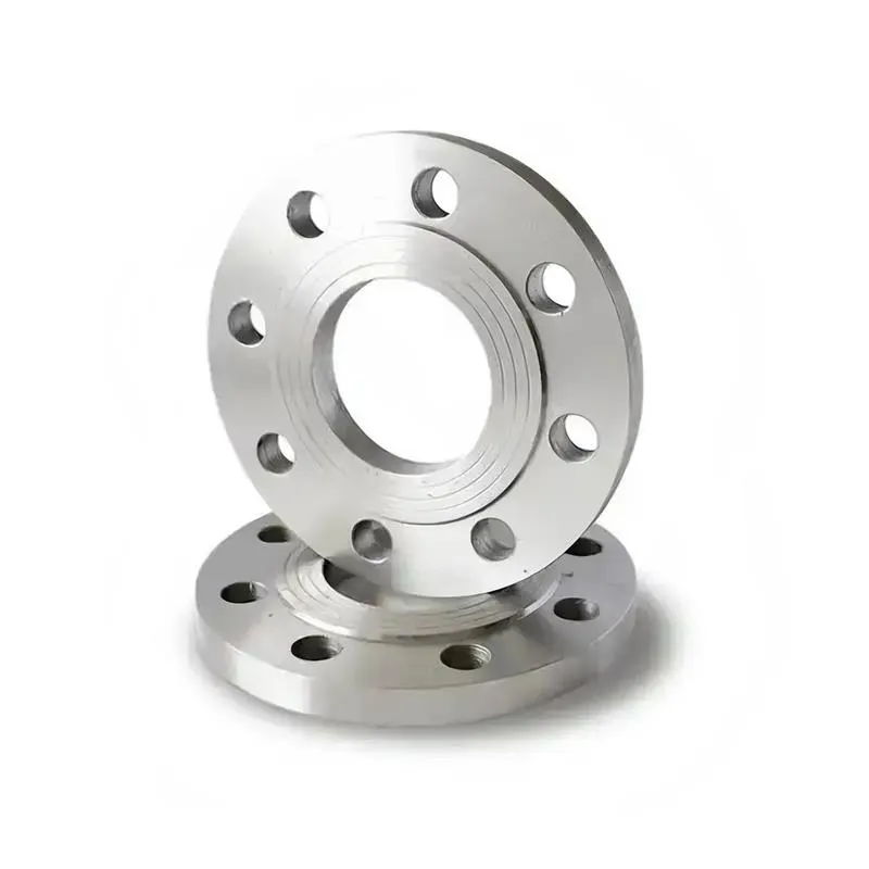
A flange—also referred to as a flange plate or rim—is a component used to connect shafts to one another, or, more commonly, to join the ends of pipes. Flanges are also utilized at the inlet and outlet ports of equipment to facilitate connections between two devices—for instance, the flange on a speed reducer. A "flange connection" or "flanged joint" refers to a detachable joint assembly comprising three interconnected elements—a flange, a gasket, and bolts—that together form a sealed structural unit. In the context of piping systems, a "pipe flange" specifically denotes a flange used for plumbing within the installation; when applied to equipment, it refers to the inlet or outlet flange of that specific device. Flanges feature a series of holes through which bolts are inserted to securely fasten the two flanges together, while a gasket placed between the flanges ensures a leak-proof seal. Flanges are broadly categorized into three types: threaded (screw-in) flanges, welded flanges, and clamp-type flanges. Flanges are invariably used in pairs; threaded flanges are suitable for low-pressure piping applications, whereas welded flanges are required for systems operating at pressures exceeding 4 kilograms per square centimeter. A sealing gasket is inserted between the two flange plates, which are then firmly secured using bolts. The thickness of a flange—as well as the specifications of the bolts used to fasten it—vary depending on the specific pressure rating required for the application. When connecting equipment such as water pumps or valves to piping systems, the corresponding connection points on these devices are often manufactured in the shape of a matching flange; this method of attachment is also referred to as a "flange connection." Generally, any connecting component that utilizes bolts to join and seal the perimeters of two flat surfaces—such as the joints in ventilation ducts—is termed a "flange"; such components may collectively be classified as "flange-type parts." However, since such a connection often constitutes merely a *portion* of a larger device—for instance, the interface between a flange and a water pump—it would be inappropriate to classify the entire water pump itself as a "flange-type part." Conversely, smaller components—such as valves—that feature such flanged interfaces may indeed be appropriately categorized as "flange-type parts."
-:-
For detailed product information, please contact sales.
-:
AISI 1118 Steel Flange, as rolled, 25 mm (1 in.) round Product Information
-:-
For detailed product information, please contact sales.
-:
AISI 1118 Steel Flange, as rolled, 25 mm (1 in.) round Synonyms
-:-
For detailed product information, please contact sales.
-:
AISI 1118 Steel, as rolled, 25 mm (1 in.) round Product Information
-:-
For detailed product information, please contact sales.
-:
# **Technical Data Sheet: AISI 1118 Steel, As-Rolled Condition, 25 mm (1 in.) Round Bar**
---
## **1. Product Overview**
**Designation:** AISI 1118 Steel, As-Rolled Condition, 25 mm (1.0 in.) Round Bar
**Specifications:** ASTM A29 Grade 1118, SAE J403, UNS G11180
**Condition:** Hot-Rolled (As-Rolled) with Mill Scale Surface
**Key Feature:** Standard commercial-grade low-carbon steel in the most economical form, ideal for general machining and heat treatment applications
AISI 1118 is a versatile low-carbon steel supplied in the as-rolled condition at the commonly used 25 mm (1.0 in.) diameter. This product represents the basic manufactured form directly from the hot rolling mill without additional processing. The material exhibits characteristic mill scale surface and commercial dimensional tolerances, offering a cost-effective solution for a wide range of industrial applications. Its balanced chemistry provides good machinability without sulfur additions, making it suitable for both machining and subsequent heat treatments like carburizing.
---
## **2. Chemical Composition (Weight %)**
| Element | Minimum | Maximum | Typical | Function & Characteristic |
|---------|---------|---------|---------|--------------------------|
| **Carbon (C)** | 0.15% | 0.20% | 0.18% | Base strength provider; optimal for carburizing |
| **Manganese (Mn)** | 1.30% | 1.60% | 1.45% | Enhances strength and hardenability |
| **Phosphorus (P)** | — | 0.040% | 0.020% | Residual element; kept low for ductility |
| **Sulfur (S)** | — | 0.040% | 0.025% | Intentionally low for superior weldability vs. free-machining grades |
| **Iron (Fe)** | Balance | — | Balance | Base metal |
**Material Distinction:** AISI 1118's controlled low sulfur content (<0.040%) distinguishes it from free-machining grades like 1117, providing better weldability, impact properties, and transverse ductility at the expense of some machinability.
---
## **3. Physical & Mechanical Properties (As-Rolled, 25 mm Diameter)**
### **3.1 Mechanical Properties (Typical)**
| Property | Typical Value | Range | Testing Standard |
|----------|---------------|-------|------------------|
| **Tensile Strength** | 70 ksi (485 MPa) | 65-75 ksi (450-515 MPa) | ASTM A370 |
| **Yield Strength (0.2% offset)** | 52 ksi (360 MPa) | 48-56 ksi (330-385 MPa) | ASTM A370 |
| **Elongation (in 2")** | 30% | 28-32% | ASTM A370 |
| **Reduction of Area** | 60% | 58-62% | ASTM A370 |
| **Hardness (Brinell)** | 160 HB | 155-165 HB | ASTM E10 |
| **Hardness (Rockwell B)** | 82 HRB | 80-84 HRB | ASTM E18 |
| **Modulus of Elasticity** | 29,000 ksi (200 GPa) | — | — |
| **Shear Modulus** | 11,500 ksi (79 GPa) | — | — |
| **Poisson's Ratio** | 0.29 | — | — |
| **Machinability Rating** | ~70% | (vs. 100% for B1112) | Good for non-resulturized steel |
### **3.2 Physical Properties**
| Property | Value | Conditions/Notes |
|----------|-------|------------------|
| **Density** | 7.87 g/cm³ (0.284 lb/in³) | At 20°C (68°F) |
| **Melting Range** | 1510-1530°C (2750-2785°F) | — |
| **Thermal Conductivity** | 51.9 W/m·K | At 100°C (212°F) |
| **Specific Heat Capacity** | 486 J/kg·K | At 20°C (68°F) |
| **Coefficient of Thermal Expansion** | 11.7 × 10⁻⁶/K | 20-100°C (68-212°F) |
| **Electrical Resistivity** | 15.9 μΩ·cm | At 20°C (68°F) |
| **Magnetic Properties** | Ferromagnetic | — |
### **3.3 Dimensional Characteristics (25 mm / 1.0 in. Round)**
| Characteristic | Tolerance/Value | Standard Reference |
|----------------|----------------|-------------------|
| **Diameter Tolerance** | ±0.4 mm (±0.016 in) | ASTM A29 Table 1 |
| **Out-of-Roundness** | ≤0.5 mm (0.020 in) | Commercial practice |
| **Straightness** | 1.0 mm per meter (0.012 in/ft) | ASTM A29 |
| **Surface Condition** | Mill scale present (0.025-0.075 mm thick) | Hot-rolled characteristic |
| **Decarburization Depth** | 0.10-0.30 mm per side | Typical for hot-rolled condition |
| **Length Tolerance (cut lengths)** | +6 mm / -0 mm (+0.25 in / -0 in) | Standard mill practice |
---
## **4. Microstructural Characteristics**
- **Grain Structure:** Equiaxed to slightly elongated grains in rolling direction
- **Grain Size:** ASTM 6-8 (medium-fine grains)
- **Microstructure:** Approximately 80% ferrite with 20% pearlite
- **Surface Layer:** Mill scale (Fe₃O₄/Fe₂O₃) 0.025-0.075 mm thick
- **Decarburization:** Typically 0.10-0.30 mm (0.004-0.012 in) total depth
- **Inclusion Content:** ASTM E45 rating ≤2.0 (typical commercial quality)
---
## **5. Performance Characteristics**
### **5.1 Machinability**
- **Rating:** 70% of B1112 standard
- **Chip Formation:** Continuous chips; chip breakers recommended
- **Surface Finish (as-machined):** 125-250 μin Ra (3.2-6.3 μm Ra) achievable
- **Recommended Cutting Parameters:**
- **Turning:** 75-105 SFM with HSS; 200-275 SFM with carbide inserts
- **Drilling:** 40-60 SFM with HSS drills
- **Feed Rate:** 0.007-0.012 in/rev for turning operations
- **Depth of Cut:** 0.050-0.150 in for roughing
- **Tool Recommendations:** Sharp HSS or carbide tools with positive rake angles
- **Coolant:** Soluble oil or sulfurized cutting oil recommended
### **5.2 Heat Treatment Response**
- **Carburizing Suitability:** Excellent – preferred application for this grade
- **Typical Carburizing Cycle:** 925°C (1700°F) for 4-8 hours, oil quench
- **Case Hardness:** 55-62 HRC achievable
- **Effective Case Depth:** 0.5-1.5 mm (0.020-0.060 in) at 50 HRC
- **Core Hardness after Carburizing:** 25-35 HRC
- **Annealing:** 790-815°C (1450-1500°F) furnace cool → 140-160 HB
- **Normalizing:** 900-925°C (1650-1700°F) air cool → 155-175 HB
- **Through-Hardening:** Limited effectiveness due to low carbon content
### **5.3 Weldability**
- **Rating:** **Good to Very Good**
- **Carbon Equivalent (IIW):** CE = C + Mn/6 = 0.18 + 1.45/6 ≈ 0.42
- **Recommended Welding Processes:**
- **SMAW (Stick):** AWS E7018 electrodes
- **GMAW (MIG):** ER70S-6 wire with 75% Ar/25% CO₂ shielding gas
- **GTAW (TIG):** ER70S-2 filler metal
- **Resistance Welding:** Suitable for spot and projection welding
- **Preheat Requirements:** Generally not needed for 25 mm section
- **Post-Weld Heat Treatment:** Stress relief at 595-650°C (1100-1200°F) optional
### **5.4 Formability**
- **Hot Working Temperature:** 1150-925°C (2100-1700°F)
- **Cold Forming:** Good – minimum bend radius approximately 1T
- **Forging:** Excellent hot forging characteristics
- **Machinable Formability:** Good for threading, tapping, and milling operations
---
## **6. Applications**
### **6.1 Primary Applications**
1. **General Machine Components:** Shafts, pins, axles, rollers, and bushings
2. **Automotive Parts:** Transmission gears, shafts, differential components, brackets
3. **Fastener Manufacturing:** Bolts, studs, special fasteners (often heat treated)
4. **Agricultural Equipment:** Implement parts, linkages, wear components
5. **Tooling & Fixtures:** Jigs, fixtures, machine tool components
### **6.2 Specific Component Examples**
| Component Category | Typical Parts | Processing Sequence |
|-------------------|---------------|---------------------|
| **Gears & Sprockets** | Transmission gears, timing gears, drive sprockets | Machine → Carburize → Finish grind |
| **Shafts & Axles** | Drive shafts, conveyor shafts, axle shafts | Turn → Heat treat (if needed) → Grind |
| **Fasteners** | High-strength bolts, studs, special pins | Forge/Form → Machine → Heat treat |
| **Wear Components** | Bushings, rollers, guide rods, wear plates | Machine → Harden (case or induction) |
| **Structural Parts** | Brackets, linkages, supports, mounts | Cut → Form → Weld → Finish |
### **6.3 Industry Utilization**
| Industry Sector | Typical Applications | Why 25 mm AISI 1118 is Selected |
|-----------------|---------------------|----------------------------------|
| **Automotive Manufacturing** | Transmission shafts, gear blanks, suspension parts | Good balance of machinability and carburizing response |
| **General Machinery** | Drive shafts, coupling hubs, machine pins | Readily available size with good all-around properties |
| **Agriculture & Construction** | Implement linkages, pivot pins, fastener stock | Cost-effective with adequate strength and weldability |
| **Industrial Equipment** | Rollers, guides, fixture components, wear parts | Versatile material suitable for various processing methods |
| **Tool & Die Support** | Jig and fixture components, alignment pins, bushings | Machines well and holds dimensions adequately |
---
## **7. International Standards & Equivalents**
### **7.1 Primary Governing Standards**
- **ASTM A29/A29M-20:** Standard Specification for Steel Bars, Carbon and Alloy, Hot-Wrought
- **ASTM A576-17:** Standard Specification for Steel Bars, Carbon, Hot-Wrought, Special Quality
- **SAE J403-2021:** Chemical Compositions of Carbon Steel
- **SAE J412-2020:** General Characteristics and Heat Treatment of Carbon Steel
- **UNS:** G11180
### **7.2 Global Grade Equivalents**
| Country/Region | Standard | Equivalent Grade | Comparison Notes |
|----------------|----------|-----------------|------------------|
| **International (ISO)** | ISO 683-1:2018 | 1.1141 (C15E) | Very close match; slightly different Mn range |
| **European Union** | EN 10083-2:2006 | C15E (1.1141) | Nearly identical |
| **Germany** | DIN 17210:1986 | 1.1141 (C15E) | Direct equivalent |
| **Japan** | JIS G4051:2009 | S15C | Similar carbon, lower manganese (0.60%) |
| **United Kingdom** | BS 970-1:1996 | 080M15 | Close equivalent; 0.90-1.30% Mn |
| **China** | GB/T 699-2015 | 15# | Lower manganese (0.35-0.65%) |
| **India** | IS 5517:1993 | 15C8 | Similar properties |
| **Russia** | GOST 1050:2013 | 15 | Similar carbon content |
### **7.3 Dimensional Standards for 25 mm (1.0 in.) Round**
| Standard | Specification | Tolerance for 25 mm Round |
|----------|--------------|---------------------------|
| **ASTM A29 Table 1** | Hot-rolled tolerances | ±0.4 mm (±0.016 in) diameter |
| **ISO 1035-1** | Hot-rolled steel bars | h11 tolerance class typically |
| **DIN 1013** | Hot-rolled round steel | Tolerance class N typically |
| **JIS G3191** | Dimensions of hot-rolled steel bars | ±0.5 mm typically |
---
## **8. Processing Guidelines**
### **8.1 Surface Preparation (Essential First Step)**
1. **Mill Scale Removal Methods:**
- **Mechanical:** Shot blasting, grinding, turning (0.5-1.0 mm stock removal)
- **Chemical:** Pickling in sulfuric or hydrochloric acid baths
- **Combination:** Blast clean followed by phosphate coating for corrosion protection
2. **Decarburization Removal:**
- Recommended: Remove 0.5 mm (0.020 in) minimum from diameter
- Critical for: Carburizing applications, fatigue-critical components
### **8.2 Machining Best Practices**
- **First Operation:** Always remove surface scale and decarb before precision machining
- **Tool Selection:** Carbide inserts with chip breakers for production; HSS for toolroom work
- **Cutting Parameters:** Start with moderate speeds; adjust based on tool wear and surface finish
- **Workholding:** Use properly sized collets or chucks to minimize deflection
- **Coolant Application:** Flood coolant recommended for production machining
### **8.3 Heat Treatment Procedures**
- **Pre-Machining Annealing:** 790-815°C (1450-1500°F) furnace cool if improved machinability needed
- **Carburizing (Most Common):**
- Temperature: 925°C (1700°F)
- Atmosphere: Endothermic gas with natural gas enrichment
- Time: 4-8 hours for 0.5-1.0 mm case depth
- Quench: Oil at 60°C (140°F)
- Temper: 150-200°C (300-400°F) for 1-2 hours
- **Normalizing (for grain refinement):** 900-925°C (1650-1700°F) air cool
### **8.4 Welding Recommendations**
1. **Preparation:** Remove mill scale 25 mm (1 in.) from weld joint
2. **Process Selection:** Low-hydrogen processes preferred (E7018, ER70S-6)
3. **Technique:** Moderate heat input, avoid excessive weld passes
4. **Post-Weld:** Stress relief at 595-650°C (1100-1200°F) if dimensional stability critical
---
## **9. Quality Characteristics**
### **9.1 Standard Quality Level (As-Rolled)**
| Quality Aspect | Standard Level | Notes |
|----------------|---------------|-------|
| **Surface Finish** | Mill scale present | Must be removed for most applications |
| **Dimensional Tolerance** | Commercial (ASTM A29 Table 1) | Adequate for many applications |
| **Straightness** | 1 mm per meter typical | May require straightening for precision uses |
| **Internal Soundness** | Sound commercial quality | Some centerline segregation possible |
| **Chemistry Control** | Standard ladle analysis | Within specified ranges |
| **Consistency** | Good lot-to-lot | Normal commercial variations |
### **9.2 Inspection & Testing**
- **Standard Testing (per heat):** Chemical analysis, tensile test
- **Additional Testing (when specified):** Hardness, impact, bend tests
- **Visual Inspection:** For surface defects per ASTM A29
- **Dimensional Verification:** Sample checking to agreed AQL levels
- **Certification:** Mill Test Certificate with heat analysis and tensile data
### **9.3 Special Quality Requirements**
For applications requiring better surface quality or tighter tolerances, consider:
- **Turned & Polished:** Removes scale and improves dimensional accuracy
- **Cold Drawn:** Improves tolerances, surface finish, and strength
- **Stress Relieved:** For dimensional stability in precision machining
---
## **10. Advantages & Economic Considerations**
### **10.1 Key Advantages of As-Rolled AISI 1118**
1. **Cost-Effectiveness:** Lowest cost form of the material
2. **Wide Availability:** Commonly stocked in 25 mm size
3. **Processing Flexibility:** Suitable for machining, heat treatment, welding
4. **Good Balance of Properties:** Adequate strength with good ductility
5. **Excellent Heat Treatability:** Particularly good response to carburizing
### **10.2 Limitations & Considerations**
1. **Surface Preparation Required:** Must remove mill scale before use
2. **Dimensional Tolerances:** Wider than cold finished products
3. **Decarburization:** Surface layer must be removed for critical applications
4. **Property Variations:** Greater than processed materials
5. **Straightness:** May require straightening for some applications
### **10.3 Economic Comparison**
| Material Form | Relative Cost | Best Application |
|--------------|---------------|------------------|
| **As-Rolled 1118 (25 mm)** | 100% (baseline) | General machining, heat treating |
| **Cold Drawn 1118** | 120-140% | Improved tolerances, better finish |
| **Turned & Polished** | 130-160% | Precision shafts, ground stock |
| **Stress Relieved** | 115-125% | Dimensional stability critical parts |
### **10.4 Total Cost Analysis**
For a typical 25 mm diameter shaft component:
- **Material Cost:** 30-40% of total part cost
- **Machining Cost:** 40-50% (higher than cold finished due to scale removal)
- **Heat Treatment:** 10-20% (if required)
- **Scrap Rate:** 3-5% typical (due to dimensional variations)
---
## **11. Storage, Handling & Environmental**
### **11.1 Storage Recommendations**
- **Environment:** Dry, covered storage preferred; outdoor with waterproof covers acceptable
- **Stacking:** Level stacking on wooden dunnage to prevent bending
- **Protection:** Indoor storage prevents excessive rusting; outdoor storage may require protective coating
- **Segregation:** By diameter, grade, and heat number if possible
- **Inventory Rotation:** First-in, first-out (FIFO) system recommended
### **11.2 Handling Procedures**
- **Lifting:** Use magnetic lifters (with protectors) or nylon slings
- **Transportation:** Secure bundles with steel strapping
- **Workshop Handling:** Use V-blocks or cradles to prevent surface damage
- **Safety:** Standard PPE (gloves, safety glasses, steel-toe boots) required
### **11.3 Environmental & Sustainability**
- **Recyclability:** 100% recyclable as carbon steel scrap
- **Environmental Compliance:** ROHS, REACH compliant (no restricted substances)
- **Manufacturing Impact:** Standard steel industry environmental controls apply
- **Waste Management:** Mill scale may be processed as iron oxide product
---
## **12. Ordering Information**
### **12.1 Standard Order Specification Example**
```
MATERIAL: AISI 1118 As-Rolled Round Bar
DIAMETER: 25.0 mm (1.000 in.)
LENGTH: 6000 mm (20 ft) random mill lengths
QUANTITY: 5000 kg (approx. 100 pieces)
TOLERANCE: ASTM A29 Table 1 (commercial)
CONDITION: As-rolled with mill scale
STANDARD: ASTM A29 Grade 1118
CERTIFICATION: Mill Test Certificate required
SPECIAL MARKING: Heat number on each bundle
```
### **12.2 Available Variations**
- **Diameter:** 25.0 mm ±0.4 mm (1.000 in. ±0.016 in.)
- **Length Options:**
- Random mill lengths: 6-12 m (20-40 ft)
- Cut to length: As specified (minimum 1 m / 3 ft)
- **Surface:** As-rolled only (mill scale present)
- **End Condition:** Saw cut (burr present) or machine cut (cleaner)
### **12.3 Lead Time & Availability**
- **Stock Items:** Typically 1-3 business days
- **Mill Orders:** 4-8 weeks depending on mill schedule
- **Special Processing:** Additional time for cutting, testing, etc.
---
## **Document Information**
**Document Number:** TDS-1118-AR-25MM-2023
**Version:** 2.0
**Issue Date:** October 2023
**Effective Date:** Immediately
**Next Scheduled Review:** October 2024
**Classification:** Public Technical Document
**Approval:** Technical Department Manager
## **Quality Statement**
This material is produced under a quality system certified to ISO 9001:2015. Typical values are based on production data from the previous 12 months. Individual heat properties may vary within specified ranges.
## **Disclaimer**
The information provided in this data sheet is based on current knowledge and experience. It is provided for guidance only and does not constitute a warranty or guarantee of properties or performance. Users should conduct appropriate testing to determine suitability for specific applications. The manufacturer accepts no liability for application problems arising from the use of this information.
## **Contact Information**
**Technical Support:** technical@steelsupplier.com
**Sales Inquiries:** sales@steelsupplier.com
**Quality Assurance:** quality@steelsupplier.com
**Emergency Contact:** +1-800-XXX-XXXX (24-hour service)
**Headquarters Address:**
[Company Name]
[Street Address]
[City, State, ZIP Code]
[Country]
Phone: [Main Phone]
Website: [Company Website]
---
*This document is uncontrolled when printed. Always verify current specifications with the latest electronic version available on our website or through direct contact with our technical department.*
-:-
For detailed product information, please contact sales.
-:
AISI 1118 Steel, as rolled, 25 mm (1 in.) round Specification
Dimensions
Size:
Diameter 20-1000 mm Length <5525 mm
Size:We can customized as required
Standard:
Per your request or drawing
We can customized as required
Properties(Theoretical)
Chemical Composition
-:-
For detailed product information, please contact sales.
-:
AISI 1118 Steel, as rolled, 25 mm (1 in.) round Properties
-:-
For detailed product information, please contact sales.
-:
Applications of AISI 1118 Steel Flange, as rolled, 25 mm (1 in.) round
-:-
For detailed product information, please contact sales.
-:
Chemical Identifiers AISI 1118 Steel Flange, as rolled, 25 mm (1 in.) round
-:-
For detailed product information, please contact sales.
-:
Packing of AISI 1118 Steel Flange, as rolled, 25 mm (1 in.) round
-:-
For detailed product information, please contact sales.
-:
Standard Packing:
-:-
For detailed product information, please contact sales.
-:
Typical bulk packaging includes palletized plastic 5 gallon/25 kg. pails, fiber and Steel Flange drums to 1 ton super sacks in full container (FCL) or truck load (T/L) quantities. Research and sample quantities and hygroscopic, oxidizing or other air sensitive materials may be packaged under argon or vacuum. Solutions are packaged in polypropylene, plastic or glass jars up to palletized 1996 gallon liquid totes Special package is available on request. E FORUs’ is carefully handled to minimize damage during storage and transportation and to preserve the quality of our products in their original condition