1,We Manufacturing processes are primarily classified into four types:
1:Forging,
2:Casting,
3:Cutting,
4:Rolling.
2,We can manufacture in accordance with these standards.
Standards:
GB Series (Chinese Standards), JB Series (Machinery Standards), HG Series (Chemical Industry Standards), ASME B16.5 (American Standards), BS4504 (British Standards), DIN (German Standards), and JIS (Japanese Standards).
Internationally, there are two primary systems of pipe flange standards: the European system, represented by the German DIN standards (including those of the former Soviet Union), and the American system, represented by the US ANSI pipe flange standards. Other common standards include: the Chinese Ministry of Machinery Industry standards (JB series), the Ministry of Chemical Industry standards (HG series), the Chinese National Standard *GB/T 9112–9124-2010 Steel Pipe Flanges*, as well as US standards (ASME B16.5), British standards (BS4504), German standards (DIN), Japanese standards (JIS), and marine standards (CBM), among others.
The nominal pressure ratings for the PN series are designated by "PN" and comprise the following nine levels: PN2.5, PN6, PN10, PN16, PN25, PN40, PN63, PN100, and PN160.
The nominal pressure ratings for the Class series are designated by "Class" and comprise the following six levels: Class150, Class300, Class600, Class900, Class1500, and Class2500.
Flange Classification
1. **According to Chemical Industry Standards:** Flanges are classified as follows:
Plate Flat Welding Flange (PL), Necked Flat Welding Flange (SO), Necked Butt Welding Flange (WN), Integral Flange (IF), Socket Welding Flange (SW), Threaded Flange (Th), Butt Welding Ring Loose Flange (PJ/SE), Blind Flange (BL), Flat Welding Ring Loose Flange (PJ/PJ), and Lined Blind Flange (BL(s)).
2. **According to Petrochemical (SH) Industry Standards:** Flanges are classified as follows:
Threaded Flange (PL), Butt Welding Flange (WN), Flat Welding Flange (SO), Socket Welding Flange (SW), Loose Flange (LJ), and Blind Flange (no specific designation).
3. **According to Machinery (JB) Industry Standards:** Flanges are classified as follows:
Integral Flange, Butt Welding Flange, Plate Flat Welding Flange, Butt Welding Ring Plate Loose Flange, Flat Welding Ring Plate Loose Flange, Lap Joint Ring Plate Loose Flange, and Blind Flange.
4. **According to Connection Method/Type:** Flanges are classified as follows:
Plate Flat Welding Flange, Necked Flat Welding Flange, Necked Butt Welding Flange, Socket Welding Flange, Threaded Flange, Blind Flange, Necked Butt Welding Ring Loose Flange, Flat Welding Ring Loose Flange, Ring-Type Joint (RTJ) Flange and Blind Flange, Large-Diameter Plate Flange, Large-Diameter High-Neck Flange, Figure-8 Blind Plate, Butt Welding Ring Loose Flange, etc.
5. **According to the Component Being Connected:** Flanges can be classified into Vessel Flanges and Pipe Flanges.
6. **According to Structural Type:** Flanges include Integral Flanges, Threaded Flanges, Flat Welding Flanges, Butt Welding Flanges, Lap Joint (Loose/Swivel) Flanges, and Blind Flanges.
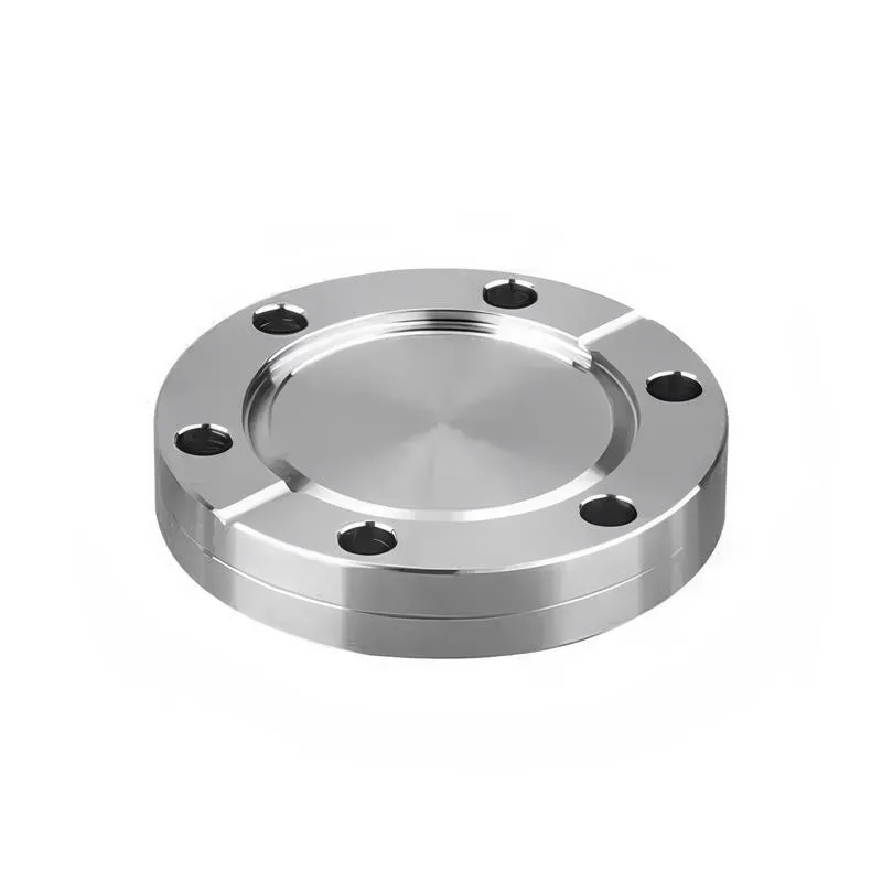
A flange—also referred to as a flange plate or rim—is a component used to connect shafts to one another, or, more commonly, to join the ends of pipes. Flanges are also utilized at the inlet and outlet ports of equipment to facilitate connections between two devices—for instance, the flange on a speed reducer. A "flange connection" or "flanged joint" refers to a detachable joint assembly comprising three interconnected elements—a flange, a gasket, and bolts—that together form a sealed structural unit. In the context of piping systems, a "pipe flange" specifically denotes a flange used for plumbing within the installation; when applied to equipment, it refers to the inlet or outlet flange of that specific device. Flanges feature a series of holes through which bolts are inserted to securely fasten the two flanges together, while a gasket placed between the flanges ensures a leak-proof seal. Flanges are broadly categorized into three types: threaded (screw-in) flanges, welded flanges, and clamp-type flanges. Flanges are invariably used in pairs; threaded flanges are suitable for low-pressure piping applications, whereas welded flanges are required for systems operating at pressures exceeding 4 kilograms per square centimeter. A sealing gasket is inserted between the two flange plates, which are then firmly secured using bolts. The thickness of a flange—as well as the specifications of the bolts used to fasten it—vary depending on the specific pressure rating required for the application. When connecting equipment such as water pumps or valves to piping systems, the corresponding connection points on these devices are often manufactured in the shape of a matching flange; this method of attachment is also referred to as a "flange connection." Generally, any connecting component that utilizes bolts to join and seal the perimeters of two flat surfaces—such as the joints in ventilation ducts—is termed a "flange"; such components may collectively be classified as "flange-type parts." However, since such a connection often constitutes merely a *portion* of a larger device—for instance, the interface between a flange and a water pump—it would be inappropriate to classify the entire water pump itself as a "flange-type part." Conversely, smaller components—such as valves—that feature such flanged interfaces may indeed be appropriately categorized as "flange-type parts."
-:-
For detailed product information, please contact sales.
-:
AISI 8650 Steel Flange, oil quenched 800°C (1470°F), 540°C (1000°F) temper Product Information
-:-
For detailed product information, please contact sales.
-:
AISI 8650 Steel Flange, oil quenched 800°C (1470°F), 540°C (1000°F) temper Synonyms
-:-
For detailed product information, please contact sales.
-:
AISI 8650 Steel, oil quenched 800°C (1470°F), 540°C (1000°F) temper Product Information
-:-
For detailed product information, please contact sales.
-:
# Technical Data Sheet: AISI 8650 Alloy Steel
## Oil Quenched & Tempered Condition (800°C / 1470°F Austenitizing)
---
### 1. Material Overview
**Designation:** AISI 8650 / UNS G86500
**Heat Treatment:** Oil Quenched from 800°C (1470°F) + Tempered at 540°C (1000°F)
**Material Classification:** Nickel-Chromium-Molybdenum Medium-High Carbon Alloy Steel
**Key Characteristics:** This specific heat treatment represents a carefully controlled processing approach for AISI 8650 steel, utilizing a lower austenitizing temperature (800°C/1470°F) compared to the typical 830-855°C range. This refined heat treatment protocol aims to produce a fine-grained microstructure with optimized mechanical properties, balancing high strength, good toughness, and dimensional stability. The 540°C tempering temperature provides the classic balance between strength and ductility, making this condition suitable for critical components requiring reliable performance under demanding service conditions.
---
### 2. International Standards Compliance
**Primary Specifications:**
- **UNS:** G86500
- **ASTM Standards:**
- **A322:** Standard Specification for Steel Bars, Alloy, Standard Grades
- **A331:** Alloy Steel Bars Subject to Mechanical Property Requirements
- **A519:** Seamless Carbon and Alloy Steel Mechanical Tubing
- **SAE/AISI Standards:**
- **SAE J404:** Chemical Compositions of SAE Alloy Steels
- **SAE J412:** Alloy Steel Bars
- **ISO Standards:**
- **ISO 683-11:** Heat-treatable steels, alloy steels and free-cutting steels
- **European Standards:**
- **EN 10083-3:** Steels for quenching and tempering
- Similar to modified 1.6546 (34CrNiMo6) processing
- **Japanese Standards:**
- **JIS G4105:** Chromium molybdenum steels
- **German Standards:**
- **DIN 17200:** Heat-treatable steels
**Special Note:** This specific heat treatment (800°C austenitizing + 540°C temper) represents a refined processing approach rather than a standardized condition. Properties should be verified for specific applications.
---
### 3. Chemical Composition
**Standard Composition Ranges (Weight %):**
| Element | Standard Range | Typical Value | Significance at 800°C Austenitizing |
|---------|---------------|---------------|-------------------------------------|
| **Carbon (C)** | 0.48 - 0.53% | 0.50% | Highest in 86xx series; provides strength; lower austenitizing temp may affect carbide dissolution |
| **Manganese (Mn)** | 0.75 - 1.00% | 0.85% | Enhances hardenability; complete austenitization at 800°C requires sufficient Mn |
| **Silicon (Si)** | 0.15 - 0.30% | 0.25% | Deoxidizer; raises Ac1 temperature, affecting 800°C processing |
| **Nickel (Ni)** | 0.40 - 0.70% | 0.55% | Lowers Ac3 temperature; improves low-temperature toughness |
| **Chromium (Cr)** | 0.40 - 0.60% | 0.50% | Forms carbides; requires adequate temperature for solution |
| **Molybdenum (Mo)** | 0.15 - 0.25% | 0.20% | Strong carbide former; affects hardenability at lower temperatures |
| **Phosphorus (P)** | ≤ 0.035% | 0.020% | Residual element (minimized) |
| **Sulfur (S)** | ≤ 0.040% | 0.025% | Residual element |
| **Iron (Fe)** | Balance | Balance | Matrix element |
**Critical Considerations for 800°C Austenitizing:**
1. **Carbon Content:** At 0.50% C, Ac3 temperature is approximately 775-785°C; 800°C provides minimal superheat above Ac3
2. **Alloy Solution:** Chromium and molybdenum carbides may not fully dissolve at 800°C
3. **Grain Size:** Lower temperature typically produces finer austenite grain size
4. **Transformation:** May result in incomplete austenitization if composition is at high end of ranges
**Recommended Chemistry for 800°C Processing:**
- Carbon: 0.48-0.51% (lower end preferred)
- Manganese: 0.80-0.95% (ensure adequate hardenability)
- Silicon: 0.20-0.28% (controlled for grain refinement)
- Nickel: 0.45-0.60% (improve low-temperature toughness)
- Actual composition should be verified for specific heat treatment response
---
### 4. Heat Treatment Process Details
**Austenitizing at 800°C (1470°F):**
- **Temperature:** 800°C ± 10°C (1470°F ± 18°F)
- **Soaking Time:** 45-60 minutes per inch of thickness (longer than typical due to lower temperature)
- **Atmosphere:** Controlled protective atmosphere essential to prevent decarburization
- **Heating Rate:** Controlled to ensure uniform temperature distribution
- **Special Consideration:** Temperature monitoring critical due to narrow margin above Ac3
**Quenching Process:**
- **Medium:** Fast quenching oil (ISO VG 46-68)
- **Oil Temperature:** 40-60°C (104-140°F) preferred
- **Agitation:** Moderate to vigorous agitation recommended
- **Cooling Rate:** Approximately 50-80°C/second through transformation range
- **Quench Severity (H-value):** Target 0.35-0.45
**Tempering at 540°C (1000°F):**
- **Temperature:** 540°C ± 10°C (1000°F ± 18°F)
- **Time:** 1.5-2.5 hours per inch of thickness
- **Cooling:** Air cool to room temperature
- **Optional:** Double tempering for maximum toughness
**Microstructural Characteristics:**
- **Prior Austenite Grain Size:** ASTM 8-10 (finer than higher temperature austenitizing)
- **As-Quenched Structure:** Predominantly martensite with possible small amounts of bainite
- **Carbide Distribution:** Fine, partially dissolved alloy carbides
- **Retained Austenite:** Typically <3% due to lower Ms temperature
- **Tempered Structure:** Fine tempered martensite with fine carbide precipitation
**Transformation Temperatures (Estimated):**
- **Ac1:** ~725°C (1337°F)
- **Ac3:** ~785°C (1445°F) - critical for 800°C processing
- **Ms:** ~290°C (554°F) - lower due to incomplete carbide solution
- **Mf:** ~150°C (302°F)
---
### 5. Mechanical Properties
**Typical Properties for 25 mm (1") Diameter:**
| Property | Typical Value Range | Test Standard | Notes |
|----------|---------------------|---------------|-------|
| **Tensile Strength** | 1100-1240 MPa | ASTM A370 | 160-180 ksi |
| **Yield Strength (0.2%)** | 965-1100 MPa | ASTM A370 | 140-160 ksi |
| **Elongation (in 50 mm)** | 12-16% | ASTM A370 | Good for this strength level |
| **Reduction of Area** | 40-50% | ASTM A370 | Energy absorption capability |
| **Hardness** | 34-40 HRC | ASTM E18 | 321-375 HB |
| **Charpy V-Notch (20°C)** | 25-40 J | ASTM E23 | 18-30 ft-lb |
| **Charpy V-Notch (-18°C)** | 15-25 J | ASTM E23 | 11-18 ft-lb |
| **Fatigue Strength (10⁷ cycles)** | 500-600 MPa | ASTM E466 | 73-87 ksi |
| **Fracture Toughness (K₁C)** | 50-70 MPa√m | ASTM E399 | 46-64 ksi√in |
| **Modulus of Elasticity** | 205 GPa | ASTM E111 | 29.7 × 10⁶ psi |
**Property Variation by Section Size:**
| Diameter | Surface Hardness | Core Hardness | Tensile Strength | Impact Toughness |
|----------|-----------------|---------------|-----------------|------------------|
| **25 mm (1")** | 35-40 HRC | 34-39 HRC | 1100-1240 MPa | 25-40 J |
| **50 mm (2")** | 33-38 HRC | 32-37 HRC | 1035-1170 MPa | 23-38 J |
| **75 mm (3")** | 31-36 HRC | 30-35 HRC | 965-1100 MPa | 21-36 J |
| **100 mm (4")** | 29-34 HRC | 28-33 HRC | 895-1035 MPa | 19-34 J |
**Comparison with Standard 845°C Austenitizing:**
- **Strength:** Similar or slightly lower due to incomplete carbide solution
- **Toughness:** Potentially better due to finer grain size
- **Hardness:** Similar when properly processed
- **Dimensional Stability:** Better due to lower processing temperature
**Physical Properties:**
| Property | Value | Units | Conditions |
|----------|-------|-------|------------|
| **Density** | 7.85 | g/cm³ | At 20°C |
| **Thermal Conductivity** | 41.0 | W/m·K | At 100°C |
| **Specific Heat Capacity** | 460 | J/kg·K | At 100°C |
| **Coefficient of Thermal Expansion** | 11.5 × 10⁻⁶ | /°C | 20-100°C range |
| **Electrical Resistivity** | 0.24 | μΩ·m | At 20°C |
---
### 6. Material Characteristics & Performance
**Advantages of 800°C Austenitizing:**
1. **Fine Grain Structure:** Produces ASTM 8-10 grain size for improved toughness
2. **Reduced Distortion:** Lower processing temperature minimizes thermal stresses
3. **Improved Dimensional Stability:** Less growth and distortion during heat treatment
4. **Energy Efficiency:** Lower temperature reduces energy consumption
5. **Potential for Better Toughness:** Finer microstructure may enhance impact resistance
6. **Reduced Scaling:** Lower temperature minimizes surface oxidation
**Considerations & Limitations:**
1. **Critical Temperature Control:** Narrow margin above Ac3 requires precise temperature control
2. **Incomplete Austenitization Risk:** Possible if composition or temperature varies
3. **Reduced Hardenability:** Lower temperature may affect through-hardening capability
4. **Longer Soak Times Required:** To ensure complete transformation
5. **Property Consistency:** More sensitive to processing variations
**Performance Characteristics:**
- **Wear Resistance:** Good due to high carbon content and hardness
- **Fatigue Performance:** Excellent for high-cycle applications
- **Notch Sensitivity:** Moderate; proper design important
- **Temperature Stability:** Suitable for service up to 300°C (570°F)
- **Corrosion Resistance:** Similar to other alloy steels; requires protection
**Special Processing Recommendations:**
1. **Preheating:** Recommended at 650°C (1200°F) before austenitizing
2. **Temperature Uniformity:** ±5°C control recommended in furnace
3. **Quenching Delay:** Minimize to prevent ferrite formation
4. **Immediate Tempering:** Essential to prevent cracking
5. **Process Verification:** Regular testing recommended
---
### 7. Applications
**Components Benefiting from Fine Grain Structure:**
**Precision Machinery Components:**
- High-precision gears and shafts
- Machine tool spindles and arbors
- Precision bearing races
- Measurement instrument components
- Optical equipment parts
**Automotive & Transportation:**
- High-performance transmission gears
- Precision steering components
- Engine timing gears
- High-wear suspension components
- Critical fasteners and bolts
**Aerospace Components:**
- Non-critical structural components
- Actuator mechanisms
- Landing gear secondary components
- Control system components
- Special fasteners
**Oil & Gas Industry:**
- Precision valve components
- Metering equipment parts
- Small pump shafts
- Instrumentation components
- Special tooling
**Industrial Equipment:**
- Precision rollers and guides
- Wear plates and inserts
- Special tool holders
- Measuring equipment components
- High-wear machine parts
**Defense Applications:**
- Firearm components
- Optical mounting systems
- Precision mechanism parts
- Wear-resistant components
- Special fastening systems
**Applications Where This Treatment is Particularly Suitable:**
- Components requiring minimal distortion
- Parts with tight dimensional tolerances
- Applications benefiting from fine grain structure
- Components where toughness is critical
- Parts requiring good fatigue resistance
**Typical Service Conditions:**
- Static loads: Up to 70% of yield strength
- Dynamic loads: With proper design factors
- Temperature range: -40°C to +300°C (-40°F to +570°F)
- Wear conditions: With proper lubrication
- Corrosive environments: With appropriate protection
---
### 8. Machining & Processing
**Machining in Heat-Treated Condition:**
- **Machinability Rating:** 45-50% (compared to 100% for B1112)
- **Recommended Tools:** Carbide or ceramic inserts
- **Cutting Parameters:**
- Turning: 60-90 m/min (200-300 SFM) with carbide
- Milling: 50-80 m/min (165-260 SFM)
- Drilling: 20-30 m/min (65-100 SFM) with carbide drills
- **Feed Rates:** 0.10-0.25 mm/rev (0.004-0.010 ipr)
- **Depth of Cut:** Up to 3 mm (0.120") depending on setup
- **Coolant:** Essential for tool life and dimensional control
- **Chip Formation:** Continuous chips; chip breakers essential
**Alternative Machining Strategy:**
1. Rough machine in annealed condition
2. Heat treat (800°C Q + 540°C T)
3. Finish machine with carbide tools
4. Final grinding if required for precision
**Grinding Recommendations:**
- **Wheel Selection:** Aluminum oxide or CBN
- **Parameters:** Light passes to minimize heat generation
- **Coolant:** Ample supply to prevent thermal damage
- **Dressing:** Regular to maintain wheel condition
**Heat Treatment Best Practices:**
- **Process Control:** Statistical process control recommended
- **Temperature Verification:** Regular calibration of equipment
- **Quench Agitation:** Controlled for consistency
- **Tempering:** Sufficient time for complete transformation
- **Documentation:** Complete records for traceability
---
### 9. Quality Assurance & Testing
**Critical Testing Requirements:**
1. **Microstructural Examination:**
- Grain size verification (ASTM E112)
- Microstructure evaluation
- Inclusion rating (ASTM E45)
2. **Hardness Testing:**
- Multiple locations including surface and core
- Statistical analysis of results
3. **Mechanical Testing:**
- Tensile testing from representative locations
- Impact testing at specified temperatures
4. **Non-Destructive Testing:**
- As specified for critical applications
**Acceptance Criteria for This Specific Treatment:**
- **Hardness:** Within specified range for section size
- **Grain Size:** ASTM 8 minimum
- **Microstructure:** Predominantly tempered martensite
- **Decarburization:** ≤0.20 mm maximum
- **Surface Condition:** Free of cracks and excessive scale
**Certification Requirements:**
- Mill Test Certificate EN 10204 3.1 or 3.2
- Complete heat treatment records
- Mechanical test reports
- Microstructural examination report
- Traceability documentation
**Process Verification Testing:**
- Regular production testing
- Statistical analysis of results
- Correlation with processing parameters
- Continuous improvement initiatives
---
### 10. Technical Recommendations
**Design Guidelines:**
- **Allowable Stresses:** Based on verified mechanical properties
- **Safety Factors:**
- Static loading: 2.0-2.5
- Fatigue loading: 1.8-2.2
- Impact loading: 2.5-3.5
- **Notch Sensitivity:** Consider in design with stress concentrations
- **Surface Treatments:** Shot peening beneficial for fatigue
**Manufacturing Considerations:**
- **Dimensional Allowances:** Account for heat treatment effects
- **Surface Finish:** Specify based on application requirements
- **Quality Control:** Implement throughout manufacturing process
- **Documentation:** Maintain complete records
**Procurement Specification Example:**
```plaintext
MATERIAL: AISI 8650 Alloy Steel
HEAT TREATMENT: Oil quenched from 800°C ±10°C, tempered at 540°C ±10°C
PROPERTIES: For 25 mm diameter:
- Tensile: 1100-1240 MPa minimum
- Yield: 965-1100 MPa minimum
- Hardness: 34-40 HRC
- Impact: 25 J minimum at 20°C
MICROSTRUCTURE: Grain size ASTM 8 minimum, tempered martensite
CERTIFICATION: EN 10204 3.2 with full traceability
TESTING: Mechanical and microstructural testing required
```
**Special Processing Notes:**
- This specific heat treatment requires precise temperature control
- Regular verification of properties recommended
- Consider statistical process control for consistency
- Work with experienced heat treaters familiar with this approach
---
### 11. Comparative Analysis
**vs. Standard 845°C Austenitizing (Same Temper):**
- **Strength:** 5-10% lower potentially
- **Toughness:** 10-20% better potentially
- **Distortion:** 20-30% less typically
- **Grain Size:** Finer (ASTM 8-10 vs 6-8)
- **Processing Control:** More critical
**vs. Other Heat Treatments of AISI 8650:**
- **800°C Q + 540°C T:** Balanced properties, fine grain
- **845°C Q + 540°C T:** Higher strength potential
- **800°C Q + 595°C T:** Better toughness, lower strength
- **845°C Q + 425°C T:** Higher hardness, lower toughness
**Selection Guidelines:**
- **Choose 800°C treatment when:**
- Fine grain structure is important
- Dimensional stability is critical
- Toughness is a priority
- Components have complex geometries
- **Consider standard 845°C when:**
- Maximum strength is required
- Through-hardening of larger sections needed
- Standardized processing preferred
---
**Disclaimer:** This technical data sheet describes AISI 8650 steel with a specific heat treatment of oil quenching from 800°C followed by tempering at 540°C. This represents a refined processing approach that requires precise control and verification. Properties may vary based on specific composition, section size, and processing details. For critical applications, conduct appropriate testing and consult with materials engineering professionals.
---
**Document Control**
- **Document:** TDS-8650-800Q-540T
- **Revision:** 1.0
- **Date:** March 2024
- **Prepared By:** Materials Engineering Department
- **Approved By:** Technical Manager
- **Quality System:** ISO 9001:2015 Certified
- **Special Note:** This specific heat treatment requires precise process control
-:-
For detailed product information, please contact sales.
-:
AISI 8650 Steel, oil quenched 800°C (1470°F), 540°C (1000°F) temper Specification
Dimensions
Size:
Diameter 20-1000 mm Length <6366 mm
Size:We can customized as required
Standard:
Per your request or drawing
We can customized as required
Properties(Theoretical)
Chemical Composition
-:-
For detailed product information, please contact sales.
-:
AISI 8650 Steel, oil quenched 800°C (1470°F), 540°C (1000°F) temper Properties
-:-
For detailed product information, please contact sales.
-:
Applications of AISI 8650 Steel Flange, oil quenched 800°C (1470°F), 540°C (1000°F) temper
-:-
For detailed product information, please contact sales.
-:
Chemical Identifiers AISI 8650 Steel Flange, oil quenched 800°C (1470°F), 540°C (1000°F) temper
-:-
For detailed product information, please contact sales.
-:
Packing of AISI 8650 Steel Flange, oil quenched 800°C (1470°F), 540°C (1000°F) temper
-:-
For detailed product information, please contact sales.
-:
Standard Packing:
-:-
For detailed product information, please contact sales.
-:
Typical bulk packaging includes palletized plastic 5 gallon/25 kg. pails, fiber and Steel Flange drums to 1 ton super sacks in full container (FCL) or truck load (T/L) quantities. Research and sample quantities and hygroscopic, oxidizing or other air sensitive materials may be packaged under argon or vacuum. Solutions are packaged in polypropylene, plastic or glass jars up to palletized 2837 gallon liquid totes Special package is available on request. E FORUs’ is carefully handled to minimize damage during storage and transportation and to preserve the quality of our products in their original condition


 High Speed Steel Flange")

