1,We Manufacturing processes are primarily classified into four types:
1:Forging,
2:Casting,
3:Cutting,
4:Rolling.
2,We can manufacture in accordance with these standards.
Standards:
GB Series (Chinese Standards), JB Series (Machinery Standards), HG Series (Chemical Industry Standards), ASME B16.5 (American Standards), BS4504 (British Standards), DIN (German Standards), and JIS (Japanese Standards).
Internationally, there are two primary systems of pipe flange standards: the European system, represented by the German DIN standards (including those of the former Soviet Union), and the American system, represented by the US ANSI pipe flange standards. Other common standards include: the Chinese Ministry of Machinery Industry standards (JB series), the Ministry of Chemical Industry standards (HG series), the Chinese National Standard *GB/T 9112–9124-2010 Steel Pipe Flanges*, as well as US standards (ASME B16.5), British standards (BS4504), German standards (DIN), Japanese standards (JIS), and marine standards (CBM), among others.
The nominal pressure ratings for the PN series are designated by "PN" and comprise the following nine levels: PN2.5, PN6, PN10, PN16, PN25, PN40, PN63, PN100, and PN160.
The nominal pressure ratings for the Class series are designated by "Class" and comprise the following six levels: Class150, Class300, Class600, Class900, Class1500, and Class2500.
Flange Classification
1. **According to Chemical Industry Standards:** Flanges are classified as follows:
Plate Flat Welding Flange (PL), Necked Flat Welding Flange (SO), Necked Butt Welding Flange (WN), Integral Flange (IF), Socket Welding Flange (SW), Threaded Flange (Th), Butt Welding Ring Loose Flange (PJ/SE), Blind Flange (BL), Flat Welding Ring Loose Flange (PJ/PJ), and Lined Blind Flange (BL(s)).
2. **According to Petrochemical (SH) Industry Standards:** Flanges are classified as follows:
Threaded Flange (PL), Butt Welding Flange (WN), Flat Welding Flange (SO), Socket Welding Flange (SW), Loose Flange (LJ), and Blind Flange (no specific designation).
3. **According to Machinery (JB) Industry Standards:** Flanges are classified as follows:
Integral Flange, Butt Welding Flange, Plate Flat Welding Flange, Butt Welding Ring Plate Loose Flange, Flat Welding Ring Plate Loose Flange, Lap Joint Ring Plate Loose Flange, and Blind Flange.
4. **According to Connection Method/Type:** Flanges are classified as follows:
Plate Flat Welding Flange, Necked Flat Welding Flange, Necked Butt Welding Flange, Socket Welding Flange, Threaded Flange, Blind Flange, Necked Butt Welding Ring Loose Flange, Flat Welding Ring Loose Flange, Ring-Type Joint (RTJ) Flange and Blind Flange, Large-Diameter Plate Flange, Large-Diameter High-Neck Flange, Figure-8 Blind Plate, Butt Welding Ring Loose Flange, etc.
5. **According to the Component Being Connected:** Flanges can be classified into Vessel Flanges and Pipe Flanges.
6. **According to Structural Type:** Flanges include Integral Flanges, Threaded Flanges, Flat Welding Flanges, Butt Welding Flanges, Lap Joint (Loose/Swivel) Flanges, and Blind Flanges.
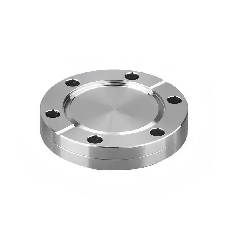
A flange—also referred to as a flange plate or rim—is a component used to connect shafts to one another, or, more commonly, to join the ends of pipes. Flanges are also utilized at the inlet and outlet ports of equipment to facilitate connections between two devices—for instance, the flange on a speed reducer. A "flange connection" or "flanged joint" refers to a detachable joint assembly comprising three interconnected elements—a flange, a gasket, and bolts—that together form a sealed structural unit. In the context of piping systems, a "pipe flange" specifically denotes a flange used for plumbing within the installation; when applied to equipment, it refers to the inlet or outlet flange of that specific device. Flanges feature a series of holes through which bolts are inserted to securely fasten the two flanges together, while a gasket placed between the flanges ensures a leak-proof seal. Flanges are broadly categorized into three types: threaded (screw-in) flanges, welded flanges, and clamp-type flanges. Flanges are invariably used in pairs; threaded flanges are suitable for low-pressure piping applications, whereas welded flanges are required for systems operating at pressures exceeding 4 kilograms per square centimeter. A sealing gasket is inserted between the two flange plates, which are then firmly secured using bolts. The thickness of a flange—as well as the specifications of the bolts used to fasten it—vary depending on the specific pressure rating required for the application. When connecting equipment such as water pumps or valves to piping systems, the corresponding connection points on these devices are often manufactured in the shape of a matching flange; this method of attachment is also referred to as a "flange connection." Generally, any connecting component that utilizes bolts to join and seal the perimeters of two flat surfaces—such as the joints in ventilation ducts—is termed a "flange"; such components may collectively be classified as "flange-type parts." However, since such a connection often constitutes merely a *portion* of a larger device—for instance, the interface between a flange and a water pump—it would be inappropriate to classify the entire water pump itself as a "flange-type part." Conversely, smaller components—such as valves—that feature such flanged interfaces may indeed be appropriately categorized as "flange-type parts."
-:-
For detailed product information, please contact sales.
-:
Latrobe LSS™ S1 Shock-Resisting Tool Steel Flange (ASTM S1) Product Information
-:-
For detailed product information, please contact sales.
-:
Latrobe LSS™ S1 Shock-Resisting Tool Steel Flange (ASTM S1) Synonyms
-:-
For detailed product information, please contact sales.
-:
Latrobe LSS™ S1 Shock-Resisting Tool Steel (ASTM S1) Product Information
-:-
For detailed product information, please contact sales.
-:
# **PRODUCT DATASHEET: LATROBE LSS™ S1 SHOCK-RESISTING TOOL STEEL (ASTM S1)**
## **EXECUTIVE SUMMARY**
Latrobe LSS™ **S1 Shock-Resisting Tool Steel** is a premium **tungsten-chromium-vanadium alloy steel** specifically engineered for **impact applications requiring exceptional toughness combined with good wear resistance**. As a member of the **S-series (shock-resisting) tool steels**, S1 excels in applications subjected to severe shock loading, high stress impacts, and intermittent service conditions. With its unique combination of **high toughness (up to 300 ft-lb Charpy impact), good wear resistance, and moderate hot hardness**, Latrobe S1 represents the industry benchmark for **chisels, punches, shear blades, and other impact tools** where fracture resistance is paramount.
Manufactured using Latrobe's proprietary melting and thermomechanical processing, this grade offers superior **microstructural homogeneity, enhanced carbide distribution, and consistent through-hardening characteristics** compared to conventional S1 steels. The optimized chemistry provides excellent **deep hardenability** while maintaining the shock resistance that defines this class of tool steels.
---
## **METALLURGICAL DESIGN**
### **Material Philosophy**
S1 tool steel employs a specialized **tungsten-chromium-vanadium alloying system** designed to achieve:
1. **Maximum Toughness:** High silicon (1.00-1.50%) and moderate carbon (0.40-0.55%) content create a balanced microstructure that absorbs impact energy without fracturing
2. **Shock Resistance:** Fine, evenly distributed alloy carbides within a tough martensitic matrix resist crack initiation and propagation
3. **Wear Resistance:** Tungsten and chromium carbides provide adequate wear resistance for most impact applications
4. **Hot Hardness:** Retains hardness at moderate operating temperatures (up to 900°F/482°C)
### **Manufacturing Excellence**
- **Controlled Carbide Distribution:** Proprietary processing ensures uniform carbide size and distribution
- **Optimized Grain Structure:** Fine austenitic grain size (ASTM 8-10) for maximum toughness
- **Stress Management:** Careful cooling and tempering minimize residual stresses
- **Consistent Hardenability:** Reliable through-hardening in sections up to 4 inches
---
## **CHEMICAL COMPOSITION**
### **Standard Composition (Weight %)**
| Element | Minimum | Maximum | Typical | Metallurgical Function |
|---------|---------|---------|---------|------------------------|
| **Carbon (C)** | 0.40 | 0.55 | 0.50 | Hardness, wear resistance, strength |
| **Tungsten (W)** | 1.50 | 3.00 | 2.50 | Hot hardness, wear resistance, carbide formation |
| **Chromium (Cr)** | 1.00 | 1.80 | 1.50 | Hardenability, wear resistance, toughness |
| **Vanadium (V)** | 0.15 | 0.30 | 0.25 | Grain refinement, secondary hardening, wear resistance |
| **Silicon (Si)** | 0.90 | 1.50 | 1.20 | Toughness, temper resistance, deoxidation |
| **Manganese (Mn)** | 0.10 | 0.40 | 0.30 | Hardenability, strength |
| **Molybdenum (Mo)** | — | 0.50 | 0.25 | Optional, enhances hardenability and toughness |
| **Nickel (Ni)** | — | 0.30 | 0.15 | Optional, improves toughness |
| **Sulfur (S)** | — | 0.030 | 0.010 | Residual |
| **Phosphorus (P)** | — | 0.030 | 0.015 | Residual |
### **Latrobe Premium Modifications**
- **Enhanced Purity:** Lower sulfur and phosphorus for improved transverse toughness
- **Micro-Alloying:** Controlled boron additions (0.001-0.003%) for optimized hardenability
- **Gas Control:** Oxygen <25 ppm, Hydrogen <2 ppm through advanced melting practices
### **Comparative Chemistry Advantages**
- **Higher Silicon:** Compared to other shock steels (S2, S5, S7) for superior toughness
- **Balanced Tungsten:** Optimized for hot hardness without excessive carbide formation
- **Vanadium Control:** Sufficient for grain refinement without compromising machinability
---
## **PHYSICAL & MECHANICAL PROPERTIES**
### **Hardened and Tempered Condition**
*Typical Heat Treatment: Austenitize 1750°F (954°C), quench, temper at 400-1000°F (204-538°C)*
| Property | 54-56 HRC | 56-58 HRC | 58-60 HRC | Units | Test Standard |
|----------|------------|------------|------------|--------|----------------|
| **Hardness** | 54-56 | 56-58 | 58-60 | HRC | ASTM E18 |
| **Tensile Strength** | 290-310 | 310-330 | 330-350 | ksi | ASTM E8 |
| **Yield Strength (0.2%)** | 260-280 | 280-300 | 300-320 | ksi | ASTM E8 |
| **Elongation** | 10-12 | 8-10 | 6-8 | % | ASTM E8 |
| **Reduction of Area** | 40-45 | 35-40 | 30-35 | % | ASTM E8 |
| **Impact Energy (Charpy V)** | 250-300 | 200-250 | 150-200 | ft-lb | ASTM E23 |
### **Physical Properties**
| Property | Value | Units | Temperature/Condition |
|----------|-------|--------|----------------------|
| **Density** | 0.283 | lb/in³ (7.83 g/cm³) | Room Temperature |
| **Elastic Modulus** | 29.5 × 10⁶ | psi (203 GPa) | Room Temperature |
| **Shear Modulus** | 11.5 × 10⁶ | psi (79 GPa) | Room Temperature |
| **Poisson's Ratio** | 0.29 | | Room Temperature |
| **Thermal Conductivity** | 20.5 | BTU·in/(hr·ft²·°F) | 212°F (100°C) |
| **Specific Heat** | 0.11 | BTU/(lb·°F) | 68-212°F (20-100°C) |
| **Coefficient of Thermal Expansion** | 6.3 × 10⁻⁶ | /°F | 68-600°F (20-315°C) |
| **Electrical Resistivity** | 48 | μΩ·cm | Room Temperature |
| **Magnetic Response** | Ferromagnetic | | All conditions |
### **Hardenability Data (Jominy Test)**
- **Surface Hardness:** 63-65 HRC (as-quenched)
- **Depth for 60 HRC:** 0.5 inch from quenched end
- **Depth for 50 HRC:** 2.0 inches from quenched end
- **Full Hardening Capacity:** Up to 4-inch diameter sections (oil quench)
### **Hot Hardness Properties**
| Temperature | Hardness Retention | Notes |
|-------------|-------------------|-------|
| **Room Temperature** | 100% | Baseline |
| **400°F (204°C)** | 95-98% | Excellent retention |
| **600°F (316°C)** | 90-93% | Good for hot work applications |
| **800°F (427°C)** | 80-85% | Superior to most shock steels |
| **900°F (482°C)** | 70-75% | Maximum recommended service temperature |
### **Machinability Data (Annealed Condition ~200 HB)**
| Operation | Cutting Speed | Feed Rate | Tool Material | Notes |
|-----------|---------------|-----------|---------------|-------|
| **Turning** | 150-200 SFM | 0.010-0.020 IPR | C2/C3 Carbide | Moderate difficulty |
| **Milling** | 100-150 SFM | 0.004-0.008 IPT | HSS or Carbide | Use rigid setups |
| **Drilling** | 60-100 SFM | 0.004-0.008 IPR | HSS Drills | Peck drilling recommended |
| **Sawing** | 80-120 FPM | Moderate feed | Bimetal Blades | Use coolant |
*Machinability Rating: Approximately 40-50% of 1212 steel (annealed condition)*
---
## **INTERNATIONAL STANDARDS & SPECIFICATIONS**
### **Primary Material Standards**
| Standard | Designation | Equivalent Grades | Notes |
|----------|-------------|-------------------|-------|
| **ASTM A681** | S1 Type 1 | Primary specification | |
| **UNS** | T41901 | Unified Numbering System | |
| **AISI/SAE** | S1 | American Iron and Steel Institute | |
| **DIN** | 1.2550 | German Standard | 50WCrV8 |
| **ISO** | 50WCrV8 | International Standard | |
| **JIS** | SKS41 | Japanese Industrial Standard | |
| **GB** | 6W6Mo5Cr4V | Chinese Standard | Similar characteristics |
| **AMS** | 6490 | Aerospace Material Specification | |
### **Industry Specifications**
- **Tool & Die Industry:** Standard shock-resisting tool steel specification
- **Forging Industry:** Common for hot work applications requiring toughness
- **Mining & Construction:** Standard for impact tools and wear parts
### **Quality Standards**
- **ASTM A600:** Standard Specification for Tool Steel High Speed
- **ASTM A681:** Alloy Tool Steels
- **ASTM E45:** Determining Inclusion Content of Steel
- **Internal Latrobe Standards:** Enhanced requirements for premium tool steel
---
## **APPLICATIONS**
### **Primary Impact Applications**
#### **Hand Tools**
- **Chisels:** Cold chisels, masonry chisels, wood chisels
- **Punches:** Center punches, pin punches, drift punches
- **Hammers:** Ball peen hammers, sledge hammer faces
- **Pry Bars:** Various pry and crow bar applications
#### **Industrial Tools**
- **Shear Blades:** For metal, plastic, and composite materials
- **Punch and Die Sets:** For punching operations
- **Hot Work Tools:** Forging dies, heading dies, hot punches
- **Gages:** Thread gages, plug gages, ring gages requiring toughness
#### **Mining & Construction**
- **Rock Drilling Tools:** Drill bits, rock drill rods
- **Excavator Teeth:** Points and adapters
- **Crusher Parts:** Hammers, impact bars, breaker plates
- **Wear Parts:** Bucket teeth, cutting edges
### **Specialized Applications**
#### **Aerospace & Defense**
- **High-Stress Components:** Aircraft landing gear tools, missile components
- **Armor Piercing Tools:** Specialized cutting and breaching tools
- **Maintenance Tools:** High-impact repair and maintenance tools
#### **Oil & Gas**
- **Downhole Tools:** Shock subs, drilling jars
- **Wellhead Components:** High-pressure valve components
- **Fishing Tools:** Overshots, spears, milling tools
#### **Manufacturing**
- **Forging Dies:** For impact forging operations
- **Extrusion Tools:** For high-impact extrusion applications
- **Stamping Dies:** For heavy-gauge materials
### **Service Recommendations**
| Application Type | Recommended Hardness | Tempering Temperature | Expected Service Life |
|-----------------|----------------------|-----------------------|------------------------|
| **Severe Impact** | 54-56 HRC | 800-1000°F (427-538°C) | Moderate |
| **Heavy Impact** | 56-58 HRC | 600-800°F (316-427°C) | Good |
| **Moderate Impact** | 58-60 HRC | 400-600°F (204-316°C) | Excellent |
| **Hot Work** | 52-54 HRC | 900-1050°F (482-566°C) | Moderate |
---
## **HEAT TREATMENT**
### **Annealing**
- **Temperature:** 1450-1500°F (788-816°C)
- **Cooling:** Slow furnace cool at 20-30°F/hour (11-17°C/hour) to 1000°F (538°C)
- **Resultant Hardness:** 192-212 HB (90-95 HRB)
- **Microstructure:** Spheroidized carbides in ferritic matrix
### **Stress Relieving**
- **Temperature:** 1100-1250°F (593-677°C)
- **Time:** 1-2 hours per inch of thickness
- **Cooling:** Air cool
- **Purpose:** Reduce machining stresses
### **Hardening**
1. **Preheat:** 1200-1250°F (649-677°C) - equalize thoroughly
2. **Austenitize:** 1750-1800°F (954-982°C) - higher for maximum wear resistance
3. **Soak Time:** 20-30 minutes per inch at temperature
4. **Quenching:** Oil quench - agitated oil for best results
5. **Immediate Tempering:** Temper immediately after quenching to ~100°F (38°C)
### **Tempering**
- **Temperature Range:** 400-1050°F (204-566°C)
- **Cycle:** Double temper recommended - second temper 25-50°F (14-28°C) lower
- **Time:** 1-2 hours per inch, minimum 2 hours
- **Cooling:** Air cool after each temper
### **Heat Treatment Response Chart**
| Aust. Temp | Quench | Tempering Temp | Resultant Hardness | Impact Energy |
|------------|--------|----------------|-------------------|---------------|
| **1750°F** | Oil | 400°F | 60-62 HRC | 120-150 ft-lb |
| **1750°F** | Oil | 600°F | 58-60 HRC | 150-200 ft-lb |
| **1750°F** | Oil | 800°F | 56-58 HRC | 200-250 ft-lb |
| **1750°F** | Oil | 1000°F | 54-56 HRC | 250-300 ft-lb |
| **1800°F** | Oil | 400°F | 61-63 HRC | 100-130 ft-lb |
| **1800°F** | Oil | 800°F | 57-59 HRC | 180-230 ft-lb |
---
## **MACHINING & FABRICATION**
### **Machining in Annealed Condition**
#### **General Guidelines**
- **Tool Material:** C2/C3 carbide for roughing, C5/C6 for finishing
- **Tool Geometry:** Positive rake angles, sharp cutting edges
- **Coolant:** Water-soluble oils (8-12% concentration)
- **Rigidity:** Ensure rigid setups to prevent chatter
#### **Specific Operations**
1. **Turning:** 150-200 SFM, 0.010-0.020 IPR, 0.100-0.250" DOC
2. **Milling:** 100-150 SFM, 0.004-0.008 IPT, climb milling preferred
3. **Drilling:** 60-100 SFM, peck drilling for holes >4× diameter
4. **Tapping:** 30-50 SFM, use spiral-point or spiral-flute taps
5. **Grinding:** Aluminum oxide wheels (46-60 grit, J-K hardness)
### **Electrical Discharge Machining (EDM)**
- **Good EDM Characteristics:** Moderate material removal rates
- **Recast Layer:** 0.001-0.003" (25-75 µm) typical
- **Post-EDM Treatment:** Temper at 50°F (28°C) below original temper to relieve stresses
- **Surface Integrity:** May require polishing after EDM
### **Welding & Repair**
#### **Recommended Practices**
- **Preheat:** 600-800°F (316-427°C) for welding
- **Interpass Temperature:** 600-800°F (316-427°C)
- **Post-Weld Heat Treatment:** Re-harden and temper for critical applications
- **Stress Relief:** 1100°F (593°C) for non-critical repairs
#### **Filler Metals**
- **Matching Composition:** AWS A5.9 ER410 or similar
- **Alternative Fillers:** Nickel-base alloys for maximum toughness
- **Specialized Electrodes:** Tool steel repair electrodes available
#### **Repair Applications**
- **Edge Build-up:** On chisels, punches, shear blades
- **Crack Repair:** For salvage of valuable tools
- **Modification:** Changing tool geometry or adding features
---
## **SURFACE TREATMENTS**
### **Nitriding**
- **Process:** Gas or plasma nitriding recommended
- **Case Depth:** 0.005-0.015" (0.13-0.38 mm)
- **Surface Hardness:** 65-72 HRC
- **Benefits:** Improved wear resistance, reduced galling
### **Other Treatments**
- **Carburizing:** For increased surface carbon content
- **Chrome Plating:** For corrosion resistance and improved release
- **PVD/CVD Coatings:** TiN, TiCN, AlTiN for enhanced performance
- **Black Oxide:** For corrosion resistance and appearance
### **Treatment Compatibility**
| Treatment | Base Hardness | Temperature Limit | Typical Improvement |
|-----------|---------------|-------------------|----------------------|
| **Gas Nitride** | 54-60 HRC | 900°F (482°C) | Wear resistance 3-5× |
| **Plasma Nitride** | 54-60 HRC | 900°F (482°C) | Wear resistance 3-5× |
| **TiN Coating** | 54-60 HRC | 1000°F (538°C) | Wear resistance 5-8× |
| **Chrome Plate** | Any | 800°F (427°C) | Corrosion resistance |
---
## **QUALITY ASSURANCE**
### **Testing & Certification**
- **Hardness Testing:** Multiple locations including core
- **Microstructure:** Grain size, carbide distribution
- **Non-Destructive Testing:** UT, MT, PT as required
- **Impact Testing:** Charpy V-notch at specified temperatures
- **Dimensional Verification:** To customer specifications
### **Available Grades**
- **Standard S1:** For general impact applications
- **Premium S1:** Enhanced cleanliness for critical applications
- **Custom Modifications:** Tailored chemistry for specific requirements
### **Size Range**
- **Round Bars:** 1/4" to 12" diameter
- **Flat Bars:** Up to 6" thick × 24" wide
- **Forged Blocks:** Custom sizes available
- **Billets:** For forging operations
---
## **COMPARATIVE PERFORMANCE**
### **vs. Other Shock-Resisting Steels**
| Property | S1 | S2 | S5 | S7 |
|----------|----|----|----|----|
| **Carbon Content** | 0.50% | 0.50% | 0.55% | 0.50% |
| **Primary Alloy** | W-Cr | Si-Mo | Si-Mn-Cr | Cr-Mo |
| **Max Toughness** | 300 ft-lb | 250 ft-lb | 280 ft-lb | 320 ft-lb |
| **Wear Resistance** | Good | Fair | Good | Excellent |
| **Hot Hardness** | Good | Fair | Fair | Excellent |
| **Machinability** | Fair | Good | Good | Fair |
| **Cost** | Moderate | Low | Low | High |
### **Latrobe-Specific Advantages**
- **Superior Toughness:** Optimized silicon and processing for maximum impact resistance
- **Consistent Quality:** Tight control of chemistry and microstructure
- **Technical Support:** Expert guidance for heat treatment and application
- **Reliable Performance:** Proven track record in demanding applications
---
## **HANDLING & STORAGE**
### **Best Practices**
- **Storage:** Dry environment, protect from rust
- **Handling:** Use appropriate equipment for heavy sections
- **Identification:** Maintain material identification throughout processing
- **Safety:** Follow standard machine shop safety protocols
### **Precautions**
- **Heat Treatment:** Use proper furnace safety procedures
- **Machining:** Use adequate ventilation and dust collection
- **Grinding:** Use proper guards and personal protective equipment
- **Welding:** Provide adequate ventilation and protection
---
## **ORDERING INFORMATION**
### **Standard Specifications**
```
MATERIAL: Latrobe LSS™ S1 Shock-Resisting Tool Steel
SPECIFICATION: ASTM A681 S1 Type 1
CONDITION: Annealed (~200 HB) or as specified
SIZE: [Specify dimensions]
QUANTITY: [Specify]
TESTING: [Standard or Premium]
```
### **Available Forms**
- Rounds (hot rolled, turned, ground)
- Squares and flats
- Forged blocks and blanks
- Custom shapes and sizes
### **Lead Times**
- **Stock Items:** 1-3 weeks
- **Production Items:** 6-10 weeks
- **Custom Forging:** 10-14 weeks
---
## **TECHNICAL SUPPORT**
Latrobe provides comprehensive technical support:
- **Heat Treatment Development:** Custom cycles for specific applications
- **Troubleshooting:** Problem-solving for tool failures
- **Application Engineering:** Material selection guidance
- **Training:** Best practices for machining and heat treatment
**Contact:** Technical Services Department
**Phone:** +1 (724) 537-7711
**Email:** technicalservices@latrobemetals.com
---
## **DISCLAIMER**
The information contained herein is based on laboratory tests and field experience and is believed to be reliable. However, no guarantee of accuracy or suitability for any particular purpose is expressed or implied. Properties may vary based on exact processing and heat treatment. Users should conduct their own testing for critical applications. Always follow safe handling and processing practices.
© 2024 Latrobe Specialty Metals. All rights reserved.
LSS™ is a trademark of Latrobe Specialty Metals.
ASTM S1 is a registered standard of ASTM International.
-:-
For detailed product information, please contact sales.
-:
Latrobe LSS™ S1 Shock-Resisting Tool Steel (ASTM S1) Specification
Dimensions
Size:
Diameter 20-1000 mm Length <6469 mm
Size:We can customized as required
Standard:
Per your request or drawing
We can customized as required
Properties(Theoretical)
Chemical Composition
-:-
For detailed product information, please contact sales.
-:
Latrobe LSS™ S1 Shock-Resisting Tool Steel (ASTM S1) Properties
-:-
For detailed product information, please contact sales.
-:
Applications of Latrobe LSS™ S1 Shock-Resisting Tool Steel Flange (ASTM S1)
-:-
For detailed product information, please contact sales.
-:
Chemical Identifiers Latrobe LSS™ S1 Shock-Resisting Tool Steel Flange (ASTM S1)
-:-
For detailed product information, please contact sales.
-:
Packing of Latrobe LSS™ S1 Shock-Resisting Tool Steel Flange (ASTM S1)
-:-
For detailed product information, please contact sales.
-:
Standard Packing:
-:-
For detailed product information, please contact sales.
-:
Typical bulk packaging includes palletized plastic 5 gallon/25 kg. pails, fiber and Steel Flange drums to 1 ton super sacks in full container (FCL) or truck load (T/L) quantities. Research and sample quantities and hygroscopic, oxidizing or other air sensitive materials may be packaged under argon or vacuum. Solutions are packaged in polypropylene, plastic or glass jars up to palletized 2940 gallon liquid totes Special package is available on request. E FORUs’ is carefully handled to minimize damage during storage and transportation and to preserve the quality of our products in their original condition