1,We Manufacturing processes are primarily classified into four types:
1:Forging,
2:Casting,
3:Cutting,
4:Rolling.
2,We can manufacture in accordance with these standards.
Standards:
GB Series (Chinese Standards), JB Series (Machinery Standards), HG Series (Chemical Industry Standards), ASME B16.5 (American Standards), BS4504 (British Standards), DIN (German Standards), and JIS (Japanese Standards).
Internationally, there are two primary systems of pipe flange standards: the European system, represented by the German DIN standards (including those of the former Soviet Union), and the American system, represented by the US ANSI pipe flange standards. Other common standards include: the Chinese Ministry of Machinery Industry standards (JB series), the Ministry of Chemical Industry standards (HG series), the Chinese National Standard *GB/T 9112–9124-2010 Steel Pipe Flanges*, as well as US standards (ASME B16.5), British standards (BS4504), German standards (DIN), Japanese standards (JIS), and marine standards (CBM), among others.
The nominal pressure ratings for the PN series are designated by "PN" and comprise the following nine levels: PN2.5, PN6, PN10, PN16, PN25, PN40, PN63, PN100, and PN160.
The nominal pressure ratings for the Class series are designated by "Class" and comprise the following six levels: Class150, Class300, Class600, Class900, Class1500, and Class2500.
Flange Classification
1. **According to Chemical Industry Standards:** Flanges are classified as follows:
Plate Flat Welding Flange (PL), Necked Flat Welding Flange (SO), Necked Butt Welding Flange (WN), Integral Flange (IF), Socket Welding Flange (SW), Threaded Flange (Th), Butt Welding Ring Loose Flange (PJ/SE), Blind Flange (BL), Flat Welding Ring Loose Flange (PJ/PJ), and Lined Blind Flange (BL(s)).
2. **According to Petrochemical (SH) Industry Standards:** Flanges are classified as follows:
Threaded Flange (PL), Butt Welding Flange (WN), Flat Welding Flange (SO), Socket Welding Flange (SW), Loose Flange (LJ), and Blind Flange (no specific designation).
3. **According to Machinery (JB) Industry Standards:** Flanges are classified as follows:
Integral Flange, Butt Welding Flange, Plate Flat Welding Flange, Butt Welding Ring Plate Loose Flange, Flat Welding Ring Plate Loose Flange, Lap Joint Ring Plate Loose Flange, and Blind Flange.
4. **According to Connection Method/Type:** Flanges are classified as follows:
Plate Flat Welding Flange, Necked Flat Welding Flange, Necked Butt Welding Flange, Socket Welding Flange, Threaded Flange, Blind Flange, Necked Butt Welding Ring Loose Flange, Flat Welding Ring Loose Flange, Ring-Type Joint (RTJ) Flange and Blind Flange, Large-Diameter Plate Flange, Large-Diameter High-Neck Flange, Figure-8 Blind Plate, Butt Welding Ring Loose Flange, etc.
5. **According to the Component Being Connected:** Flanges can be classified into Vessel Flanges and Pipe Flanges.
6. **According to Structural Type:** Flanges include Integral Flanges, Threaded Flanges, Flat Welding Flanges, Butt Welding Flanges, Lap Joint (Loose/Swivel) Flanges, and Blind Flanges.
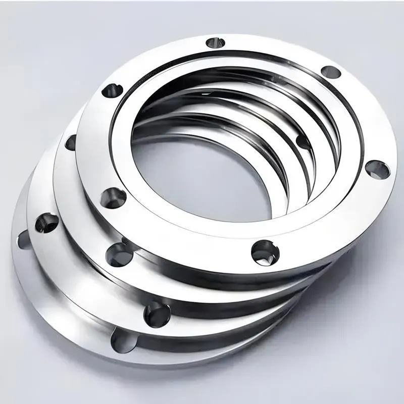
A flange—also referred to as a flange plate or rim—is a component used to connect shafts to one another, or, more commonly, to join the ends of pipes. Flanges are also utilized at the inlet and outlet ports of equipment to facilitate connections between two devices—for instance, the flange on a speed reducer. A "flange connection" or "flanged joint" refers to a detachable joint assembly comprising three interconnected elements—a flange, a gasket, and bolts—that together form a sealed structural unit. In the context of piping systems, a "pipe flange" specifically denotes a flange used for plumbing within the installation; when applied to equipment, it refers to the inlet or outlet flange of that specific device. Flanges feature a series of holes through which bolts are inserted to securely fasten the two flanges together, while a gasket placed between the flanges ensures a leak-proof seal. Flanges are broadly categorized into three types: threaded (screw-in) flanges, welded flanges, and clamp-type flanges. Flanges are invariably used in pairs; threaded flanges are suitable for low-pressure piping applications, whereas welded flanges are required for systems operating at pressures exceeding 4 kilograms per square centimeter. A sealing gasket is inserted between the two flange plates, which are then firmly secured using bolts. The thickness of a flange—as well as the specifications of the bolts used to fasten it—vary depending on the specific pressure rating required for the application. When connecting equipment such as water pumps or valves to piping systems, the corresponding connection points on these devices are often manufactured in the shape of a matching flange; this method of attachment is also referred to as a "flange connection." Generally, any connecting component that utilizes bolts to join and seal the perimeters of two flat surfaces—such as the joints in ventilation ducts—is termed a "flange"; such components may collectively be classified as "flange-type parts." However, since such a connection often constitutes merely a *portion* of a larger device—for instance, the interface between a flange and a water pump—it would be inappropriate to classify the entire water pump itself as a "flange-type part." Conversely, smaller components—such as valves—that feature such flanged interfaces may indeed be appropriately categorized as "flange-type parts."
-:-
For detailed product information, please contact sales.
-:
AISI Type M15 High Speed Tool Steel Flange Product Information
-:-
For detailed product information, please contact sales.
-:
AISI Type M15 High Speed Tool Steel Flange Synonyms
-:-
For detailed product information, please contact sales.
-:
AISI Type M15 High Speed Tool Steel Product Information
-:-
For detailed product information, please contact sales.
-:
# **Product Introduction: AISI Type M15 High-Cobalt Molybdenum High-Speed Tool Steel (UNS T11315)**
## **Overview**
AISI Type M15 is a **high-cobalt, high-vanadium molybdenum-based high-speed steel (HSS)** within the AISI M-series, representing one of the **highest performance grades** in conventional high-speed tool steels. Characterized by its **exceptional cobalt content (4.50-5.50%)** combined with high vanadium and molybdenum, M15 delivers superior **red hardness, wear resistance, and cutting performance** at elevated temperatures, making it ideal for demanding machining applications involving high-strength and high-temperature alloys.
**Key Advantages:**
- **Exceptional Red Hardness:** Maintains cutting edge at temperatures up to 600°C (1112°F)
- **Superior Wear Resistance:** High vanadium content provides excellent abrasion resistance
- **Good Thermal Conductivity:** Cobalt improves heat dissipation from cutting edge
- **Excellent Cutting Performance:** Optimized for difficult-to-machine materials
- **Good High-Temperature Strength:** Maintains structural integrity under thermal stress
**Primary Considerations:**
- **Reduced Toughness:** Higher hardness and cobalt content decrease impact resistance
- **Poor Grindability:** High vanadium carbides make grinding challenging
- **Higher Cost:** Premium price due to cobalt and alloy content
- **Processing Sensitivity:** Requires precise heat treatment control
## **International Designations & Standards**
| Standard System | Designation | Note |
|----------------|-------------|------|
| **AISI/SAE (USA)** | M15 | Primary specification |
| **UNS (USA)** | T11315 | Unified numbering system |
| **ASTM (USA)** | A600 | High-Speed Tool Steel Standard |
| **ISO (International)** | ~**HS10-4-3-10** | Similar high-cobalt composition (10%Co-4%Cr-3%V) |
| **DIN (Germany)** | ~1.3265 | High-cobalt high-speed steel |
| **JIS (Japan)** | ~SKH57 | Similar high-cobalt HSS |
| **BS (UK)** | ~**BM15** | High-cobalt molybdenum HSS |
| **GB (China)** | ~**W6Mo5Cr4V2Co5** | Similar cobalt-bearing HSS |
*Note: M15 represents a premium performance grade with significant cobalt addition, placing it among the highest-performing conventional high-speed steels.*
---
## **1. Chemical Composition (Typical, Weight %)**
M15's composition is engineered for maximum high-temperature performance with balanced carbide formers.
| Element | Content (%) | Role & Metallurgical Effect |
|---------|-------------|-----------------------------|
| **Carbon (C)** | 1.25 - 1.40 | High carbon content to balance extensive carbide formation and maintain matrix hardness. Critical for supporting hard vanadium carbides. |
| **Cobalt (Co)** | 4.50 - 5.50 | **Primary performance enhancer.** Increases red hardness, improves thermal conductivity, promotes secondary hardening, and enhances high-temperature strength. |
| **Molybdenum (Mo)** | 3.50 - 4.50 | Primary carbide former with tungsten, provides solid solution strengthening, and enables secondary hardening. |
| **Tungsten (W)** | 6.00 - 7.00 | Works synergistically with molybdenum to enhance hot hardness and wear resistance through tungsten carbide formation. |
| **Vanadium (V)** | 4.50 - 5.25 | **Critical wear element.** Forms extremely hard vanadium carbides (VC, V₄C₃) that provide exceptional abrasion resistance. High content challenges grindability. |
| **Chromium (Cr)** | 3.75 - 4.50 | Provides oxidation resistance, enhances hardenability, and contributes to secondary hardening response. |
| **Silicon (Si)** | 0.20 - 0.40 | Deoxidizer, strengthens ferrite matrix, improves tempering resistance. |
| **Manganese (Mn)** | 0.15 - 0.40 | Enhances hardenability and aids in deoxidation. |
| **Sulfur (S)** | ≤0.030 | Residual impurity. |
| **Phosphorus (P)** | ≤0.030 | Residual impurity. |
| **Iron (Fe)** | Balance | Matrix element. |
**Metallurgical Characteristics:**
- **Carbide Types:** MC (vanadium-rich), M₆C (molybdenum/tungsten), M₂₃C₆ (chromium)
- **Carbide Volume:** ~15-20% (very high due to C, V, and W content)
- **Primary Performance Drivers:** Co for red hardness, V for wear, W/Mo for hot strength
- **Austenitizing Temperature:** 1200-1240°C (high due to alloy content)
---
## **2. Physical & Mechanical Properties**
### **Physical Properties**
| Property | Typical Value | Conditions/Notes |
|----------|---------------|------------------|
| **Density** | 8.15 - 8.25 g/cm³ | At 20°C (68°F) |
| **Melting Range** | 1380 - 1430°C (2516 - 2606°F) | High melting point due to alloying |
| **Thermal Conductivity** | 25 - 30 W/m·K | At 20°C (68°F) - Improved by cobalt |
| **Specific Heat Capacity** | 410 - 450 J/kg·K | At 20°C (68°F) |
| **Coefficient of Thermal Expansion** | 10.2 - 11.2 × 10⁻⁶/K | 20-600°C (68-1112°F) range |
| **Electrical Resistivity** | 0.55 - 0.65 μΩ·m | At 20°C (68°F) |
| **Elastic Modulus** | 210 - 220 GPa (30.5 - 31.9 × 10⁶ psi) | At room temperature |
| **Magnetic Properties** | Ferromagnetic | Below Curie temperature (~800°C) |
### **Mechanical Properties (Properly Heat-Treated)**
| Property | Value Range | Heat Treatment Condition |
|----------|-------------|--------------------------|
| **Hardness (Annealed)** | 241 - 277 HB | Annealed condition |
| **Hardness (Hardened)** | 65 - 68 HRC | Triple tempered condition |
| **Hot Hardness (600°C)** | 58 - 61 HRC | After 4 hours at temperature |
| **Transverse Rupture Strength** | 3000 - 3600 MPa (435 - 522 ksi) | At 66-68 HRC |
| **Compressive Strength** | 3900 - 4500 MPa (566 - 653 ksi) | At 66-68 HRC |
| **Impact Toughness (Charpy)** | 8 - 15 J (5.9 - 11.1 ft·lb) | At 66-68 HRC - **Lower due to high hardness** |
| **Young's Modulus** | 210 - 220 GPa (30.5 - 31.9 × 10⁶ psi) | At room temperature |
| **Fatigue Strength** | 800 - 1000 MPa (116 - 145 ksi) | Rotating bending, 10⁷ cycles |
### **High-Temperature Performance Data**
| Temperature | Hardness (HRC) | Strength Retention | Relative Cutting Speed |
|-------------|----------------|-------------------|------------------------|
| **20°C (68°F)** | 66-68 | 100% | Baseline |
| **300°C (572°F)** | 63-65 | 95-97% | 120-140% vs M2 |
| **500°C (932°F)** | 59-62 | 89-92% | 140-160% vs M2 |
| **600°C (1112°F)** | 55-58 | 83-87% | 150-180% vs M2 |
| **650°C (1202°F)** | 50-53 | 75-80% | 130-150% vs M2 |
### **Grindability Characteristics**
- **Relative Grindability:** 40-50% (compared to M2 = 100%)
- **Wheel Wear:** 2-3x faster than M2 grinding
- **Power Requirement:** 30-50% higher than M2
- **Recommended Abrasives:** Diamond or CBN wheels essential
- **Coolant Requirement:** High-volume, high-pressure coolant system
---
## **3. Product Applications**
### **Primary Application Areas**
**1. High-Performance Cutting Tools:**
- End mills for high-temperature alloys (Inconel, Waspaloy)
- Drills for hardened steels and aerospace materials
- Turning tools for superalloys and hardened steels
- Thread mills and form cutters for difficult materials
**2. Specialized Machining Tools:**
- Broaches for high-volume production of tough materials
- Gear hobs for high-strength gear steels
- Reamers for precision holes in hardened components
- Milling cutters for abrasive composites
**3. Severe Service Tools:**
- Cutting tools for heat-treated components (45-55 HRC)
- Tools for interrupted cutting of high-strength alloys
- Machining tools for abrasive non-ferrous materials
- Cutting tools for high-silicon aluminum alloys
**4. Wear-Intensive Applications:**
- Cold work dies for abrasive materials
- Forming tools for high-volume production
- Punches and dies for hard materials
- Wear parts in high-temperature environments
### **Industry-Specific Applications**
| Industry | Typical M15 Components | Operating Conditions |
|----------|-----------------------|----------------------|
| **Aerospace** | End mills, drills for titanium/nickel alloys | High speed, dry or MQL machining |
| **Power Generation** | Turbine blade machining tools | High temperature, interrupted cuts |
| **Automotive (Performance)** | Tools for hardened components | High hardness workpieces |
| **Die & Mold** | Hard milling cutters | Machining pre-hardened mold steels |
| **Oil & Gas** | Tools for drilling components | Abrasive materials, high strength |
### **Cutting Performance Guidelines**
| Work Material | Cutting Speed (m/min) | Feed (mm/tooth) | Depth of Cut | Cooling Strategy |
|---------------|----------------------|-----------------|--------------|------------------|
| **Titanium Alloys** | 30-50 | 0.05-0.15 | 0.5-3.0mm | High-pressure coolant |
| **Nickel Superalloys** | 20-40 | 0.03-0.12 | 0.3-2.0mm | Copious emulsion |
| **Hardened Steels (45-55HRC)** | 40-70 | 0.08-0.20 | 0.5-3.0mm | Oil-based coolant |
| **Stainless Steels** | 40-60 | 0.08-0.18 | 0.5-3.0mm | Emulsion or oil |
| **High-Temp Alloys** | 15-35 | 0.02-0.10 | 0.2-1.5mm | High-pressure through-tool |
---
## **4. Heat Treatment Guidelines**
### **Annealing (Full Annealing)**
- **Temperature:** 850-880°C (1562-1616°F)
- **Soaking Time:** 3-5 hours at temperature
- **Cooling Rate:** ≤10°C/hr to 600°C, then air cool
- **Resulting Hardness:** 241-277 HB
- **Atmosphere:** Protective atmosphere essential
### **Stress Relieving**
- **After Rough Machining:** 650-700°C (1202-1292°F) for 2-3 hours
- **After Rough Grinding:** 550-600°C (1022-1112°F) for 1-2 hours
- **Cooling:** Slow furnace cool
### **Hardening (Precision Process)**
1. **Preheating:** **Critical** - Three-stage recommended
- **Stage 1:** 450-550°C (842-1022°F)
- **Stage 2:** 800-850°C (1472-1562°F)
- **Stage 3:** 1050-1100°C (1922-2012°F)
2. **Austenitizing:**
- **Temperature:** 1200-1240°C (2192-2264°F)
- **Soaking Time:** 3-6 minutes per 25mm (1 inch) of thickness
- **Atmosphere:** **Vacuum or salt bath strongly recommended**
- **Protection:** Pack carburizing or protective coatings if atmosphere not controlled
3. **Quenching Options:**
- **Oil Quench:** Fast oil, 40-60°C, vigorous agitation
- **Salt Bath Marquench:** 500-550°C, equalize, then air cool
- **Press Quenching:** For flat or form tools to minimize distortion
### **Tempering (Multiple Tempers Essential)**
- **Initial Temper:** Begin at 60-80°C (140-176°F) after quenching
- **Temperature:** 540-580°C (1004-1076°F)
- **Cycle:** Minimum 3 tempers, preferably 4 for complex tools
- **Duration:** 2-3 hours per temper for full transformation
- **Cooling:** Air cool completely between tempers
- **Final Hardness:** 65-68 HRC
- **Retained Austenite:** <3% after proper treatment
### **Sub-Zero Treatment (Highly Recommended)**
- **Temperature:** -80 to -120°C (-112 to -184°F)
- **Duration:** 3-6 hours minimum
- **Timing:** After quenching, before first temper
- **Benefits:** Maximum dimensional stability, full hardness potential
---
## **5. Machining & Grinding Characteristics**
### **Machinability (Annealed Condition)**
- **Relative Machinability:** 30-40% (compared to 1% carbon steel = 100%)
- **Tool Requirements:** Premium carbide grades only
- **Cutting Parameters:**
- **Turning:** 15-25 m/min (50-82 SFM) with carbide
- **Milling:** 10-20 m/min (33-66 SFM) with carbide
- **Drilling:** 5-10 m/min (16-33 SFM) with carbide
- **Chip Control:** Aggressive chip breakers required
- **Coolant:** High-performance synthetic or heavy-duty soluble oil
### **Grinding (Challenging - Requires Special Techniques)**
- **Abrasive Requirements:**
- **Diamond Wheels:** Resin or metal bond, 100-200 grit
- **CBN Wheels:** High concentration, vitrified bond
- **Not Recommended:** Conventional aluminum oxide wheels
- **Parameters:**
- **Wheel Speed:** 20-25 m/s (4000-5000 SFPM) for diamond/CBN
- **Downfeed:** 0.002-0.010 mm (0.00008-0.0004 in) per pass
- **Crossfeed:** 0.5-2.0 mm (0.02-0.08 in) per pass
- **Spark-out:** Multiple passes with zero infeed
- **Coolant:** High-pressure, high-volume synthetic coolant
- **Dressing:** Frequent dressing with diamond tools
### **Electrical Discharge Machining (EDM)**
- **Suitability:** Fair - requires careful parameter control
- **Electrodes:** Premium graphite or copper-tungsten
- **Parameters:** Low amperage, fine finishes
- **Post-EDM:** Stress relief and retempering recommended
- **White Layer:** Can be significant - requires removal by grinding
---
## **6. Comparative Analysis**
### **vs. Other High-Performance HSS Grades**
| Property | M15 | M42 | T15 | ASP2060 (PM) |
|----------|-----|-----|-----|---------------|
| **Cobalt Content** | 4.50-5.50% | 7.50-8.50% | 4.75-5.25% | 10.50% |
| **Vanadium Content** | 4.50-5.25% | 1.15-1.85% | 4.75-5.25% | 6.50% |
| **Red Hardness** | Excellent | Superior | Excellent | Outstanding |
| **Wear Resistance** | Outstanding | Good | Outstanding | Exceptional |
| **Toughness** | Poor | Fair | Very Poor | Good |
| **Grindability** | Very Poor | Poor | Extremely Poor | Fair |
| **Cost Factor** | 2.0-2.5x | 2.5-3.0x | 2.8-3.5x | 3.5-5.0x |
### **Performance Comparison in Critical Applications**
| Application | M15 Performance | Alternative Grades | Selection Criteria |
|-------------|-----------------|-------------------|-------------------|
| **High-Temp Alloys** | Excellent | M42, Powder HSS | Temperature >550°C |
| **Hard Milling** | Very Good | Powder HSS, Carbide | Workpiece >50 HRC |
| **High-Speed Machining** | Good | M42, Ceramic | Speed >200 m/min |
| **Abrasive Materials** | Outstanding | High-Vanadium PM | Severe abrasion |
| **Interrupted Cuts** | Fair | Toughness-optimized HSS | Severe interruption |
### **Economic Considerations**
- **Material Cost:** 200-250% of M2
- **Tool Life:** 150-400% of M2 in appropriate applications
- **Regrinding Cost:** 200-300% of M2 due to diamond wheels
- **Total Cost per Part:** Often lower for difficult materials despite higher initial cost
---
## **7. Surface Treatments & Coatings**
### **Essential Coatings for Optimal Performance**
1. **TiAlN (Aluminum Titanium Nitride):**
- Maximum temperature: 800-900°C
- Color: Dark violet/black
- Best for: High-temperature alloys, dry machining
2. **AlCrN (Aluminum Chromium Nitride):**
- Excellent for: Abrasive materials, hardened steels
- Higher hardness than TiAlN
- Good oxidation resistance
3. **Diamond-Like Carbon (DLC):**
- For: Non-ferrous materials, composites
- Extremely low friction coefficient
- Not for ferrous materials above 400°C
### **Coating Application Considerations**
- **Pre-coating Preparation:** Critical - surface finish <0.2μm Ra
- **Edge Preparation:** Honing essential (0.03-0.08mm radius)
- **Coating Thickness:** 2-5μm optimal
- **Post-coating:** Gentle handling to prevent coating damage
### **Coating Performance Benefits**
- **Tool Life Improvement:** 3-8x uncoated life
- **Cutting Speed Increase:** 30-100% possible
- **Surface Finish Improvement:** 1-3 roughness grades
- **Reliability:** More consistent performance across batches
---
## **8. Quality Control & Inspection**
### **Material Certification Requirements**
- **Full Traceability:** Heat number to final product
- **Chemical Analysis:** Complete spectrographic analysis
- **Microcleanliness:** ASTM E45, Method D, maximum inclusion rating
- **Carbide Structure:** Uniform distribution, appropriate size
### **Heat Treatment Verification**
- **Hardness Mapping:** Multiple points on complex tools
- **Microstructure:** Fine martensite, uniform secondary carbides
- **Retained Austenite:** X-ray diffraction measurement
- **Surface Integrity:** Decarburization <0.03mm, no oxidation
### **Tool Performance Validation**
- **Laboratory Testing:** Standardized cutting tests
- **Production Trials:** Under actual operating conditions
- **Wear Measurement:** Progressive wear monitoring
- **Failure Analysis:** Root cause investigation for premature failures
---
## **9. Technical Recommendations**
### **Design Guidelines for M15 Tools**
1. **Core Strength:** Adequate cross-sections to prevent breakage
2. **Edge Geometry:** Conservative angles for maximum edge strength
3. **Chip Control:** Optimized flute/rake geometry for chip evacuation
4. **Shank Design:** Positive locking features for secure clamping
### **Manufacturing Best Practices**
1. **Sequential Processing:** Rough machine → stress relieve → finish machine → heat treat → grind → coat
2. **Grinding Strategy:** Multiple operations with decreasing grit sizes
3. **Edge Treatment:** Honing after final grinding, before coating
4. **Quality Gates:** Inspection at each critical process step
### **Application Engineering**
1. **Machining Parameters:** Conservative starting parameters with progressive optimization
2. **Toolpath Strategy:** Climb milling, reduced radial engagement
3. **Workholding:** Maximum rigidity to minimize vibration
4. **Coolant Delivery:** Through-tool coolant preferred for deep operations
### **Common Failure Modes & Solutions**
| Failure Mode | Root Causes | Preventive Actions |
|--------------|-------------|-------------------|
| **Catastrophic Breakage** | Excessive load, vibration, edge weakness | Reduce feed, increase tool rigidity, hone edges |
| **Rapid Flank Wear** | Abrasive material, insufficient hardness | Apply wear-resistant coating, reduce speed |
| **Thermal Cracking** | Thermal cycling, insufficient cooling | Improve coolant delivery, use interrupted cuts |
| **Edge Chipping** | Micro-fractures, impact loading | Increase edge preparation, reduce feed per tooth |
### **Economic Optimization**
- **Tool Selection:** Match tool grade to material difficulty
- **Regrinding Strategy:** Maximum allowable regrinds based on core exposure
- **Inventory Management:** High-value tools require careful tracking
- **Performance Monitoring:** Continuous improvement based on tool life data
---
## **Disclaimer**
This technical datasheet provides comprehensive information about AISI Type M15 high-speed tool steel based on industry standards and high-performance applications. Actual properties and performance may vary depending on:
1. **Manufacturer's specific metallurgical practices** and quality systems
2. **Precise heat treatment execution** and equipment capabilities
3. **Exact application conditions** and machining parameters
4. **Tool design sophistication** and manufacturing precision
**Critical Application Notes:**
- M15 represents a premium solution for specific challenging applications
- Not cost-effective for general-purpose machining
- Requires specialized grinding equipment and expertise
- Performance maximized with appropriate coatings and application engineering
For mission-critical applications, consult with:
- Materials engineering specialists
- Tool design experts
- Application engineers
- Coating technology providers
Reference current standards including:
- ASTM A600: Standard Specification for Tool Steel High Speed
- ISO 4957: Tool steels
- Manufacturer's technical data and processing guidelines
This information represents current industry knowledge and is subject to revision as technology advances. Always validate requirements with technical experts for specific applications.
-:-
For detailed product information, please contact sales.
-:
AISI Type M15 High Speed Tool Steel Specification
Dimensions
Size:
Diameter 20-1000 mm Length <6717 mm
Size:We can customized as required
Standard:
Per your request or drawing
We can customized as required
Properties(Theoretical)
Chemical Composition
-:-
For detailed product information, please contact sales.
-:
AISI Type M15 High Speed Tool Steel Properties
-:-
For detailed product information, please contact sales.
-:
Applications of AISI Type M15 High Speed Tool Steel Flange
-:-
For detailed product information, please contact sales.
-:
Chemical Identifiers AISI Type M15 High Speed Tool Steel Flange
-:-
For detailed product information, please contact sales.
-:
Packing of AISI Type M15 High Speed Tool Steel Flange
-:-
For detailed product information, please contact sales.
-:
Standard Packing:
-:-
For detailed product information, please contact sales.
-:
Typical bulk packaging includes palletized plastic 5 gallon/25 kg. pails, fiber and Steel Flange drums to 1 ton super sacks in full container (FCL) or truck load (T/L) quantities. Research and sample quantities and hygroscopic, oxidizing or other air sensitive materials may be packaged under argon or vacuum. Solutions are packaged in polypropylene, plastic or glass jars up to palletized 3188 gallon liquid totes Special package is available on request. E FORUs’ is carefully handled to minimize damage during storage and transportation and to preserve the quality of our products in their original condition