PSM Industries,Ferro-TiC® SK Impact Resistant Tool Steel Flange
Product Code : FL-Steel-1752-CU
We provide PSM Industries,Ferro-TiC® SK Impact Resistant Tool Steel Flange Manufacturing types: Forging, Casting, Cutting, Rolling.We can manufacture in accordance with these standards.GB/T 9112–9124-2010 Steel Pipe Flanges , JB Series , HG Series, ASME B16.5, BS4504, DIN , JIS,CBM,etc
1,We Manufacturing processes are primarily classified into four types:
1:Forging,
2:Casting,
3:Cutting,
4:Rolling.
2,We can manufacture in accordance with these standards.
Standards:
GB Series (Chinese Standards), JB Series (Machinery Standards), HG Series (Chemical Industry Standards), ASME B16.5 (American Standards), BS4504 (British Standards), DIN (German Standards), and JIS (Japanese Standards).
Internationally, there are two primary systems of pipe flange standards: the European system, represented by the German DIN standards (including those of the former Soviet Union), and the American system, represented by the US ANSI pipe flange standards. Other common standards include: the Chinese Ministry of Machinery Industry standards (JB series), the Ministry of Chemical Industry standards (HG series), the Chinese National Standard *GB/T 9112–9124-2010 Steel Pipe Flanges*, as well as US standards (ASME B16.5), British standards (BS4504), German standards (DIN), Japanese standards (JIS), and marine standards (CBM), among others.
The nominal pressure ratings for the PN series are designated by "PN" and comprise the following nine levels: PN2.5, PN6, PN10, PN16, PN25, PN40, PN63, PN100, and PN160.
The nominal pressure ratings for the Class series are designated by "Class" and comprise the following six levels: Class150, Class300, Class600, Class900, Class1500, and Class2500.
Flange Classification
1. **According to Chemical Industry Standards:** Flanges are classified as follows:
Plate Flat Welding Flange (PL), Necked Flat Welding Flange (SO), Necked Butt Welding Flange (WN), Integral Flange (IF), Socket Welding Flange (SW), Threaded Flange (Th), Butt Welding Ring Loose Flange (PJ/SE), Blind Flange (BL), Flat Welding Ring Loose Flange (PJ/PJ), and Lined Blind Flange (BL(s)).
2. **According to Petrochemical (SH) Industry Standards:** Flanges are classified as follows:
Threaded Flange (PL), Butt Welding Flange (WN), Flat Welding Flange (SO), Socket Welding Flange (SW), Loose Flange (LJ), and Blind Flange (no specific designation).
3. **According to Machinery (JB) Industry Standards:** Flanges are classified as follows:
Integral Flange, Butt Welding Flange, Plate Flat Welding Flange, Butt Welding Ring Plate Loose Flange, Flat Welding Ring Plate Loose Flange, Lap Joint Ring Plate Loose Flange, and Blind Flange.
4. **According to Connection Method/Type:** Flanges are classified as follows:
Plate Flat Welding Flange, Necked Flat Welding Flange, Necked Butt Welding Flange, Socket Welding Flange, Threaded Flange, Blind Flange, Necked Butt Welding Ring Loose Flange, Flat Welding Ring Loose Flange, Ring-Type Joint (RTJ) Flange and Blind Flange, Large-Diameter Plate Flange, Large-Diameter High-Neck Flange, Figure-8 Blind Plate, Butt Welding Ring Loose Flange, etc.
5. **According to the Component Being Connected:** Flanges can be classified into Vessel Flanges and Pipe Flanges.
6. **According to Structural Type:** Flanges include Integral Flanges, Threaded Flanges, Flat Welding Flanges, Butt Welding Flanges, Lap Joint (Loose/Swivel) Flanges, and Blind Flanges.
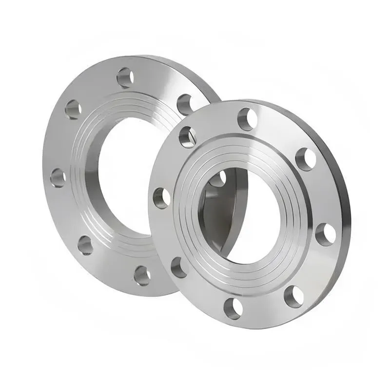
A flange—also referred to as a flange plate or rim—is a component used to connect shafts to one another, or, more commonly, to join the ends of pipes. Flanges are also utilized at the inlet and outlet ports of equipment to facilitate connections between two devices—for instance, the flange on a speed reducer. A "flange connection" or "flanged joint" refers to a detachable joint assembly comprising three interconnected elements—a flange, a gasket, and bolts—that together form a sealed structural unit. In the context of piping systems, a "pipe flange" specifically denotes a flange used for plumbing within the installation; when applied to equipment, it refers to the inlet or outlet flange of that specific device. Flanges feature a series of holes through which bolts are inserted to securely fasten the two flanges together, while a gasket placed between the flanges ensures a leak-proof seal. Flanges are broadly categorized into three types: threaded (screw-in) flanges, welded flanges, and clamp-type flanges. Flanges are invariably used in pairs; threaded flanges are suitable for low-pressure piping applications, whereas welded flanges are required for systems operating at pressures exceeding 4 kilograms per square centimeter. A sealing gasket is inserted between the two flange plates, which are then firmly secured using bolts. The thickness of a flange—as well as the specifications of the bolts used to fasten it—vary depending on the specific pressure rating required for the application. When connecting equipment such as water pumps or valves to piping systems, the corresponding connection points on these devices are often manufactured in the shape of a matching flange; this method of attachment is also referred to as a "flange connection." Generally, any connecting component that utilizes bolts to join and seal the perimeters of two flat surfaces—such as the joints in ventilation ducts—is termed a "flange"; such components may collectively be classified as "flange-type parts." However, since such a connection often constitutes merely a *portion* of a larger device—for instance, the interface between a flange and a water pump—it would be inappropriate to classify the entire water pump itself as a "flange-type part." Conversely, smaller components—such as valves—that feature such flanged interfaces may indeed be appropriately categorized as "flange-type parts."
-:-
For detailed product information, please contact sales.
-:
PSM Industries Ferro-TiC® SK Impact Resistant Tool Steel Flange Product Information
-:-
For detailed product information, please contact sales.
-:
PSM Industries Ferro-TiC® SK Impact Resistant Tool Steel Flange Synonyms
-:-
For detailed product information, please contact sales.
-:
PSM Industries Ferro-TiC® SK Impact Resistant Tool Steel Product Information
-:-
For detailed product information, please contact sales.
-:
# **PSM Industries Ferro-TiC® SK | Impact-Resistant Tool Steel Metal Matrix Composite**
## **Overview**
PSM Industries' Ferro-TiC® SK is a revolutionary impact-resistant metal matrix composite engineered specifically for applications demanding exceptional toughness alongside superior wear resistance. Representing a significant breakthrough in tool steel technology, this material uniquely combines a shock-resistant tool steel matrix (based on S7/1.2357 chemistry) with a strategically controlled dispersion of titanium carbide (TiC) particles. Manufactured through proprietary powder metallurgy processes, Ferro-TiC® SK achieves what was previously considered impossible: **maintaining the high impact toughness of premium shock steels while dramatically improving wear resistance through TiC reinforcement**. It is specifically designed for demanding tooling applications where brittle fracture, chipping, or catastrophic failure under impact loading are primary concerns, while still requiring extended wear life.
## **Key Features:**
- **Unprecedented Toughness-Wear Balance:** Engineered to provide significantly higher wear resistance than conventional shock steels while maintaining impact toughness far superior to standard Ferro-TiC® grades
- **Optimized for Impact Loading:** Specifically designed matrix chemistry and carbide distribution to absorb energy and resist crack propagation under shock conditions
- **Enhanced Fatigue Resistance:** Superior resistance to fatigue failure under cyclic impact loading compared to both conventional tool steels and cemented carbides
- **Excellent Machinability:** Maintains good machinability in the annealed state despite TiC reinforcement
- **Dimensional Stability:** Minimal distortion during heat treatment enables production of precision components
- **Isotropic Properties:** Uniform PM microstructure ensures consistent performance regardless of load direction
- **Broad Hardness Range:** Can be heat treated to various hardness levels to optimize toughness or wear resistance for specific applications
---
## **Material Specifications: Ferro-TiC® SK**
### **1. Chemical Composition (Typical, wt%)**
The SK composition is carefully engineered to maximize toughness while providing adequate wear resistance through controlled TiC reinforcement:
| Element | Content Range (wt%) | Function & Notes |
|---------|---------------------|------------------|
| **Iron (Fe)** | Balance | Matrix base metal |
| **Titanium (Ti)** | 4 - 8% | Forms TiC reinforcement (lower volume than wear grades) |
| **Carbon (C)** | 0.8 - 1.2% | Balanced for matrix properties and carbide formation |
| **Chromium (Cr)** | 3.0 - 3.5% | Provides hardenability and mild corrosion resistance |
| **Molybdenum (Mo)** | 1.3 - 1.8% | Enhances toughness and hardenability |
| **Silicon (Si)** | 0.2 - 0.5% | Deoxidizer and strengthening element |
| **Manganese (Mn)** | 0.2 - 0.5% | Improves hardenability and strength |
| **Vanadium (V)** | 0.1 - 0.3% | Optional addition for grain refinement |
*Note: The "SK" designation indicates Shock/Impact grade. TiC volume fraction is approximately 15-25% by volume – intentionally lower than wear-focused grades to preserve toughness. The matrix is specifically designed for high impact energy absorption.*
### **2. Physical & Mechanical Properties**
#### **Standard Heat Treatment Condition (Tempered @ 540°C / 1000°F):**
| Property | Typical Value | Test Standard |
|----------|---------------|----------------|
| **Density** | 7.5 - 7.7 g/cm³ | ASTM B311 |
| **Hardness** | 54 - 58 HRC | ASTM E18 |
| **0.2% Yield Strength** | 1,800 - 2,100 MPa | ASTM E8 |
| **Tensile Strength** | 2,100 - 2,400 MPa | ASTM E8 |
| **Elongation** | 8 - 12% | ASTM E8 |
| **Reduction of Area** | 35 - 45% | ASTM E8 |
| **Modulus of Elasticity** | 205 - 215 GPa | ASTM E111 |
#### **Impact Properties (Charpy V-Notch, Room Temperature):**
| Condition | Impact Energy | Notes |
|-----------|---------------|-------|
| **Longitudinal** | 40 - 60 J | Excellent for composite material |
| **Transverse** | 35 - 55 J | Minimal anisotropy |
| **Comparison to S7** | 70-80% of S7 | With 3-5× better wear resistance |
| **Comparison to D2** | 4-6× higher | At similar hardness |
#### **Fatigue Properties:**
- **Fatigue Strength (10⁷ cycles):** 750 - 900 MPa
- **Fatigue Crack Growth Rate:** Significantly lower than conventional tool steels
- **Fatigue Ratio (σ_fat/UTS):** 0.35 - 0.40
#### **Properties at Various Hardness Levels:**
| Tempering Temperature | Resulting Hardness | Impact Energy | Compressive Strength |
|----------------------|-------------------|---------------|----------------------|
| 200°C (390°F) | 58-60 HRC | 25-35 J | 2,800-3,200 MPa |
| 400°C (750°F) | 56-58 HRC | 35-45 J | 2,500-2,900 MPa |
| 540°C (1000°F) | 54-56 HRC | 40-60 J | 2,200-2,600 MPa |
| 600°C (1110°F) | 50-52 HRC | 55-70 J | 1,900-2,300 MPa |
### **3. Applicable & Reference Standards**
Ferro-TiC® SK is engineered to meet the demanding requirements of impact tool applications:
- **ASTM A681 (Grade S7):** Primary reference for shock-resistant properties
- **ISO 4957 (Grade X30WCrV9-3):** Cold work shock steel equivalent
- **DIN 1.2357:** German standard for shock-resistant tool steel
- **JIS G4404 (Grade SKD?):** Reference for shock applications
- **ISO 4957 (Grade S5):** Alternative shock steel reference
- **ASTM A600:** High-speed steel standards (for comparison)
- **Custom OEM Specifications:** Developed for specific punching, shearing, and forming applications
---
## **Product Applications**
### **Punching and Shearing:**
- **Heavy-Duty Punches:** For thick materials and high-strength alloys
- **Shear Blades:** For metal cutting and slitting operations
- **Notching Tools:** For intricate cutting operations requiring toughness
- **Trimming Dies:** For flash removal in forging and casting
### **Cold Forming and Heading:**
- **Cold Heading Dies:** For bolt and fastener production
- **Extrusion Punches:** For backward and forward extrusion
- **Nail Making Dies:** For high-impact wire forming
- **Swaging Tools:** For reduction and shaping operations
### **Mining and Construction Tools:**
- **Drill Bits and Inserts:** For percussive drilling applications
- **Pick Tools:** For mining and road planning
- **Cutter Teeth:** For excavation and tunneling equipment
- **Demolition Tools:** For concrete breaking and processing
### **Automotive and Aerospace:**
- **High-Strength Sheet Metal Forming:** For advanced high-strength steels (AHSS)
- **Trim and Pierce Dies:** For structural components
- **Mandrels and Arbors:** For tube forming and expansion
- **Locating Pins and Bushings:** For high-wear fixture applications
### **Specialty Tooling:**
- **Bolt Cutters and Pliers:** For cutting edges requiring wear and toughness
- **Chisels and Pry Bars:** For industrial maintenance tools
- **Agricultural Tools:** For cutting and processing equipment
- **Food Processing Blades:** For bones and frozen products
---
## **Processing Guidelines**
### **Heat Treatment:**
1. **Annealing:** 840-860°C (1545-1580°F), slow cool to 500°C (930°F), furnace cool
- Resulting hardness: 200-230 HB (optimal for machining)
2. **Hardening:**
- **Preheat:** 650°C (1200°F) and 800°C (1470°F)
- **Austenitizing:** 940-970°C (1725-1780°F) for 30-45 minutes
- **Quenching:** Oil quench preferred; forced air quench acceptable for simple shapes
3. **Tempering:**
- **Immediate Tempering:** Required within 1 hour of quenching
- **Temperature Range:** 200-600°C (390-1110°F) depending on desired properties
- **Double Tempering:** Recommended for optimal toughness and stress relief
- **Cryogenic Treatment:** Optional between tempers for maximum dimensional stability
### **Machining:**
- **Annealed Condition:** 200-230 HB (excellent machinability for a composite)
- **Cutting Tools:** Carbide tools recommended; HSS tools acceptable with proper parameters
- **Cutting Speeds:** 60-80% of standard S7 rates
- **Feed Rates:** Moderate feeds preferred
- **Coolant:** Recommended for all operations
### **Grinding and Finishing:**
- **Grinding Wheels:** Aluminum oxide or CBN wheels suitable
- **Parameters:** Use lower speeds and adequate coolant to prevent burning
- **EDM:** Excellent results with proper parameters and multiple skim cuts
- **Polishing:** Good polishability for a composite material
### **Welding and Repair:**
- **Weldability:** Good with proper procedures
- **Recommended Process:** TIG welding with matching filler
- **Preheat:** 300-350°C (570-660°F)
- **Post-Weld Heat Treatment:** Re-temper immediately after welding
- **Applications:** Suitable for repair and build-up of cutting edges
---
## **Performance Advantages**
### **Compared to Conventional Shock Steels (S7, S5):**
- **Wear Resistance:** 3-5× improvement at similar hardness levels
- **Abrasion Resistance:** Dramatically better in abrasive applications
- **Edge Retention:** Significantly longer cutting life between regrinds
- **Gallling Resistance:** Improved performance in adhesive wear situations
- **Dimensional Stability:** Better resistance to distortion during heat treatment
### **Compared to Wear-Resistant Tool Steels (D2, M2):**
- **Impact Toughness:** 4-10× higher at comparable hardness
- **Fatigue Resistance:** Superior performance under cyclic loading
- **Crack Propagation Resistance:** Much more resistant to catastrophic failure
- **Machinability:** Better in annealed condition
- **Grindability:** Superior with less risk of burning
### **Economic Benefits:**
- **Extended Tool Life:** Typically 2-4× longer than conventional shock steels
- **Reduced Downtime:** Fewer tool changes and catastrophic failures
- **Higher Productivity:** Ability to run at higher speeds or with more abrasive materials
- **Reduced Tool Inventory:** One material can replace multiple specialized grades
- **Lower Maintenance Costs:** Less frequent sharpening and repair
### **Design Advantages:**
- **Thinner Sections Possible:** Higher strength allows more efficient designs
- **Smaller Tooling:** Higher performance enables compact tool designs
- **Combined Functions:** Can replace assemblies of multiple materials
- **Improved Safety:** Reduced risk of catastrophic tool failure
---
## **Quality Assurance**
- **Ultrasonic Inspection:** Standard for critical components
- **Impact Testing:** Batch testing of Charpy specimens
- **Hardness Verification:** Full cross-section mapping available
- **Microstructural Analysis:** Carbide distribution and matrix evaluation
- **Dimensional Certification:** To customer specifications
- **Traceability:** Full material and process history
- **Performance Testing:** Application-specific testing protocols available
---
## **Technical Support Services**
PSM Industries provides comprehensive support for Ferro-TiC® SK applications:
- **Application Engineering:** Material selection and design optimization
- **Failure Analysis:** Root cause determination for tool failures
- **Heat Treatment Development:** Customized cycles for specific requirements
- **Field Performance Monitoring:** Ongoing technical support
- **Training Programs:** Technical seminars and workshops
---
## **Comparative Performance Matrix**
| Material | Relative Impact Toughness | Relative Wear Resistance | Optimal Hardness Range | Primary Applications |
|----------|--------------------------|--------------------------|------------------------|----------------------|
| **Ferro-TiC® SK** | 100 (Reference) | 100 (Reference) | 54-58 HRC | Balanced impact/wear |
| **S7 Shock Steel** | 120-140 | 20-25 | 54-58 HRC | Pure impact applications |
| **D2 Cold Work** | 15-25 | 80-90 | 58-62 HRC | Wear-focused applications |
| **M2 HSS** | 20-30 | 90-100 | 62-66 HRC | High-speed cutting |
| **Cemented Carbide** | 10-20 | 300-400 | 85-92 HRA | Extreme wear, no impact |
**Typical Application Replacement Guide:**
- **Replacing S7:** When wear is limiting tool life more than toughness
- **Replacing D2/M2:** When chipping or breakage is the failure mode
- **Replacing Carbide:** When impact loading prevents carbide use
- **New Designs:** When optimal balance of properties is required
---
**Disclaimer:** The information contained herein is based on typical laboratory data and field performance. Actual results may vary depending on specific application conditions, heat treatment procedures, component design, and operating parameters. This document is for informational purposes only and does not constitute a warranty or guarantee of performance. Users should conduct appropriate testing for their specific applications. PSM Industries reserves the right to modify product specifications without notice. For critical applications, consultation with PSM technical personnel is essential.
-:-
For detailed product information, please contact sales.
-:
PSM Industries Ferro-TiC® SK Impact Resistant Tool Steel Specification
Dimensions
Size:
Diameter 20-1000 mm Length <7105 mm
Size:We can customized as required
Standard:
Per your request or drawing
We can customized as required
Properties(Theoretical)
Chemical Composition
-:-
For detailed product information, please contact sales.
-:
PSM Industries Ferro-TiC® SK Impact Resistant Tool Steel Properties
-:-
For detailed product information, please contact sales.
-:
Applications of PSM Industries Ferro-TiC® SK Impact Resistant Tool Steel Flange
-:-
For detailed product information, please contact sales.
-:
Chemical Identifiers PSM Industries Ferro-TiC® SK Impact Resistant Tool Steel Flange
-:-
For detailed product information, please contact sales.
-:
Packing of PSM Industries Ferro-TiC® SK Impact Resistant Tool Steel Flange
-:-
For detailed product information, please contact sales.
-:
Standard Packing:
-:-
For detailed product information, please contact sales.
-:
Typical bulk packaging includes palletized plastic 5 gallon/25 kg. pails, fiber and Steel Flange drums to 1 ton super sacks in full container (FCL) or truck load (T/L) quantities. Research and sample quantities and hygroscopic, oxidizing or other air sensitive materials may be packaged under argon or vacuum. Solutions are packaged in polypropylene, plastic or glass jars up to palletized 3576 gallon liquid totes Special package is available on request. E FORUs’ is carefully handled to minimize damage during storage and transportation and to preserve the quality of our products in their original condition