1,We Manufacturing processes are primarily classified into four types:
1:Forging,
2:Casting,
3:Cutting,
4:Rolling.
2,We can manufacture in accordance with these standards.
Standards:
GB Series (Chinese Standards), JB Series (Machinery Standards), HG Series (Chemical Industry Standards), ASME B16.5 (American Standards), BS4504 (British Standards), DIN (German Standards), and JIS (Japanese Standards).
Internationally, there are two primary systems of pipe flange standards: the European system, represented by the German DIN standards (including those of the former Soviet Union), and the American system, represented by the US ANSI pipe flange standards. Other common standards include: the Chinese Ministry of Machinery Industry standards (JB series), the Ministry of Chemical Industry standards (HG series), the Chinese National Standard *GB/T 9112–9124-2010 Steel Pipe Flanges*, as well as US standards (ASME B16.5), British standards (BS4504), German standards (DIN), Japanese standards (JIS), and marine standards (CBM), among others.
The nominal pressure ratings for the PN series are designated by "PN" and comprise the following nine levels: PN2.5, PN6, PN10, PN16, PN25, PN40, PN63, PN100, and PN160.
The nominal pressure ratings for the Class series are designated by "Class" and comprise the following six levels: Class150, Class300, Class600, Class900, Class1500, and Class2500.
Flange Classification
1. **According to Chemical Industry Standards:** Flanges are classified as follows:
Plate Flat Welding Flange (PL), Necked Flat Welding Flange (SO), Necked Butt Welding Flange (WN), Integral Flange (IF), Socket Welding Flange (SW), Threaded Flange (Th), Butt Welding Ring Loose Flange (PJ/SE), Blind Flange (BL), Flat Welding Ring Loose Flange (PJ/PJ), and Lined Blind Flange (BL(s)).
2. **According to Petrochemical (SH) Industry Standards:** Flanges are classified as follows:
Threaded Flange (PL), Butt Welding Flange (WN), Flat Welding Flange (SO), Socket Welding Flange (SW), Loose Flange (LJ), and Blind Flange (no specific designation).
3. **According to Machinery (JB) Industry Standards:** Flanges are classified as follows:
Integral Flange, Butt Welding Flange, Plate Flat Welding Flange, Butt Welding Ring Plate Loose Flange, Flat Welding Ring Plate Loose Flange, Lap Joint Ring Plate Loose Flange, and Blind Flange.
4. **According to Connection Method/Type:** Flanges are classified as follows:
Plate Flat Welding Flange, Necked Flat Welding Flange, Necked Butt Welding Flange, Socket Welding Flange, Threaded Flange, Blind Flange, Necked Butt Welding Ring Loose Flange, Flat Welding Ring Loose Flange, Ring-Type Joint (RTJ) Flange and Blind Flange, Large-Diameter Plate Flange, Large-Diameter High-Neck Flange, Figure-8 Blind Plate, Butt Welding Ring Loose Flange, etc.
5. **According to the Component Being Connected:** Flanges can be classified into Vessel Flanges and Pipe Flanges.
6. **According to Structural Type:** Flanges include Integral Flanges, Threaded Flanges, Flat Welding Flanges, Butt Welding Flanges, Lap Joint (Loose/Swivel) Flanges, and Blind Flanges.
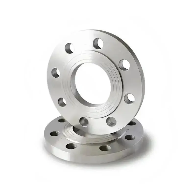
A flange—also referred to as a flange plate or rim—is a component used to connect shafts to one another, or, more commonly, to join the ends of pipes. Flanges are also utilized at the inlet and outlet ports of equipment to facilitate connections between two devices—for instance, the flange on a speed reducer. A "flange connection" or "flanged joint" refers to a detachable joint assembly comprising three interconnected elements—a flange, a gasket, and bolts—that together form a sealed structural unit. In the context of piping systems, a "pipe flange" specifically denotes a flange used for plumbing within the installation; when applied to equipment, it refers to the inlet or outlet flange of that specific device. Flanges feature a series of holes through which bolts are inserted to securely fasten the two flanges together, while a gasket placed between the flanges ensures a leak-proof seal. Flanges are broadly categorized into three types: threaded (screw-in) flanges, welded flanges, and clamp-type flanges. Flanges are invariably used in pairs; threaded flanges are suitable for low-pressure piping applications, whereas welded flanges are required for systems operating at pressures exceeding 4 kilograms per square centimeter. A sealing gasket is inserted between the two flange plates, which are then firmly secured using bolts. The thickness of a flange—as well as the specifications of the bolts used to fasten it—vary depending on the specific pressure rating required for the application. When connecting equipment such as water pumps or valves to piping systems, the corresponding connection points on these devices are often manufactured in the shape of a matching flange; this method of attachment is also referred to as a "flange connection." Generally, any connecting component that utilizes bolts to join and seal the perimeters of two flat surfaces—such as the joints in ventilation ducts—is termed a "flange"; such components may collectively be classified as "flange-type parts." However, since such a connection often constitutes merely a *portion* of a larger device—for instance, the interface between a flange and a water pump—it would be inappropriate to classify the entire water pump itself as a "flange-type part." Conversely, smaller components—such as valves—that feature such flanged interfaces may indeed be appropriately categorized as "flange-type parts."
-:-
For detailed product information, please contact sales.
-:
3D Systems LaserForm® 316L (A) AFTER STRESS RELIEF Stainless Steel Flange Material Product Information
-:-
For detailed product information, please contact sales.
-:
3D Systems LaserForm® 316L (A) AFTER STRESS RELIEF Stainless Steel Flange Material Synonyms
-:-
For detailed product information, please contact sales.
-:
3D Systems LaserForm® 316L (A) AFTER STRESS RELIEF Stainless Steel Material Product Information
-:-
For detailed product information, please contact sales.
-:
# **3D Systems LaserForm® 316L (A) AFTER STRESS RELIEF Stainless Steel Material**
## **Product Overview**
**3D Systems LaserForm® 316L (A) AFTER STRESS RELIEF** is a premium austenitic stainless steel powder material specifically engineered for Direct Metal Printing (DMP) technology, processed to include a mandatory **stress relief heat treatment** after building. This material variant of the industry-standard 316L alloy is optimized for additive manufacturing applications where **dimensional stability, corrosion resistance, and reduced residual stresses** are critical requirements. The stress-relieved condition ensures minimal part distortion during subsequent machining or in service, making it ideal for precision components in medical, aerospace, and chemical processing industries.
---
## **TECHNICAL SPECIFICATIONS**
### **Manufacturing & Processing Specification**
| Parameter | Specification |
|-----------|---------------|
| **Primary Process** | Direct Metal Printing (DMP) / Laser Powder Bed Fusion (LPBF) |
| **Post-Process Treatment** | **Mandatory Stress Relief** per defined thermal cycle |
| **Compatible Systems** | 3D Systems ProX DMP 200/300, DMP Factory 350/500/850 |
| **Build Volume** | Up to 500 × 500 × 500 mm (system dependent) |
| **Layer Thickness** | 30 μm (high detail), 40 μm (standard), 60 μm (production) |
| **Atmosphere Control** | High-purity argon (< 50 ppm O₂) |
| **Build Plate Temperature** | 100-120°C (recommended for 316L) |
### **Material Composition (wt%, Powder Specification)**
| Element | Target Range | Metallurgical Function in AM-Stress Relieved |
|---------|--------------|-----------------------------------|
| **Chromium (Cr)** | 16.5-18.5 | Primary corrosion resistance, passive film formation |
| **Nickel (Ni)** | 10.0-13.0 | Austenite stabilization, ductility |
| **Molybdenum (Mo)** | 2.0-2.5 | **Enhanced pitting resistance**, strength |
| **Manganese (Mn)** | 1.0-2.0 | Austenite stabilizer, deoxidizer |
| **Silicon (Si)** | 0.50-0.80 | Deoxidizer, fluidity control |
| **Carbon (C)** | ≤ 0.025 | **Extra-low carbon for AM processability** |
| **Nitrogen (N)** | ≤ 0.10 | Austenite stabilizer, strength enhancement |
| **Copper (Cu)** | ≤ 0.50 | Optional for specific corrosion resistance |
| **Phosphorus (P)** | ≤ 0.020 | Impurity control |
| **Sulfur (S)** | ≤ 0.010 | Impurity control |
| **Iron (Fe)** | Balance | Matrix |
*Optimized for stress relief response and minimal δ-ferrite formation*
### **Powder Characteristics (Virgin Powder)**
| Property | Specification | Test Method |
|----------|---------------|-------------|
| **Particle Size Distribution** | D10: 20-25 μm, D50: 30-38 μm, D90: 45-55 μm | ASTM B822 |
| **Particle Morphology** | > 95% spherical, satellite-controlled | SEM Analysis |
| **Apparent Density** | 4.1-4.4 g/cm³ | ASTM B212 |
| **Tap Density** | 4.9-5.2 g/cm³ | ASTM B527 |
| **Flowability** | 23-28 s/50g | Hall Flowmeter |
| **Oxygen Content** | < 400 ppm | Inert gas fusion |
| **Moisture Content** | < 0.02% | Karl Fischer |
| **Recyclability Index** | > 80% after 5 cycles | 3D Systems Protocol |
---
## **STRESS RELIEF PROTOCOL**
### **Standard Stress Relief Treatment**
| Parameter | Specification |
|-----------|---------------|
| **Temperature** | 470°C ± 10°C (878°F ± 18°F) |
| **Hold Time** | 2 hours minimum, plus 1 hour per 25 mm thickness |
| **Heating Rate** | ≤ 100°C/hour (212°F/hour) to 300°C, then ≤ 50°C/hour above |
| **Atmosphere** | Inert (Argon/Nitrogen) or air with controlled dew point |
| **Cooling Rate** | ≤ 50°C/hour (122°F/hour) to 300°C, then furnace or air cool |
| **Maximum Load Temperature** | 300°C (572°F) for loading/unloading |
### **Microstructural Changes After Stress Relief**
- **Residual Stress Reduction:** 70-85% reduction from as-built state
- **Grain Structure:** No significant grain growth (ASTM 7-9 maintained)
- **Phase Stability:** Fully austenitic, δ-ferrite < 1% if present
- **Precipitate Formation:** Minimal carbide precipitation at grain boundaries
- **Dislocation Density:** Significant reduction, improved ductility
- **Dimensional Stability:** Typical dimensional change < 0.05%
---
## **MECHANICAL PROPERTIES (After Stress Relief)**
### **Tensile Properties (ASTM E8/E8M, Room Temperature)**
| Orientation | Ultimate Tensile Strength | Yield Strength (0.2%) | Elongation | Reduction of Area |
|-------------|---------------------------|-----------------------|------------|-------------------|
| **Horizontal (XY)** | 580-650 MPa | 480-550 MPa | 40-50% | 60-70% |
| **Vertical (Z)** | 560-620 MPa | 460-530 MPa | 35-45% | 55-65% |
| **45° Diagonal** | 570-630 MPa | 470-540 MPa | 38-48% | 58-68% |
*Note: Properties represent typical values after standard stress relief treatment*
### **Comprehensive Mechanical Properties**
| Property | After Stress Relief | Test Standard | Notes |
|----------|---------------------|---------------|-------|
| **Hardness** | 180-220 HV (75-85 HRB) | ASTM E92/E18 | Consistent throughout |
| **Impact Toughness** | > 100 J | ASTM E23 | Charpy V-notch, 22°C |
| **Fatigue Strength** | 280-320 MPa | ASTM E466 | R = -1, 10⁷ cycles |
| **Young's Modulus** | 190-200 GPa | ASTM E111 | |
| **Shear Strength** | 380-420 MPa | ASTM B831 | |
| **Compressive Strength** | 650-750 MPa | ASTM E9 | |
| **Bearing Strength** | 850-950 MPa | ASTM E238 | |
| **Fracture Toughness (KIC)** | > 150 MPa√m | ASTM E399 | CT specimens |
### **Cryogenic & Elevated Temperature Properties**
| Temperature | Yield Strength | Impact Toughness | Notes |
|-------------|---------------|------------------|-------|
| **-196°C (-321°F)** | 850-950 MPa | > 80 J | Excellent cryogenic retention |
| **-100°C (-148°F)** | 650-750 MPa | > 90 J | |
| **200°C (392°F)** | 400-450 MPa | > 80 J | Good retention |
| **400°C (752°F)** | 300-350 MPa | > 70 J | |
| **600°C (1112°F)** | 200-250 MPa | > 60 J | Short-term exposure only |
---
## **PHYSICAL PROPERTIES**
| Property | Value | Conditions/Notes |
|----------|-------|------------------|
| **Density** | 7.95-8.00 g/cm³ | > 99.5% dense per ASTM B962 |
| **Thermal Conductivity** | 15.0 W/m·K | 20°C, after stress relief |
| **Coefficient of Thermal Expansion** | 16.5 × 10⁻⁶/K | 20-200°C |
| **Specific Heat Capacity** | 500 J/kg·K | 20°C |
| **Electrical Resistivity** | 0.75 μΩ·m | 20°C |
| **Magnetic Permeability** | Paramagnetic (μ ≈ 1.02) | Stress-relieved condition |
| **Melting Range** | 1375-1400°C | Solidus-Liquidus |
---
## **CORROSION PERFORMANCE (After Stress Relief)**
| Test Environment | Performance Rating | Test Method | Specific Results |
|------------------|-------------------|-------------|-----------------|
| **Salt Spray** | > 1000 hours to red rust | ASTM B117 | Unpolished surface |
| **Critical Pitting Temperature** | > 35°C | ASTM G150 | 1M NaCl solution |
| **Critical Crevice Temperature** | > 25°C | ASTM G48 Method D | |
| **Intergranular Corrosion** | Pass (no sensitization) | ASTM A262 Practice E | Due to low carbon content |
| **Stress Corrosion Cracking** | Immune in chloride solutions | ASTM G36, G39 | U-bend tests |
| **Potentiodynamic Polarization** | E_pit > 400 mV | ASTM G61 | 3.5% NaCl, SCE reference |
| **Galvanic Series** | Noble (cathodic) to most steels | ASTM G82 | |
### **Chemical Compatibility (Selected Environments)**
- **Excellent Resistance:** Nitric acid (< 20%), phosphoric acid, organic acids
- **Good Resistance:** Sulfuric acid (dilute), acetic acid, alkaline solutions
- **Limited Resistance:** Hydrochloric acid, hydrofluoric acid, chloride salts > 60°C
- **Not Recommended:** Halogen gases, strong oxidizing acids
---
## **DESIGN FOR ADDITIVE MANUFACTURING**
### **Geometric Guidelines for Stress-Relieved Parts**
| Parameter | Recommendation | Notes |
|-----------|----------------|-------|
| **Minimum Wall Thickness** | 0.4 mm (unsupported), 0.3 mm (supported) | Maintains dimensional stability |
| **Minimum Feature Size** | 0.25 mm | Preserves accuracy after stress relief |
| **Unsupported Overhang** | 45° minimum | Reduces support requirements |
| **Support Structures** | Required below 45°, soluble supports recommended | Easy removal after stress relief |
| **Hole Diameter** | 0.8 mm (through), 1.0 mm (blind) | For powder removal |
| **Internal Channels** | Minimum 3 mm diameter with access ports | For stress relief atmosphere penetration |
| **Maximum Bridge Length** | 20 mm (unsupported) | For stress-relieved condition |
| **Section Thickness Transitions** | Gradual (3:1 ratio max) | Minimizes residual stress gradients |
### **Build Strategy for Optimal Stress Relief Response**
- **Orientation:** Consider stress relief distortion patterns in orientation planning
- **Thermal Management:** Uniform cross-sections promote even stress relief
- **Support Design:** Minimize support contact area to reduce post-treatment cleanup
- **Stress Concentration Features:** Radius all sharp corners (minimum R1.0 mm)
---
## **PRIMARY APPLICATIONS**
### **Medical & Healthcare**
- **Surgical Instruments:** Forceps, retractors, specialized tools requiring autoclave sterilization
- **Medical Device Housings:** MRI-compatible equipment enclosures, diagnostic instruments
- **Dental Components:** Crown/bridge frameworks, orthodontic appliances
- **Implant Prototyping & Tools:** Surgical guides, trial implants, instrument handles
### **Chemical & Process Industry**
- **Valve Components:** Bodies, stems, trim for corrosive fluid handling
- **Pump Parts:** Impellers, casings, seals for aggressive chemicals
- **Heat Exchangers:** Plates, tubes, headers for corrosive media
- **Process Vessels:** Liners, fittings, mixers for pharmaceutical/food processing
### **Aerospace & Defense**
- **Fuel System Components:** Lines, fittings, valves for aircraft fuel systems
- **Hydraulic Components:** Fittings, manifolds for corrosion-resistant systems
- **Marine Aerospace:** Saltwater-exposed structural and mechanical parts
- **Satellite Components:** Corrosion-resistant brackets, housings
### **Marine & Offshore**
- **Marine Hardware:** Deck fittings, railings, fasteners for saltwater exposure
- **Subsea Equipment:** ROV components, sensor housings, instrument packages
- **Desalination Plants:** Components for high-chloride environments
- **Shipboard Systems:** Piping, valves, pumps for marine applications
### **Food & Beverage Processing**
- **Processing Equipment:** Mixing blades, conveyors, filling nozzles
- **Brewery/Dairy Components:** Tanks, piping, valves requiring sanitary standards
- **Food Contact Surfaces:** USDA/FDA compliant components
---
## **POST-PROCESSING & FINISHING**
### **Machining (After Stress Relief)**
- **Tool Material:** High-speed steel or carbide
- **Cutting Speed:** 40-60 m/min (turning operations)
- **Feed Rate:** 0.15-0.30 mm/rev
- **Depth of Cut:** 1.0-3.0 mm (moderate to heavy)
- **Coolant:** Recommended for chip control and surface finish
- **Chip Formation:** Long, stringy chips typical – proper chip breakers required
### **Surface Enhancement Treatments**
- **Grinding:** Achieves Ra < 0.4 μm with aluminum oxide wheels
- **Polishing:** Mirror finish (Ra < 0.05 μm) achievable with progressive steps
- **Electropolishing:** Removes 20-50 μm, significantly improves corrosion resistance
- **Passivation:** Nitric or citric acid passivation per ASTM A967
- **Bead Blasting:** For uniform matte finish, improves surface stress state
### **Joining & Assembly**
- **Welding:** Excellent weldability – all common methods applicable
- **Post-Weld Treatment:** Stress relief recommended for critical applications
- **Adhesive Bonding:** Excellent with proper surface preparation
- **Mechanical Fastening:** Standard practices applicable
- **Brazing & Soldering:** Good with proper filler metals
---
## **QUALITY STANDARDS & CERTIFICATIONS**
| Standard | Applicability | Compliance Status |
|----------|---------------|-------------------|
| **ASTM F3184** | 316L for Additive Manufacturing | Fully compliant |
| **ASTM A240** | Chromium-Nickel Stainless Steel | Meets chemical requirements |
| **ISO 5832-1** | Implant Materials (for prototyping) | Test data available |
| **ASTM F3302** | PBF-LB Process Standard | Fully compliant |
| **ASME BPVC Section II** | Boiler & Pressure Vessel Code | Material properties compliant |
| **ISO 13485** | Medical Devices (material level) | Compliant for applicable uses |
| **NACE MR0175/ISO 15156** | Sulfide Stress Cracking | Compliant for oilfield applications |
### **Testing & Documentation**
- **Lot Traceability:** Full chemical and particle size analysis provided
- **Mechanical Testing:** Tensile, hardness, and microstructure documentation
- **Corrosion Testing:** Salt spray and electrochemical testing available
- **Certification:** 3.1 Material Certificate per EN 10204 standard
---
## **STORAGE & HANDLING**
### **Powder Management**
- **Storage Life:** 24 months in original sealed packaging
- **Storage Conditions:** < 40% relative humidity, 15-30°C
- **Handling Environment:** Inert atmosphere recommended for extended exposure
- **Safety Compliance:** NFPA 484, OSHA 1910.1200 (HazCom)
### **Stress Relief Process Considerations**
- **Furnace Requirements:** Temperature uniformity ±10°C, recording capability
- **Atmosphere Control:** Oxygen < 100 ppm during heating/cooling phases
- **Load Configuration:** Adequate spacing for atmosphere circulation
- **Temperature Monitoring:** Multiple thermocouples recommended for large loads
---
## **TECHNICAL SUPPORT SERVICES**
- **Stress Relief Protocol Development:** Custom cycles for specific geometries
- **Distortion Prediction:** Simulation services for dimensional change forecasting
- **Application Engineering:** Material selection and design optimization
- **Failure Analysis:** Comprehensive investigation of service failures
- **Training:** Stress relief best practices and parameter optimization
---
## **ORDERING INFORMATION**
| Item | Specification |
|------|---------------|
| **Standard Packaging** | 5 kg, 10 kg, 20 kg argon-sealed containers |
| **Stress Relief Service** | Available as optional service (parts returned stress relieved) |
| **Lead Time** | 2-6 weeks (depending on quantity and testing requirements) |
| **Documentation** | Certificate of Analysis, MSDS, Stress Relief Protocol |
| **Custom Processing** | Available for specialized stress relief requirements |
---
**3D Systems Corporation**
*Precision Metal Solutions for Demanding Applications*
[www.3dsystems.com](https://www.3dsystems.com)
Phone: +1-803-326-3900
Email: materials@3dsystems.com
---
**IMPORTANT PROCESS NOTE:**
All parts manufactured with LaserForm® 316L (A) material **MUST** undergo the specified stress relief heat treatment before being placed in service or subjected to significant machining operations. Failure to properly stress relieve components may result in dimensional instability, reduced corrosion resistance, or premature failure in service.
**DISCLAIMER:**
The data provided represents typical values obtained from standardized test specimens manufactured under controlled conditions. Actual performance in production applications may vary based on specific geometry, build parameters, stress relief execution, and service conditions. For critical applications, comprehensive application-specific testing is mandatory. Specifications are subject to change without notice. Always consult the most current technical data sheets before design and production.
© 2024 3D Systems Corporation. All rights reserved. LaserForm is a registered trademark of 3D Systems Corporation.
-:-
For detailed product information, please contact sales.
-:
3D Systems LaserForm® 316L (A) AFTER STRESS RELIEF Stainless Steel Material Specification
Dimensions
Size:
Diameter 20-1000 mm Length <7222 mm
Size:We can customized as required
Standard:
Per your request or drawing
We can customized as required
Properties(Theoretical)
Chemical Composition
-:-
For detailed product information, please contact sales.
-:
3D Systems LaserForm® 316L (A) AFTER STRESS RELIEF Stainless Steel Material Properties
-:-
For detailed product information, please contact sales.
-:
Applications of 3D Systems LaserForm® 316L (A) AFTER STRESS RELIEF Stainless Steel Flange Material
-:-
For detailed product information, please contact sales.
-:
Chemical Identifiers 3D Systems LaserForm® 316L (A) AFTER STRESS RELIEF Stainless Steel Flange Material
-:-
For detailed product information, please contact sales.
-:
Packing of 3D Systems LaserForm® 316L (A) AFTER STRESS RELIEF Stainless Steel Flange Material
-:-
For detailed product information, please contact sales.
-:
Standard Packing:
-:-
For detailed product information, please contact sales.
-:
Typical bulk packaging includes palletized plastic 5 gallon/25 kg. pails, fiber and Steel Flange drums to 1 ton super sacks in full container (FCL) or truck load (T/L) quantities. Research and sample quantities and hygroscopic, oxidizing or other air sensitive materials may be packaged under argon or vacuum. Solutions are packaged in polypropylene, plastic or glass jars up to palletized 3693 gallon liquid totes Special package is available on request. E FORUs’ is carefully handled to minimize damage during storage and transportation and to preserve the quality of our products in their original condition