1,We Manufacturing processes are primarily classified into four types:
1:Forging,
2:Casting,
3:Cutting,
4:Rolling.
2,We can manufacture in accordance with these standards.
Standards:
GB Series (Chinese Standards), JB Series (Machinery Standards), HG Series (Chemical Industry Standards), ASME B16.5 (American Standards), BS4504 (British Standards), DIN (German Standards), and JIS (Japanese Standards).
Internationally, there are two primary systems of pipe flange standards: the European system, represented by the German DIN standards (including those of the former Soviet Union), and the American system, represented by the US ANSI pipe flange standards. Other common standards include: the Chinese Ministry of Machinery Industry standards (JB series), the Ministry of Chemical Industry standards (HG series), the Chinese National Standard *GB/T 9112–9124-2010 Steel Pipe Flanges*, as well as US standards (ASME B16.5), British standards (BS4504), German standards (DIN), Japanese standards (JIS), and marine standards (CBM), among others.
The nominal pressure ratings for the PN series are designated by "PN" and comprise the following nine levels: PN2.5, PN6, PN10, PN16, PN25, PN40, PN63, PN100, and PN160.
The nominal pressure ratings for the Class series are designated by "Class" and comprise the following six levels: Class150, Class300, Class600, Class900, Class1500, and Class2500.
Flange Classification
1. **According to Chemical Industry Standards:** Flanges are classified as follows:
Plate Flat Welding Flange (PL), Necked Flat Welding Flange (SO), Necked Butt Welding Flange (WN), Integral Flange (IF), Socket Welding Flange (SW), Threaded Flange (Th), Butt Welding Ring Loose Flange (PJ/SE), Blind Flange (BL), Flat Welding Ring Loose Flange (PJ/PJ), and Lined Blind Flange (BL(s)).
2. **According to Petrochemical (SH) Industry Standards:** Flanges are classified as follows:
Threaded Flange (PL), Butt Welding Flange (WN), Flat Welding Flange (SO), Socket Welding Flange (SW), Loose Flange (LJ), and Blind Flange (no specific designation).
3. **According to Machinery (JB) Industry Standards:** Flanges are classified as follows:
Integral Flange, Butt Welding Flange, Plate Flat Welding Flange, Butt Welding Ring Plate Loose Flange, Flat Welding Ring Plate Loose Flange, Lap Joint Ring Plate Loose Flange, and Blind Flange.
4. **According to Connection Method/Type:** Flanges are classified as follows:
Plate Flat Welding Flange, Necked Flat Welding Flange, Necked Butt Welding Flange, Socket Welding Flange, Threaded Flange, Blind Flange, Necked Butt Welding Ring Loose Flange, Flat Welding Ring Loose Flange, Ring-Type Joint (RTJ) Flange and Blind Flange, Large-Diameter Plate Flange, Large-Diameter High-Neck Flange, Figure-8 Blind Plate, Butt Welding Ring Loose Flange, etc.
5. **According to the Component Being Connected:** Flanges can be classified into Vessel Flanges and Pipe Flanges.
6. **According to Structural Type:** Flanges include Integral Flanges, Threaded Flanges, Flat Welding Flanges, Butt Welding Flanges, Lap Joint (Loose/Swivel) Flanges, and Blind Flanges.
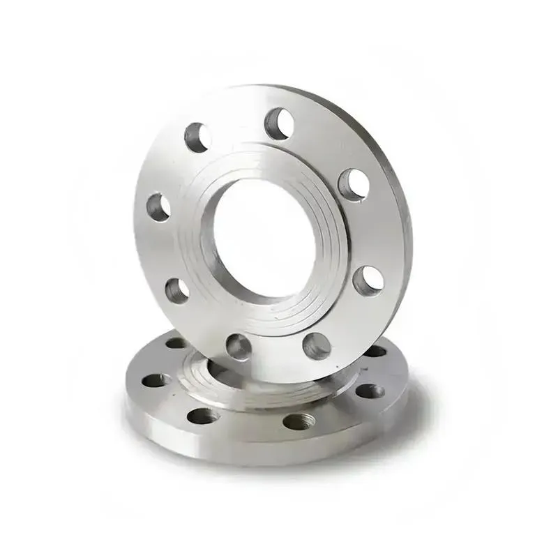
A flange—also referred to as a flange plate or rim—is a component used to connect shafts to one another, or, more commonly, to join the ends of pipes. Flanges are also utilized at the inlet and outlet ports of equipment to facilitate connections between two devices—for instance, the flange on a speed reducer. A "flange connection" or "flanged joint" refers to a detachable joint assembly comprising three interconnected elements—a flange, a gasket, and bolts—that together form a sealed structural unit. In the context of piping systems, a "pipe flange" specifically denotes a flange used for plumbing within the installation; when applied to equipment, it refers to the inlet or outlet flange of that specific device. Flanges feature a series of holes through which bolts are inserted to securely fasten the two flanges together, while a gasket placed between the flanges ensures a leak-proof seal. Flanges are broadly categorized into three types: threaded (screw-in) flanges, welded flanges, and clamp-type flanges. Flanges are invariably used in pairs; threaded flanges are suitable for low-pressure piping applications, whereas welded flanges are required for systems operating at pressures exceeding 4 kilograms per square centimeter. A sealing gasket is inserted between the two flange plates, which are then firmly secured using bolts. The thickness of a flange—as well as the specifications of the bolts used to fasten it—vary depending on the specific pressure rating required for the application. When connecting equipment such as water pumps or valves to piping systems, the corresponding connection points on these devices are often manufactured in the shape of a matching flange; this method of attachment is also referred to as a "flange connection." Generally, any connecting component that utilizes bolts to join and seal the perimeters of two flat surfaces—such as the joints in ventilation ducts—is termed a "flange"; such components may collectively be classified as "flange-type parts." However, since such a connection often constitutes merely a *portion* of a larger device—for instance, the interface between a flange and a water pump—it would be inappropriate to classify the entire water pump itself as a "flange-type part." Conversely, smaller components—such as valves—that feature such flanged interfaces may indeed be appropriately categorized as "flange-type parts."
-:-
For detailed product information, please contact sales.
-:
3D Systems LaserForm® Maraging Steel Flange (B), AFTER STRESS RELIEF Product Information
-:-
For detailed product information, please contact sales.
-:
3D Systems LaserForm® Maraging Steel Flange (B), AFTER STRESS RELIEF Synonyms
-:-
For detailed product information, please contact sales.
-:
3D Systems LaserForm® Maraging Steel (B), AFTER STRESS RELIEF Product Information
-:-
For detailed product information, please contact sales.
-:
# **3D Systems LaserForm® Maraging Steel (B), AFTER STRESS RELIEF**
## **Product Overview**
**3D Systems LaserForm® Maraging Steel (B), AFTER STRESS RELIEF** is a premium-grade, low-carbon, iron-nickel martensitic steel engineered for Direct Metal Printing (DMP) technology, processed through a **mandatory stress relief heat treatment** following the additive manufacturing process. This critical post-processing step transforms the as-built material state by significantly reducing residual stresses (typically by 80-90%), improving dimensional stability, and slightly enhancing ductility and toughness—all while maintaining the high strength characteristic of maraging steels. The material is supplied in this optimized stress-relieved condition, ready for precision machining, further aging treatments, or direct service in demanding applications where dimensional accuracy and stress-corrosion resistance are paramount.
---
## **TECHNICAL SPECIFICATIONS**
### **Manufacturing & Processing Specification**
| Parameter | Specification |
|-----------|---------------|
| **Primary Process** | Direct Metal Printing (DMP) / Laser Powder Bed Fusion (LPBF) |
| **Post-Process Condition** | **After Stress Relief** (mandatory treatment) |
| **Stress Relief Protocol** | 480°C ± 10°C for 2-4 hours, furnace cooled |
| **Optional Further Treatments** | Aging (H900 equivalent), Hot Isostatic Pressing (HIP) |
| **Compatible Systems** | 3D Systems ProX DMP 200/300, DMP Factory 350/500/850 |
| **Build Volume** | Up to 500 × 500 × 500 mm (system dependent) |
| **Optimal Layer Thickness** | 30-40 μm (for optimal stress relief response) |
| **Atmosphere Control** | High-purity argon (< 30 ppm O₂) during build |
| **Stress Relief Atmosphere** | Inert (Argon) or vacuum (< 10⁻² mbar) |
| **Build Plate Temperature** | 80-120°C |
### **Material Composition (wt%, Powder Specification)**
| Element | Target Range | Metallurgical Function After Stress Relief |
|---------|--------------|-----------------------------------|
| **Nickel (Ni)** | 17.0-19.0 | Martensite matrix formation, solid solution strengthening |
| **Cobalt (Co)** | 8.0-9.5 | Reduces martensite Ms temperature, enables precipitation |
| **Molybdenum (Mo)** | 4.5-5.5 | Primary precipitation-hardening element (precipitation initiated during stress relief) |
| **Titanium (Ti)** | 0.6-1.0 | Secondary precipitation hardening, grain refinement |
| **Aluminum (Al)** | 0.05-0.15 | Deoxidizer, contributes to precipitation hardening |
| **Carbon (C)** | ≤ 0.012 | **Ultra-low for maximum toughness and stress relief response** |
| **Manganese (Mn)** | ≤ 0.08 | Impurity control |
| **Silicon (Si)** | ≤ 0.08 | Impurity control |
| **Chromium (Cr)** | ≤ 0.20 | Impurity control (intentionally minimized for corrosion applications) |
| **Copper (Cu)** | ≤ 0.08 | Impurity control |
| **Phosphorus (P)** | ≤ 0.006 | Impurity control (enhanced purity) |
| **Sulfur (S)** | ≤ 0.004 | Impurity control (enhanced purity) |
| **Boron (B)** | 0.001-0.003 | Controlled addition for hardenability and grain boundary strengthening |
| **Iron (Fe)** | Balance | Matrix |
*Proprietary chemistry optimized for controlled stress relief response with minimal overaging*
---
## **MECHANICAL PROPERTIES (After Stress Relief)**
### **Tensile Properties (ASTM E8/E8M, Room Temperature)**
| Orientation | Ultimate Tensile Strength | Yield Strength (0.2%) | Elongation | Reduction of Area |
|-------------|---------------------------|-----------------------|------------|-------------------|
| **Horizontal (XY)** | 1100-1200 MPa | 1000-1100 MPa | 10-14% | 40-50% |
| **Vertical (Z)** | 1050-1150 MPa | 950-1050 MPa | 9-13% | 35-45% |
| **45° Diagonal** | 1075-1175 MPa | 975-1075 MPa | 9.5-13.5% | 37-47% |
*Note: Typical improvement of 2-4% elongation compared to as-built condition*
### **Comprehensive Mechanical Properties**
| Property | After Stress Relief | Test Standard | Notes |
|----------|---------------------|---------------|-------|
| **Hardness** | 36-40 HRC (Typical 38 HRC) | ASTM E18 | Uniform throughout part |
| **Impact Toughness** | 25-35 J | ASTM E23 | Charpy V-notch, 22°C (20-30% improvement vs as-built) |
| **Fatigue Strength** | 475-525 MPa | ASTM E466 | R = -1, 10⁷ cycles |
| **Young's Modulus** | 188-195 GPa | ASTM E111 | |
| **Shear Strength** | 700-800 MPa | ASTM B831 | |
| **Compressive Strength** | 1350-1500 MPa | ASTM E9 | |
| **Bearing Strength** | 1750-1950 MPa | ASTM E238 | |
| **Fracture Toughness (KIC)** | 70-90 MPa√m | ASTM E399 | CT specimens (improved vs as-built) |
| **Fatigue Crack Growth Rate** | da/dN = 2-4×10⁻⁸ m/cycle (ΔK=20 MPa√m) | ASTM E647 | Improved resistance |
| **Residual Stress** | < 50 MPa (surface), < 30 MPa (core) | X-ray diffraction | 80-90% reduction from as-built |
### **Anisotropy After Stress Relief**
- **Tensile Strength Anisotropy:** < 7% between orientations
- **Yield Strength Anisotropy:** < 8% between orientations
- **Ductility Anisotropy:** < 20% between orientations
- **Property Uniformity:** Improved throughout cross-section
---
## **STRESS RELIEF PROTOCOL & MICROSTRUCTURAL EVOLUTION**
### **Standard Stress Relief Thermal Cycle**
| Parameter | Specification | Metallurgical Effect |
|-----------|---------------|----------------------|
| **Heating Rate** | ≤ 100°C/hour to 300°C, then ≤ 50°C/hour to soak temperature | Minimizes thermal gradients |
| **Stress Relief Temperature** | 480°C ± 10°C (896°F ± 18°F) | Optimal for stress relaxation without significant overaging |
| **Hold Time** | 2 hours minimum, plus 1 hour per 25 mm thickness | Complete stress relaxation |
| **Atmosphere** | Inert (Argon) or vacuum (< 10⁻² mbar) | Precludes oxidation |
| **Cooling Rate** | Controlled furnace cooling at 30-50°C/hour to 200°C | Maintains low residual stress |
| **Final Cooling** | Air cool from 200°C to room temperature | |
### **Microstructural Transformation During Stress Relief**
| Microstructural Feature | As-Built Condition | After Stress Relief | Metallurgical Significance |
|------------------------|-------------------|---------------------|---------------------------|
| **Residual Stress Level** | High (200-400 MPa) | Low (< 50 MPa) | Dimensional stability, reduced distortion |
| **Dislocation Density** | Very high (10¹⁴-10¹⁵ m⁻²) | Moderate (10¹²-10¹³ m⁻²) | Improved ductility, reduced brittleness |
| **Precipitate State** | Incipient nano-precipitates | Coarsened precipitates (5-15 nm) | Early-stage aging effect |
| **Lath Martensite Structure** | Highly strained | Partially recovered | Improved toughness |
| **Prior Austenite Grain Boundaries** | Stressed, potentially embrittled | Relaxed, cleaner | Reduced intergranular failure risk |
| **Retained Austenite** | 1-3% | 2-4% (slight increase) | Minor ductility improvement |
### **Dimensional Stability Characteristics**
- **Typical Dimensional Change:** < 0.05% (shrinkage)
- **Distortion Reduction:** 70-85% compared to as-built
- **Flatness/Straightness Improvement:** Significant for thin-walled structures
- **Machining Response:** Predictable, minimal distortion during subsequent machining
---
## **PHYSICAL PROPERTIES (After Stress Relief)**
| Property | Value | Conditions/Notes |
|----------|-------|------------------|
| **Density** | 8.12-8.18 g/cm³ | > 99.6% dense per ASTM B962 |
| **Thermal Conductivity** | 20.5 W/m·K | 20°C |
| **Coefficient of Thermal Expansion** | 10.3 × 10⁻⁶/K | 20-200°C |
| **Specific Heat Capacity** | 465 J/kg·K | 20°C |
| **Electrical Resistivity** | 0.72 μΩ·m | 20°C |
| **Magnetic Permeability** | Ferromagnetic | Martensitic structure maintained |
| **Melting Range** | 1410-1450°C | Solidus-Liquidus |
| **Thermal Diffusivity** | 5.4 × 10⁻⁶ m²/s | 20°C |
---
## **FURTHER HEAT TREATMENT OPTIONS**
### **Subsequent Aging Treatment (Optional)**
- **Standard Aging:** 480°C ± 5°C for 3-6 hours
- **Resulting Properties:** UTS 1900-2000 MPa, YS 1800-1900 MPa, 6-9% elongation
- **Hardness:** 49-53 HRC
- **Note:** Direct aging from stress-relieved condition possible, though solution treatment (820°C) followed by aging yields optimal properties
### **Hot Isostatic Pressing (HIP) Integration**
- **Combined Process:** HIP (1150°C/100 MPa/2-4 hours) followed by stress relief
- **Benefits:** Porosity elimination (< 0.01%) + stress relief in one cycle
- **Resulting Properties:** Enhanced fatigue and fracture toughness
### **Stress Relief Only vs. Full Aging**
| Property | Stress Relief Only | Stress Relief + Full Aging |
|----------|-------------------|----------------------------|
| **Primary Use** | Machining stability, dimensional accuracy | Maximum strength applications |
| **Hardness (HRC)** | 36-40 | 49-53 |
| **Machinability** | Excellent | More difficult |
| **Dimensional Change** | Minimal (< 0.05%) | Significant (0.1-0.2%) |
| **Lead Time** | Shorter (2-4 hours) | Longer (6-10 hours including solution) |
---
## **DESIGN FOR ADDITIVE MANUFACTURING & STRESS RELIEF**
### **Geometric Guidelines for Stress-Relieved Parts**
| Parameter | Recommendation | Rationale |
|-----------|----------------|-----------|
| **Minimum Wall Thickness** | 0.8 mm (unsupported), 0.6 mm (supported) | Ensures dimensional stability during stress relief |
| **Maximum Section Thickness** | 150 mm (standard furnace), 300 mm (specialized) | Stress relief effectiveness diminishes with thickness |
| **Section Transitions** | Gradual (3:1 ratio maximum) | Prevents stress concentration during thermal cycling |
| **Internal Cavities** | Minimum 4 mm access ports | Allows stress relief atmosphere penetration |
| **Feature Size** | Minimum 0.4 mm (post-stress relief) | Accounts for potential slight dimensional changes |
| **Support Contact Areas** | Designed for easy removal post-stress relief | Stressed parts may be more difficult to separate |
| **Flatness Critical Features** | Stress relieve before final machining | Allows for distortion correction |
### **Stress Relief-Specific Design Considerations**
1. **Thermal Mass Distribution:** Uniform wall thicknesses promote even stress relief
2. **Constraint During Stress Relief:** Design fixturing/anchoring points if dimensional stability is critical
3. **Residual Stress Management:** Avoid sharp corners (minimum R2.0 mm)
4. **Support Strategy:** Consider stress relief distortion when planning support locations
5. **Tolerance Allocation:** Include ±0.1% dimensional allowance for stress relief
---
## **PRIMARY APPLICATIONS**
### **Precision Tooling & Molding**
- **Injection Mold Inserts:** Cores, cavities requiring dimensional stability for close-tolerance molding
- **Die Casting Tooling:** Cores, ejector pins, slides for aluminum/magnesium casting
- **Stamping & Forming Dies:** Progressive dies, forming punches requiring accuracy
- **Extrusion Dies:** For non-ferrous metals requiring precise profiles
- **Glass Molding Tools:** Preforms, gob guides requiring thermal stability
### **Aerospace & Defense**
- **Flight Critical Components:** Brackets, mounts, fittings requiring certified dimensional stability
- **Tooling for Composites:** Caul plates, molds for carbon fiber components
- **Ground Support Equipment:** Precision alignment fixtures, assembly tools
- **Satellite Components:** Structural elements requiring stable dimensions in thermal cycles
- **Wind Tunnel Models:** Precision aerodynamic surfaces
### **Automotive & Motorsports**
- **Production Tooling:** Dies, molds for high-volume components
- **Prototype Tooling:** For pre-production validation
- **Race Car Components:** Suspension parts, mounting brackets requiring precision
- **Test & Validation Equipment:** Durability test fixtures, measurement apparatus
### **Industrial & Manufacturing**
- **Machine Tool Components:** Spindles, slides, brackets for precision equipment
- **Gauges & Measurement Tools:** Calibration standards, reference surfaces
- **Robotics & Automation:** End-effectors, grippers, positioning stages
- **Material Handling:** Precision guides, rails, bearing surfaces
### **Medical & Dental (Non-Implant)**
- **Surgical Instrument Components:** Precision mechanical parts, joint components
- **Dental Tooling:** Crown/bridge fabrication equipment, orthodontic appliance tools
- **Medical Device Components:** Housings, mechanisms requiring dimensional stability
- **Laboratory Equipment:** Precision fixtures, alignment tools
### **Energy & Heavy Industry**
- **Turbomachinery Components:** Casings, brackets, supports
- **Oil & Gas Tooling:** Downhole tool components, measurement fixtures
- **Power Generation:** Turbine components, alignment fixtures
- **Nuclear:** Non-active tooling, handling equipment
---
## **POST-PROCESSING & FINISHING (After Stress Relief)**
### **Machining Considerations**
- **Tool Material:** Carbide (K10-K20) or CBN for best results
- **Cutting Speed:** 40-60 m/min (turning)
- **Feed Rate:** 0.15-0.30 mm/rev
- **Depth of Cut:** 1.0-3.0 mm (light to moderate)
- **Coolant:** Essential for heat dissipation and dimensional control
- **Chip Formation:** Short, broken chips – good machinability
- **Dimensional Stability:** Excellent – minimal distortion during machining
### **Surface Enhancement Treatments**
- **Grinding:** Achieves Ra < 0.4 μm with proper wheels and technique
- **Polishing:** Mirror finish (Ra < 0.05 μm) achievable with progressive steps
- **Electropolishing:** Limited effectiveness due to low Cr content
- **Shot Peening:** Almen 0.006-0.010A for fatigue improvement
- **Coating Application:** Excellent substrate for TiN, TiCN, DLC coatings
- **Passivation:** Not typically required (low Cr content)
### **Joining Technologies**
- **Welding:** Possible with proper procedure (PWHT recommended)
- **Adhesive Bonding:** Good with proper surface preparation
- **Mechanical Fastening:** Standard practices applicable
- **Brazing:** Suitable with nickel-based brazing alloys
---
## **QUALITY STANDARDS & CERTIFICATIONS**
| Standard | Applicability | Compliance Status |
|----------|---------------|-------------------|
| **ASTM F3605** | Maraging Steel for Additive Manufacturing | Chemistry and properties compliant |
| **AMS 6514** | Maraging Steel, 18Ni (200 Grade) | Similar grade properties |
| **ASTM A538** | Precipitation Hardening Steel | Property equivalent |
| **ISO/ASTM 52904** | Additive Manufacturing - Process Characteristics | Compliant |
| **ISO 9001:2015** | Quality Management System | Certified |
| **AS9100** | Aerospace Quality Management | Compliant |
| **NADCAP** | Heat Treating Accreditation | Available through certified partners |
### **Testing & Documentation Package**
- **Full Chemical Analysis:** ICP-OES, combustion analysis for C/S/N
- **Mechanical Testing:** Tensile (multiple orientations), hardness, impact
- **Residual Stress Measurement:** X-ray diffraction or hole-drilling method
- **Microstructural Analysis:** Grain size, phase identification, porosity assessment
- **Non-Destructive Testing:** Dye penetrant, X-ray radiography available
- **Certification:** 3.1 Material Certificate per EN 10204 with stress relief parameters
---
## **COMPARATIVE PERFORMANCE DATA**
| Condition | UTS (MPa) | YS (MPa) | Elongation (%) | Impact (J) | Primary Application |
|-----------|-----------|----------|----------------|------------|---------------------|
| **As-Built** | 1150-1250 | 1050-1150 | 8-12 | 20-30 | Rapid prototypes, non-critical tools |
| **After Stress Relief** | 1100-1200 | 1000-1100 | 10-14 | 25-35 | Precision tooling, dimensional-critical parts |
| **Stress Relief + Aged** | 1900-2000 | 1800-1900 | 6-9 | 15-25 | Maximum strength applications |
| **Wrought & Aged** | 2000-2100 | 1900-2000 | 5-8 | 10-20 | Traditional high-strength applications |
---
## **STORAGE & HANDLING**
### **Powder Management**
- **Storage Life:** 18 months in original argon-purged packaging
- **Storage Conditions:** < 40% relative humidity, 15-30°C
- **Handling:** Inert atmosphere glove box recommended for extended exposure
- **Safety:** NFPA 484 combustible metals standard compliance
### **Stress Relief Facility Requirements**
- **Furnace Type:** Vacuum or atmosphere-controlled with recording capability
- **Temperature Uniformity:** ±8°C throughout work zone
- **Heating Elements:** Nickel-chromium or molybdenum
- **Atmosphere Control:** Capable of < 10⁻² mbar vacuum or argon purging
- **Cooling Control:** Programmable cooling rate capability
- **Certification:** NADCAP heat treating accreditation preferred for aerospace
---
## **TECHNICAL SUPPORT SERVICES**
- **Stress Relief Protocol Development:** Custom cycles for specific geometries
- **Distortion Prediction & Compensation:** FEA analysis services
- **Application Engineering:** Material selection and design optimization
- **Failure Analysis:** Comprehensive metallurgical investigation
- **Quality Assurance:** Development of inspection and testing protocols
---
## **ORDERING INFORMATION**
| Item | Specification |
|------|---------------|
| **Standard Packaging** | 5 kg, 10 kg, 20 kg argon-sealed containers |
| **Stress Relief Service** | Available as standard or optional service |
| **Lead Time** | 3-8 weeks (depending on quantity and testing) |
| **Documentation** | Certificate of Analysis, MSDS, Stress Relief Certificate |
| **Custom Processing** | Available for specialized requirements |
---
**3D Systems Corporation**
*Precision Engineered Additive Manufacturing Solutions*
[www.3dsystems.com](https://www.3dsystems.com)
Phone: +1-803-326-3900
Email: materials@3dsystems.com
---
**CRITICAL PROCESS NOTE:**
Parts manufactured with LaserForm® Maraging Steel (B) material intended for AFTER STRESS RELIEF condition **MUST** undergo the specified stress relief heat treatment before being placed in service or subjected to significant machining operations. This treatment is essential for achieving the specified dimensional stability and mechanical properties.
**DISCLAIMER:**
The data provided represents typical values obtained from standardized test specimens manufactured under controlled conditions. Actual performance in production applications may vary based on specific geometry, build parameters, stress relief execution, and service conditions. For critical applications, comprehensive application-specific testing is mandatory. Specifications are subject to change without notice. Always consult the most current technical data sheets before design and production.
© 2024 3D Systems Corporation. All rights reserved. LaserForm is a registered trademark of 3D Systems Corporation.
-:-
For detailed product information, please contact sales.
-:
3D Systems LaserForm® Maraging Steel (B), AFTER STRESS RELIEF Specification
Dimensions
Size:
Diameter 20-1000 mm Length <7225 mm
Size:We can customized as required
Standard:
Per your request or drawing
We can customized as required
Properties(Theoretical)
Chemical Composition
-:-
For detailed product information, please contact sales.
-:
3D Systems LaserForm® Maraging Steel (B), AFTER STRESS RELIEF Properties
-:-
For detailed product information, please contact sales.
-:
Applications of 3D Systems LaserForm® Maraging Steel Flange (B), AFTER STRESS RELIEF
-:-
For detailed product information, please contact sales.
-:
Chemical Identifiers 3D Systems LaserForm® Maraging Steel Flange (B), AFTER STRESS RELIEF
-:-
For detailed product information, please contact sales.
-:
Packing of 3D Systems LaserForm® Maraging Steel Flange (B), AFTER STRESS RELIEF
-:-
For detailed product information, please contact sales.
-:
Standard Packing:
-:-
For detailed product information, please contact sales.
-:
Typical bulk packaging includes palletized plastic 5 gallon/25 kg. pails, fiber and Steel Flange drums to 1 ton super sacks in full container (FCL) or truck load (T/L) quantities. Research and sample quantities and hygroscopic, oxidizing or other air sensitive materials may be packaged under argon or vacuum. Solutions are packaged in polypropylene, plastic or glass jars up to palletized 3696 gallon liquid totes Special package is available on request. E FORUs’ is carefully handled to minimize damage during storage and transportation and to preserve the quality of our products in their original condition