1,We Manufacturing processes are primarily classified into four types:
1:Forging,
2:Casting,
3:Cutting,
4:Rolling.
2,We can manufacture in accordance with these standards.
Standards:
GB Series (Chinese Standards), JB Series (Machinery Standards), HG Series (Chemical Industry Standards), ASME B16.5 (American Standards), BS4504 (British Standards), DIN (German Standards), and JIS (Japanese Standards).
Internationally, there are two primary systems of pipe flange standards: the European system, represented by the German DIN standards (including those of the former Soviet Union), and the American system, represented by the US ANSI pipe flange standards. Other common standards include: the Chinese Ministry of Machinery Industry standards (JB series), the Ministry of Chemical Industry standards (HG series), the Chinese National Standard *GB/T 9112–9124-2010 Steel Pipe Flanges*, as well as US standards (ASME B16.5), British standards (BS4504), German standards (DIN), Japanese standards (JIS), and marine standards (CBM), among others.
The nominal pressure ratings for the PN series are designated by "PN" and comprise the following nine levels: PN2.5, PN6, PN10, PN16, PN25, PN40, PN63, PN100, and PN160.
The nominal pressure ratings for the Class series are designated by "Class" and comprise the following six levels: Class150, Class300, Class600, Class900, Class1500, and Class2500.
Flange Classification
1. **According to Chemical Industry Standards:** Flanges are classified as follows:
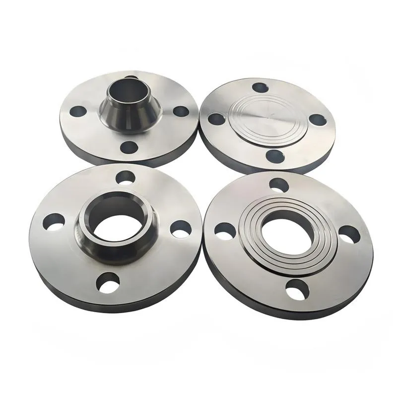
Plate Flat Welding Flange (PL), Necked Flat Welding Flange (SO), Necked Butt Welding Flange (WN), Integral Flange (IF), Socket Welding Flange (SW), Threaded Flange (Th), Butt Welding Ring Loose Flange (PJ/SE), Blind Flange (BL), Flat Welding Ring Loose Flange (PJ/PJ), and Lined Blind Flange (BL(s)).
2. **According to Petrochemical (SH) Industry Standards:** Flanges are classified as follows:
Threaded Flange (PL), Butt Welding Flange (WN), Flat Welding Flange (SO), Socket Welding Flange (SW), Loose Flange (LJ), and Blind Flange (no specific designation).
3. **According to Machinery (JB) Industry Standards:** Flanges are classified as follows:
Integral Flange, Butt Welding Flange, Plate Flat Welding Flange, Butt Welding Ring Plate Loose Flange, Flat Welding Ring Plate Loose Flange, Lap Joint Ring Plate Loose Flange, and Blind Flange.
4. **According to Connection Method/Type:** Flanges are classified as follows:
Plate Flat Welding Flange, Necked Flat Welding Flange, Necked Butt Welding Flange, Socket Welding Flange, Threaded Flange, Blind Flange, Necked Butt Welding Ring Loose Flange, Flat Welding Ring Loose Flange, Ring-Type Joint (RTJ) Flange and Blind Flange, Large-Diameter Plate Flange, Large-Diameter High-Neck Flange, Figure-8 Blind Plate, Butt Welding Ring Loose Flange, etc.
5. **According to the Component Being Connected:** Flanges can be classified into Vessel Flanges and Pipe Flanges.
6. **According to Structural Type:** Flanges include Integral Flanges, Threaded Flanges, Flat Welding Flanges, Butt Welding Flanges, Lap Joint (Loose/Swivel) Flanges, and Blind Flanges.
A flange—also referred to as a flange plate or rim—is a component used to connect shafts to one another, or, more commonly, to join the ends of pipes. Flanges are also utilized at the inlet and outlet ports of equipment to facilitate connections between two devices—for instance, the flange on a speed reducer. A "flange connection" or "flanged joint" refers to a detachable joint assembly comprising three interconnected elements—a flange, a gasket, and bolts—that together form a sealed structural unit. In the context of piping systems, a "pipe flange" specifically denotes a flange used for plumbing within the installation; when applied to equipment, it refers to the inlet or outlet flange of that specific device. Flanges feature a series of holes through which bolts are inserted to securely fasten the two flanges together, while a gasket placed between the flanges ensures a leak-proof seal. Flanges are broadly categorized into three types: threaded (screw-in) flanges, welded flanges, and clamp-type flanges. Flanges are invariably used in pairs; threaded flanges are suitable for low-pressure piping applications, whereas welded flanges are required for systems operating at pressures exceeding 4 kilograms per square centimeter. A sealing gasket is inserted between the two flange plates, which are then firmly secured using bolts. The thickness of a flange—as well as the specifications of the bolts used to fasten it—vary depending on the specific pressure rating required for the application. When connecting equipment such as water pumps or valves to piping systems, the corresponding connection points on these devices are often manufactured in the shape of a matching flange; this method of attachment is also referred to as a "flange connection." Generally, any connecting component that utilizes bolts to join and seal the perimeters of two flat surfaces—such as the joints in ventilation ducts—is termed a "flange"; such components may collectively be classified as "flange-type parts." However, since such a connection often constitutes merely a *portion* of a larger device—for instance, the interface between a flange and a water pump—it would be inappropriate to classify the entire water pump itself as a "flange-type part." Conversely, smaller components—such as valves—that feature such flanged interfaces may indeed be appropriately categorized as "flange-type parts."
-:-
For detailed product information, please contact sales.
-:
Malleable Iron Flange casting, Class M7002 liquid quenched and tempered Product Information
-:-
For detailed product information, please contact sales.
-:
Malleable Iron Flange casting, Class M7002 liquid quenched and tempered Synonyms
-:-
For detailed product information, please contact sales.
-:
Malleable iron casting, Class M7002 liquid quenched and tempered Product Information
-:-
For detailed product information, please contact sales.
-:
# **Malleable Iron Casting - Class M7002 Liquid Quenched & Tempered**
## **1. Executive Summary**
**Class M7002 Liquid Quenched & Tempered** represents the **ultimate performance tier** in commercially available quenched and tempered malleable iron technology, achieving exceptional **minimum tensile strength of 700 MPa (101,500 psi)** with **2% minimum elongation**. This premium grade combines advanced alloy metallurgy with precisely controlled liquid quenching (typically oil or fast polymer) and sophisticated tempering processes to deliver mechanical properties that directly compete with heat-treated alloy steels. Designed for extreme-duty applications where conventional cast irons fail, M7002 offers a unique value proposition: **steel-like strength with cast iron's manufacturing advantages**, including complex geometry capability, excellent damping characteristics, and cost-effective production of intricate components.
## **2. International Standards & Specifications**
### **Primary Standards Reference**
- **ASTM A220/A220M**: *Standard Specification for Pearlitic Malleable Iron Castings* (Performance baseline)
- **ASTM A602**: *Automotive Malleable Iron Castings* (Common application specification)
- **ISO 5922**: *Malleable cast irons - Classification* (International reference)
### **International Grade Equivalents**
| **Standard** | **Designation** | **Region** | **Notes** |
|--------------|-----------------|------------|-----------|
| **ISO 5922** | **JMB 700-2** | International | Direct performance equivalent |
| **EN 1562** | EN-GJMB-700-2 | European Union | European standard equivalent |
| **JIS G 5705** | FCMB 700 | Japan | Japanese industrial standard |
| **GB/T 9440** | JMB 700 | China | Chinese national standard |
| **Custom OEM Specs** | Varies by manufacturer | Global | Often specified under proprietary codes |
### **Process-Specific Designation**
The **"Liquid Quenched & Tempered"** specification is critical and indicates:
- **Quenching Medium**: Oil, polymer, or specialized quenchants
- **Cooling Rate**: Typically 20-80°C/second surface cooling
- **Process Control**: Precise temperature and agitation control
- **Tempering Protocol**: Multiple-stage tempering for optimal properties
## **3. Chemical Composition**
### **Advanced Alloy System Design**
Class M7002 employs a sophisticated multi-alloy approach to achieve maximum hardenability while maintaining process stability:
| **Element** | **Target Range (%)** | **Metallurgical Function** | **Critical Impact** |
|-------------|---------------------|---------------------------|-------------------|
| **Carbon (C)** | 2.60-2.95 | Primary strength foundation, carbide formation | Directly controls maximum hardness potential |
| **Silicon (Si)** | 1.80-2.40 | Graphitization control, solid solution strengthening | Enhances hardenability and strength |
| **Manganese (Mn)** | **1.20-1.80** | **Primary hardenability agent** | Determines depth of hardening in sections |
| **Chromium (Cr)** | **0.40-0.80** | **Secondary hardening, wear resistance** | Forms stable carbides, refines microstructure |
| **Molybdenum (Mo)** | **0.25-0.50** | **Heavy section capability** | Prevents temper embrittlement, enhances high-temp strength |
| **Nickel (Ni)** | 0.30-0.70 | Toughness enhancement | Improves impact resistance at high strength levels |
| **Vanadium (V)** | 0.10-0.25 | Grain refinement, secondary hardening | Controls prior austenite grain size |
| **Copper (Cu)** | 0.50-1.00 | Hardenability aid, corrosion resistance | Broadens processing window |
| **Boron (B)** | 0.001-0.005 | Potent hardenability enhancer | Multiplies effectiveness of other alloys |
| **Phosphorus (P)** | ≤ 0.05 | Strictly controlled impurity | Minimized for toughness preservation |
| **Sulfur (S)** | ≤ 0.05 | Strictly controlled impurity | Minimized for ductility and machinability |
### **Alloy Design Philosophy**
- **Total Alloy Content**: Σ(Mn+Cr+Mo+Ni+Cu) ≥ 3.0%
- **Carbon Equivalent**: 4.0-4.4% for optimal castability/hardenability balance
- **Hardenability Index**: DI (Ideal Diameter) ≥ 6 inches for oil quenching
- **Alloy Synergy**: Balanced ratios for maximum transformation hardening
- **Purity Requirements**: Oxygen ≤ 25 ppm, Nitrogen ≤ 60 ppm for consistent properties
## **4. Physical & Mechanical Properties**
### **Minimum Performance Requirements**
| **Property** | **Minimum Value** | **Typical Achieved Range** | **Test Standard** |
|--------------|------------------|---------------------------|------------------|
| **Tensile Strength** | 700 MPa (101,500 psi) | 700-850 MPa | ASTM E8 |
| **Yield Strength (0.2%)** | 480 MPa (69,600 psi) | 480-600 MPa | ASTM E8 |
| **Elongation** | 2% in 50 mm | 2-4% | ASTM E8 |
| **Reduction of Area** | 8% minimum | 8-15% | ASTM E8 |
| **Brinell Hardness** | 285-352 HB | 302-341 HB | ASTM E10 |
### **Comprehensive Property Profile**
#### **Mechanical Characteristics**
- **Tensile Strength**: 700-850 MPa (101,500-123,250 psi)
- **Yield Strength**: 480-600 MPa (69,600-87,000 psi)
- **Yield Ratio**: 0.69-0.71
- **Elongation**: 2-4% (typically 2.5-3.5%)
- **Shear Strength**: 450-550 MPa
- **Compressive Strength**: 800-950 MPa
- **Modulus of Elasticity**: 185-195 GPa (26.8-28.3 × 10⁶ psi)
- **Poisson's Ratio**: 0.27-0.29
- **Shear Modulus**: 72-77 GPa
#### **Hardness & Wear Performance**
- **Brinell Hardness**: 285-352 HB (typically 302-341 HB)
- **Rockwell Hardness**: 30-38 HRC equivalent
- **Vickers Hardness**: 305-370 HV
- **Abrasion Resistance**: Excellent - 5-6× better than ferritic grades
- **Scuffing Resistance**: Superior with proper surface finish
- **Surface Hardening Potential**: 55-60 HRC achievable with induction hardening
#### **Fatigue & Fracture Properties**
- **Fatigue Limit (10⁷ cycles)**: 280-350 MPa (rotating bending)
- **Fatigue Ratio**: 0.40-0.45
- **Endurance Limit**: 0.38-0.42 of tensile strength
- **Charpy V-Notch Impact**: 6-12 J at 20°C
- **Fracture Toughness (K₁c)**: 35-50 MPa√m
- **Crack Growth Threshold**: ΔK_th = 6-8 MPa√m
- **Paris Law Exponent**: n = 2.9-3.3
- **Transition Temperature**: 10-30°C ductile-to-brittle transition
#### **Physical & Thermal Properties**
- **Density**: 7.32-7.42 g/cm³
- **Melting Range**: 1160-1230°C
- **Thermal Conductivity**: 34-40 W/m·K at 20°C
- **Specific Heat**: 450-480 J/kg·K
- **Thermal Expansion**: 10.2-11.0 × 10⁻⁶/°C (20-200°C)
- **Electrical Resistivity**: 0.40-0.48 μΩ·m
- **Damping Capacity**: 3-5× better than equivalent steels
- **Magnetic Properties**: Strongly ferromagnetic
## **5. Liquid Quenching & Tempering Process**
### **Advanced Four-Stage Heat Treatment**
**Stage 1: Precision Graphitization**
- **Temperature**: 930-960°C
- **Time**: 6-15 hours with programmed cycles
- **Atmosphere**: Neutral with dew point -15 to -25°C
- **Control**: Real-time carbon activity monitoring
- **Result**: Complete carbide decomposition with minimal grain growth
**Stage 2: High-Temperature Austenitization**
- **Heating Rate**: Controlled to prevent thermal shock
- **Austenitizing Temperature**: 870-900°C
- **Soaking Time**: 1.5-3.0 hours for full transformation
- **Carbon Potential**: 0.9-1.1% to prevent decarburization
- **Grain Size Control**: ASTM 8-10 achieved
**Stage 3: Intensive Liquid Quenching**
- **Quenching Medium**: Fast oil or high-performance polymer
- **Cooling Rate**: 50-100°C/second at surface
- **Agitation**: High-velocity, uniform flow patterns
- **Temperature Control**: Quenchant maintained at 40-70°C
- **Result**: Predominantly martensitic transformation with minimal retained austenite
**Stage 4: Multiple-Temperature Tempering**
- **First Temper**: 200-250°C for 2 hours (stress relief)
- **Second Temper**: 450-550°C for 2-4 hours (toughness development)
- **Third Temper**: 300-350°C for 1-2 hours (stabilization)
- **Atmosphere**: Protective or air with controlled oxidation
- **Cooling**: Controlled to prevent temper embrittlement
### **Final Microstructural Characteristics**
- **Matrix**: Tempered martensite with fine carbides (90-95%)
- **Prior Austenite Grain Size**: ASTM 8-10 (≤ 0.022 mm)
- **Martensite Lath Width**: 0.2-1.0 μm
- **Temper Carbon Distribution**: Fine, uniform aggregates (15-40 μm)
- **Retained Austenite**: < 3% (typically 1-2%)
- **Carbide Size**: 0.05-0.20 μm, uniformly dispersed
- **Inclusion Rating**: ASTM E45 Method A, ≤ 1.5
- **Microcleanliness**: Oxygen ≤ 25 ppm, Nitrogen ≤ 60 ppm
## **6. Manufacturing Requirements**
### **Foundry Capabilities**
- **Melting**: Medium frequency induction furnace with precise chemistry control
- **Charge Materials**: High-purity pig iron, low-tramp element steel scrap
- **Inoculation**: Advanced late-stream inoculation with controlled fade
- **Temperature Control**: ±10°C pouring temperature tolerance
- **Molding**: Chemically bonded sand systems for dimensional accuracy
- **Quality Systems**: IATF 16949 or equivalent required
### **Machinability Characteristics**
- **Relative Machinability**: 50-65% of B1112 steel
- **Cutting Speeds**: 60-100 m/min with carbide tools
- **Feed Rates**: 0.10-0.20 mm/rev
- **Tool Recommendations**: PVD-coated carbide, ceramic, or CBN tools
- **Surface Finish**: 0.8-1.6 μm Ra achievable
- **Power Requirements**: 2-3× higher than conventional cast irons
### **Post-Processing Capabilities**
- **Heat Treatment Response**: Excellent for secondary hardening processes
- **Surface Treatments**: Responds well to nitriding, induction hardening
- **Joining Methods**: Limited weldability, excellent for mechanical joining
- **Coatings**: Accepts all common industrial coatings and platings
## **7. Product Applications**
### **Extreme-Duty Automotive**
- **High-Performance Powertrains**
- Turbocharged diesel crankshafts
- Racing engine components
- Heavy-duty transmission gears
- High-torque differential carriers
- **Commercial Vehicle Systems**
- Class 8 truck steering knuckles
- Heavy-duty wheel hubs
- Fifth wheel components
- Brake system anchors and calipers
### **Heavy Equipment & Machinery**
- **Construction Equipment**
- Excavator track components
- Bulldozer final drive gears
- Crane swing mechanisms
- Paving machine drives
- **Agricultural Machinery**
- Combine harvester final drives
- Tractor PTO shafts
- High-horsepower gearboxes
- Planting system drives
### **Industrial & Specialized Applications**
- **Energy Sector**
- Wind turbine gearbox components
- Oil drilling equipment
- Pump and compressor crankshafts
- High-pressure valve bodies
- **Material Handling**
- Heavy conveyor drives
- Crane hoist mechanisms
- Mining equipment gears
- Heavy lift equipment components
- **Defense & Aerospace Support**
- Military vehicle track components
- Support equipment gears
- Landing gear components for ground support
- Weapon system structural components
## **8. Design Engineering Guidelines**
### **Section Size Limitations**
- **Optimal Wall Thickness**: 6-25 mm
- **Maximum Uniform Section**: 40 mm
- **Minimum Practical Section**: 4 mm
- **Property Uniformity**: ±12% across design section
### **Stress Analysis Considerations**
- **Design Stress (Static)**: 175-225 MPa (25,400-32,600 psi)
- **Fatigue Design Limit**: 120-180 MPa (17,400-26,100 psi)
- **Safety Factors**: 3.0-3.5 for dynamic loading
- **Stress Concentrations**: Kt ≤ 2.0 recommended
### **Geometric Recommendations**
- **Fillet Radii**: Minimum 3 mm, preferred 5 mm
- **Section Transitions**: Gradual changes (< 30° angle)
- **Rib Design**: Height/width ratio ≤ 4:1
- **Boss Design**: Diameter ≤ 2× wall thickness
- **Hole Placement**: Minimum 1.5× diameter from edges
## **9. Quality Assurance & Testing**
### **Mandatory Testing Requirements**
1. **Chemical Analysis**: Each melt using optical emission spectroscopy
2. **Mechanical Testing**: Tensile tests from separately cast keel blocks
3. **Hardness Testing**: Multiple locations including surface and core
4. **Microstructural Examination**: 100% verification of proper structure
5. **Non-Destructive Testing**: UT, MT, or RT as specified by drawing
### **Advanced Testing (When Specified)**
- **Fatigue Testing**: Axial or rotating bending to 10⁷ cycles
- **Fracture Toughness**: ASTM E399 testing procedures
- **Residual Stress Analysis**: X-ray diffraction methods
- **Metallographic Analysis**: Quantitative image analysis at ≥500×
- **Wear Testing**: ASTM G65 or G77 standard tests
### **Certification Requirements**
- **Material Certificates**: EN 10204 3.1 or 3.2 Type
- **Traceability**: Full heat/lot traceability maintained
- **Process Records**: Complete heat treatment documentation
- **Statistical Process Control**: Cp ≥ 1.67, Cpk ≥ 1.33
- **First Article Inspection**: Comprehensive dimensional reports
## **10. Comparative Analysis**
### **Versus Lower Strength Malleable Irons**
| **Property** | **Class M7002 vs. M5503** | **Advantage** |
|--------------|--------------------------|---------------|
| **Tensile Strength** | +27% higher | Major |
| **Yield Strength** | +25% higher | Significant |
| **Hardness** | +15% higher | Moderate |
| **Wear Resistance** | 20-30% better | Major |
| **Fatigue Strength** | 15-20% higher | Important |
| **Machinability** | 20-25% lower | Trade-off |
### **Versus Competing Materials**
- **vs. Forged 4340 Steel**: 85-90% strength at 50-70% cost for complex parts
- **vs. Austempered Ductile Iron (Grade 4)**: Higher strength, different property profile
- **vs. Cast Steel (ASTM A148 Gr. 120-95)**: Better damping, similar strength, better castability
- **vs. Aluminum Alloys (A201.0-T7)**: Higher density, much higher strength, better high-temp performance
## **11. Economic & Technical Considerations**
### **Cost Factors**
- **Material Cost**: 40-60% higher than Class M5503
- **Processing Cost**: Significant due to complex heat treatment
- **Tooling Cost**: Similar to other high-performance cast irons
- **Life Cycle Cost**: Excellent for extreme wear applications
### **Technical Trade-offs**
- **Strength vs. Toughness**: Optimized for strength-dominant applications
- **Cost vs. Performance**: Premium material for premium applications
- **Manufacturability vs. Properties**: Requires advanced foundry capabilities
- **Weight vs. Strength**: Excellent strength-to-weight ratio
### **Supply Chain Considerations**
- **Limited Suppliers**: Specialized foundries required
- **Lead Times**: Longer due to complex processing
- **Technical Support**: Requires metallurgical expertise
- **Global Availability**: Limited to major industrial regions
## **12. Future Developments & Trends**
### **Technical Advancements**
1. **Alloy Optimization**: Computational materials design for improved toughness
2. **Process Innovation**: Reduced energy heat treatment cycles
3. **Quality Monitoring**: Real-time process control systems
4. **Surface Engineering**: Advanced coating integration
### **Market Trends**
- **Lightweighting**: Continued development for weight-sensitive applications
- **Electrification**: Adaptation for high-torque electric vehicle components
- **Digital Integration**: Industry 4.0 manufacturing implementation
- **Sustainability**: Reduced energy and improved recyclability
### **Research Directions**
- **Nanostructured Variants**: For ultra-high performance applications
- **Hybrid Materials**: Composite structures with other materials
- **Smart Castings**: Embedded sensors for condition monitoring
- **Advanced Simulation**: Digital twin technology for process optimization
## **13. Implementation Strategy**
### **Success Factors**
1. **Early Supplier Involvement**: Critical for design optimization
2. **Prototype Development**: Essential for process validation
3. **Comprehensive Testing**: Extensive validation before production
4. **Continuous Monitoring**: Statistical process control during production
### **Risk Mitigation**
- **Dual Sourcing**: Strategy where possible
- **Failure Mode Analysis**: Comprehensive FMEA
- **Conservative Design**: Adequate safety margins
- **Regular Audits**: Supplier assessment and verification
### **Development Process**
- **Phase 1**: Material suitability analysis (2-4 months)
- **Phase 2**: Process development and optimization (3-6 months)
- **Phase 3**: Prototype manufacturing and testing (2-4 months)
- **Phase 4**: Production qualification (2-3 months)
- **Phase 5**: Ramp-up and continuous improvement (ongoing)
## **14. Conclusion**
**Class M7002 Liquid Quenched & Tempered** represents the **ultimate achievement in commercial malleable iron technology**, delivering tensile strengths approaching 850 MPa while maintaining useful ductility. This premium engineering material fills a critical niche between standard cast irons and alloy steels, offering designers a unique combination of castability, strength, wear resistance, and damping capacity.
The successful application of Class M7002 requires sophisticated foundry and heat treatment capabilities, careful design consideration of its property limitations, and thorough quality assurance practices. When properly implemented, it provides exceptional value in applications where its specific property profile aligns with demanding performance requirements, particularly in heavy-duty automotive, construction, and industrial equipment sectors.
As manufacturing technologies continue to advance, Class M7002 is poised to evolve through material and process innovations, maintaining its position as a high-performance engineering solution for the most challenging mechanical applications. Its continued development reflects the ongoing relevance of advanced cast iron technology in modern engineering design.
### **Final Recommendation**
Class M7002 should be specified when:
1. **Strength Requirements** exceed conventional cast iron capabilities
2. **Component Complexity** favors casting over forging
3. **Cost-Effectiveness** is critical for complex geometries
4. **Damping Capacity** provides operational benefits
5. **Wear Resistance** is a primary design consideration
With proper design, manufacturing, and quality control, Class M7002 Liquid Quenched & Tempered delivers unmatched performance in its class, providing engineers with a powerful material solution for extreme-duty applications.
-:-
For detailed product information, please contact sales.
-:
Malleable iron casting, Class M7002 liquid quenched and tempered Specification
Dimensions
Size:
Diameter 20-1000 mm Length <6588 mm
Size:We can customized as required
Standard:
Per your request or drawing
We can customized as required
Properties(Theoretical)
Chemical Composition
-:-
For detailed product information, please contact sales.
-:
Malleable iron casting, Class M7002 liquid quenched and tempered Properties
-:-
For detailed product information, please contact sales.
-:
Applications of Malleable Iron Flange casting, Class M7002 liquid quenched and tempered
-:-
For detailed product information, please contact sales.
-:
Chemical Identifiers Malleable Iron Flange casting, Class M7002 liquid quenched and tempered
-:-
For detailed product information, please contact sales.
-:
Packing of Malleable Iron Flange casting, Class M7002 liquid quenched and tempered
-:-
For detailed product information, please contact sales.
-:
Standard Packing:
-:-
For detailed product information, please contact sales.
-:
Typical bulk packaging includes palletized plastic 5 gallon/25 kg. pails, fiber and Steel Flange drums to 1 ton super sacks in full container (FCL) or truck load (T/L) quantities. Research and sample quantities and hygroscopic, oxidizing or other air sensitive materials may be packaged under argon or vacuum. Solutions are packaged in polypropylene, plastic or glass jars up to palletized 3059 gallon liquid totes Special package is available on request. E FORUs’ is carefully handled to minimize damage during storage and transportation and to preserve the quality of our products in their original condition


")

