1,We Manufacturing processes are primarily classified into four types:
1:Forging,
2:Casting,
3:Cutting,
4:Rolling.
2,We can manufacture in accordance with these standards.
Standards:
GB Series (Chinese Standards), JB Series (Machinery Standards), HG Series (Chemical Industry Standards), ASME B16.5 (American Standards), BS4504 (British Standards), DIN (German Standards), and JIS (Japanese Standards).
Internationally, there are two primary systems of pipe flange standards: the European system, represented by the German DIN standards (including those of the former Soviet Union), and the American system, represented by the US ANSI pipe flange standards. Other common standards include: the Chinese Ministry of Machinery Industry standards (JB series), the Ministry of Chemical Industry standards (HG series), the Chinese National Standard *GB/T 9112–9124-2010 Steel Pipe Flanges*, as well as US standards (ASME B16.5), British standards (BS4504), German standards (DIN), Japanese standards (JIS), and marine standards (CBM), among others.
The nominal pressure ratings for the PN series are designated by "PN" and comprise the following nine levels: PN2.5, PN6, PN10, PN16, PN25, PN40, PN63, PN100, and PN160.
The nominal pressure ratings for the Class series are designated by "Class" and comprise the following six levels: Class150, Class300, Class600, Class900, Class1500, and Class2500.
Flange Classification
1. **According to Chemical Industry Standards:** Flanges are classified as follows:
Plate Flat Welding Flange (PL), Necked Flat Welding Flange (SO), Necked Butt Welding Flange (WN), Integral Flange (IF), Socket Welding Flange (SW), Threaded Flange (Th), Butt Welding Ring Loose Flange (PJ/SE), Blind Flange (BL), Flat Welding Ring Loose Flange (PJ/PJ), and Lined Blind Flange (BL(s)).
2. **According to Petrochemical (SH) Industry Standards:** Flanges are classified as follows:
Threaded Flange (PL), Butt Welding Flange (WN), Flat Welding Flange (SO), Socket Welding Flange (SW), Loose Flange (LJ), and Blind Flange (no specific designation).
3. **According to Machinery (JB) Industry Standards:** Flanges are classified as follows:
Integral Flange, Butt Welding Flange, Plate Flat Welding Flange, Butt Welding Ring Plate Loose Flange, Flat Welding Ring Plate Loose Flange, Lap Joint Ring Plate Loose Flange, and Blind Flange.
4. **According to Connection Method/Type:** Flanges are classified as follows:
Plate Flat Welding Flange, Necked Flat Welding Flange, Necked Butt Welding Flange, Socket Welding Flange, Threaded Flange, Blind Flange, Necked Butt Welding Ring Loose Flange, Flat Welding Ring Loose Flange, Ring-Type Joint (RTJ) Flange and Blind Flange, Large-Diameter Plate Flange, Large-Diameter High-Neck Flange, Figure-8 Blind Plate, Butt Welding Ring Loose Flange, etc.
5. **According to the Component Being Connected:** Flanges can be classified into Vessel Flanges and Pipe Flanges.
6. **According to Structural Type:** Flanges include Integral Flanges, Threaded Flanges, Flat Welding Flanges, Butt Welding Flanges, Lap Joint (Loose/Swivel) Flanges, and Blind Flanges.
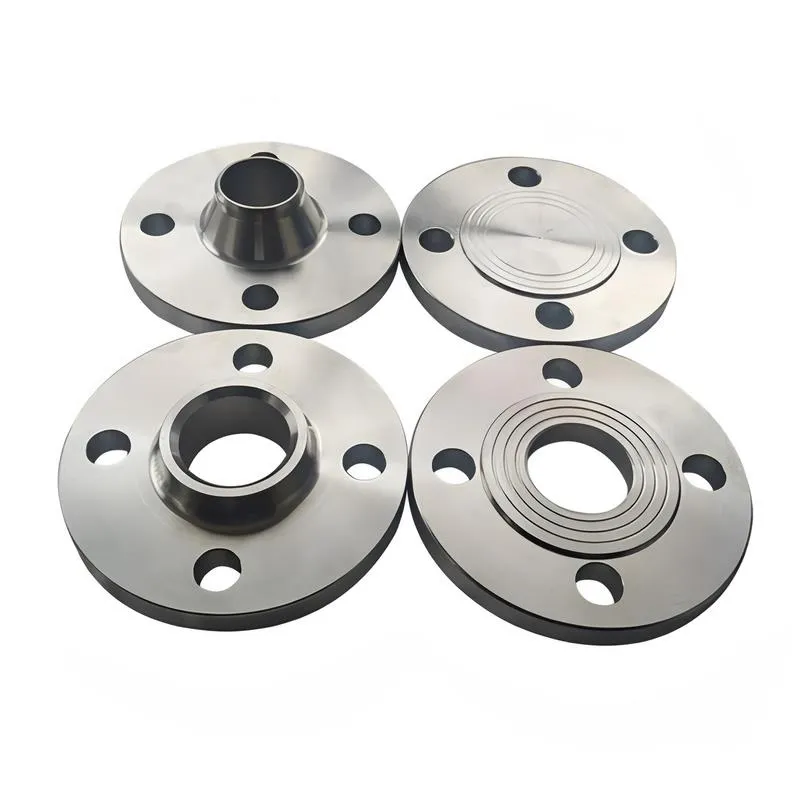
A flange—also referred to as a flange plate or rim—is a component used to connect shafts to one another, or, more commonly, to join the ends of pipes. Flanges are also utilized at the inlet and outlet ports of equipment to facilitate connections between two devices—for instance, the flange on a speed reducer. A "flange connection" or "flanged joint" refers to a detachable joint assembly comprising three interconnected elements—a flange, a gasket, and bolts—that together form a sealed structural unit. In the context of piping systems, a "pipe flange" specifically denotes a flange used for plumbing within the installation; when applied to equipment, it refers to the inlet or outlet flange of that specific device. Flanges feature a series of holes through which bolts are inserted to securely fasten the two flanges together, while a gasket placed between the flanges ensures a leak-proof seal. Flanges are broadly categorized into three types: threaded (screw-in) flanges, welded flanges, and clamp-type flanges. Flanges are invariably used in pairs; threaded flanges are suitable for low-pressure piping applications, whereas welded flanges are required for systems operating at pressures exceeding 4 kilograms per square centimeter. A sealing gasket is inserted between the two flange plates, which are then firmly secured using bolts. The thickness of a flange—as well as the specifications of the bolts used to fasten it—vary depending on the specific pressure rating required for the application. When connecting equipment such as water pumps or valves to piping systems, the corresponding connection points on these devices are often manufactured in the shape of a matching flange; this method of attachment is also referred to as a "flange connection." Generally, any connecting component that utilizes bolts to join and seal the perimeters of two flat surfaces—such as the joints in ventilation ducts—is termed a "flange"; such components may collectively be classified as "flange-type parts." However, since such a connection often constitutes merely a *portion* of a larger device—for instance, the interface between a flange and a water pump—it would be inappropriate to classify the entire water pump itself as a "flange-type part." Conversely, smaller components—such as valves—that feature such flanged interfaces may indeed be appropriately categorized as "flange-type parts."
-:-
For detailed product information, please contact sales.
-:
MetalTek MTEK 80 Cast UNS F45000 Abrasion Resistant Cast Iron Flange Product Information
-:-
For detailed product information, please contact sales.
-:
MetalTek MTEK 80 Cast UNS F45000 Abrasion Resistant Cast Iron Flange Synonyms
-:-
For detailed product information, please contact sales.
-:
MetalTek MTEK 80 Cast UNS F45000 Abrasion Resistant Cast Iron Product Information
-:-
For detailed product information, please contact sales.
-:
## **MetalTek MTEK 80 (UNS F45000) High-Chromium Abrasion Resistant White Cast Iron**
### **1. Product Overview**
MetalTek MTEK 80, standardized under **UNS F45000**, is a premium **high-chromium white cast iron** engineered specifically for extreme abrasion resistance in aggressive wear environments. This alloy belongs to the class of martensitic white irons, where the high carbon and chromium content ensures the formation of hard chromium carbides (M₇C₃) embedded in a strong, wear-resistant martensitic matrix. The "80" designation typically refers to the target **minimum Brinell hardness of 800 HBW** in the heat-treated condition.
This material is the industry benchmark for applications involving severe sliding abrasion, high-stress grinding, and impact-associated wear, offering a superior service life compared to lower alloyed white irons and many quenched steels.
---
### **2. Chemical Composition (Typical / Specified Range)**
The abrasion resistance of MTEK 80 is derived from its carefully balanced chemistry, optimized for maximum carbide volume and matrix hardness.
| Element | Typical Range (%) | Primary Function |
| :--- | :--- | :--- |
| **Carbon (C)** | 3.0 - 3.6 | Primary carbide former; controls carbide volume and hardness. |
| **Chromium (Cr)** | 23.0 - 28.0 | Forms hard, blocky (M₇C₃) chromium carbides; provides hardenability and corrosion/oxidation resistance. |
| **Molybdenum (Mo)** | 1.5 - 3.0 | Enhances hardenability, refines microstructure, and improves toughness. |
| **Nickel (Ni)** | 0.5 - 1.5 | Austinite promoter; ensures full martensitic transformation upon heat treatment. |
| **Manganese (Mn)** | 0.5 - 1.5 | Austinite stabilizer; aids hardenability. |
| **Silicon (Si)** | 0.3 - 0.8 | Deoxidizer; controlled to avoid destabilizing carbides. |
| **Copper (Cu)** | 0 - 1.2 | Sometimes added to enhance corrosion resistance and hardenability. |
| **Sulfur (S)** | ≤ 0.05 | Impurity control. |
| **Phosphorus (P)** | ≤ 0.05 | Impurity control. |
**Microstructure:** A dense dispersion of **primary and eutectic chromium carbides (M₇C₃ type)**, comprising 30-40% by volume, within a **martensitic matrix** with retained austenite. This "hard particles in a hard matrix" structure delivers exceptional wear resistance.
---
### **3. Physical & Mechanical Properties**
#### **Physical Properties:**
* **Density:** ~7.6 g/cm³
* **Melting Range:** ~1250 - 1350 °C
* **Thermal Conductivity:** Low (~20 W/m·K at 20°C)
* **Coefficient of Thermal Expansion:** 9.5 - 10.5 x 10⁻⁶ /°C (20-400°C)
#### **Mechanical Properties (in Heat-Treated Condition):**
* **Abrasion Resistance (ASTM G65):** **Exceptional.** The benchmark for severe abrasion service.
* **Hardness:** **58 - 65 HRC (600 - 800 HBW).** The high carbide volume ensures this hardness is maintained even under high surface loads.
* **Compressive Strength:** Very High (>2000 MPa). Resists deformation under crushing loads.
* **Tensile Strength:** 450 - 650 MPa. Brittle material; tensile strength is not a primary design criterion.
* **Impact Toughness (Charpy Unnotched):** 5 - 15 J. **Low impact resistance** is the key trade-off for extreme abrasion resistance.
* **Fracture Toughness:** Low. Susceptible to cracking from thermal shock or heavy impact.
* **Modulus of Elasticity:** 200 - 210 GPa.
#### **Heat Treatment:**
MTEK 80 is supplied in the **heat-treated (hardened and tempered) condition** to achieve its optimal properties. The standard process involves:
1. **Stress Relieve (As-Cast):** ~500°C.
2. **Destabilization:** Heating to 950-1050°C, holding to allow partial dissolution of carbides and carbon enrichment of the austenite.
3. **Quenching:** Air quenching or forced air cooling to transform the carbon-enriched austenite to martensite.
4. **Tempering:** Typically at 200-450°C to relieve stresses, transform retained austenite, and achieve final hardness/toughness balance.
---
### **4. Product Applications**
MTEK 80 is specified for components subjected to severe abrasive wear, particularly in mining, mineral processing, cement, and power industries.
* **Mining & Mineral Processing:**
* **Slurry Pump Parts:** Impellers, volutes, liners, throatbushes for handling abrasive ores.
* **Crusher & Grinding Mill Components:** Roll shells, hammers, blow bars, liner plates.
* **Chute & Hopper Liners,** Screw conveyor flights.
* **Cement Industry:**
* **Vertical Roller Mill (VRM) Parts:** Rollers and table segments.
* **Ball Mill Liners,** Crusher hammers.
* **Power Generation (Coal-Fired):**
* **Pulverizer Rolls and Tires,** Ash slurry pump components.
* **Shot Blasting & Abrasive Blasting:**
* **Blast Wheel Liners,** Impellers, control cages.
* **Dredging:** Cutter head teeth, pump wear parts.
---
### **5. International & Relevant Standards**
MTEK 80 is aligned with major international standards for high-chromium abrasion-resistant cast irons.
**Primary Material Standards:**
* **ASTM A532/A532M:** *Standard Specification for Abrasion-Resistant Cast Irons*. MTEK 80 corresponds most closely to:
* **Class III Type A** (20-28% Cr, 1.5-3.0% Mo). It is considered a premium version within this class.
* **UNS Designation: F45000** (Standard designation for this alloy family).
* **ISO 21988:** *Abrasion-resistant cast irons*. Corresponds to grades like **GX 300 CrMo 27 1**.
* **DIN EN 12513:** *Founding — Abrasion resistant cast irons*. Grade **G-X 300 CrMo 27 1** is equivalent.
* **JIS G5511:** *High chromium cast irons for abrasion resistance*.
**Application & Testing Standards:**
* **ASTM G65:** *Standard Test Method for Measuring Abrasion Using the Dry Sand/Rubber Wheel Apparatus* (Common wear test).
* **ASTM E384:** *Standard Test Method for Microindentation Hardness of Materials* (for hardness verification).
---
### **6. Advantages, Limitations & Design Considerations**
#### **Advantages:**
1. **Unmatched Abrasion Resistance:** Superior to most metallic materials in high-stress abrasion.
2. **Good Corrosion/Oxidation Resistance:** High chromium content provides better resistance than low-alloy white irons.
3. **High Pressure/Compressive Strength:** Resists deformation under load.
#### **Limitations:**
1. **Low Impact & Fracture Toughness:** Cannot withstand heavy, repeated impact.
2. **Poor Machinability:** Can only be ground or machined with ceramic/carbide tools. **Components must be cast to shape.**
3. **Poor Thermal Shock Resistance:** Prone to cracking with rapid temperature changes.
4. **High Density & Cost:** Higher material and melting cost than lower-alloy alternatives.
#### **Design Considerations:**
* **Avoid Sharp Corners & Notches:** Design with generous radii to prevent stress concentration and crack initiation.
* **Account for Brittleness:** Use robust backing/support structures and ensure proper fixturing.
* **Minimize Section Thickness Variations:** To avoid casting defects and differential cooling stresses.
* **Specify Correct Heat Treatment:** Essential to achieve guaranteed properties.
* **Consider Composite Designs:** Often used as wear liners or inserts mounted on a tougher, ductile substrate.
-:-
For detailed product information, please contact sales.
-:
MetalTek MTEK 80 Cast UNS F45000 Abrasion Resistant Cast Iron Specification
Dimensions
Size:
Diameter 20-1000 mm Length <6639 mm
Size:We can customized as required
Standard:
Per your request or drawing
We can customized as required
Properties(Theoretical)
Chemical Composition
-:-
For detailed product information, please contact sales.
-:
MetalTek MTEK 80 Cast UNS F45000 Abrasion Resistant Cast Iron Properties
-:-
For detailed product information, please contact sales.
-:
Applications of MetalTek MTEK 80 Cast UNS F45000 Abrasion Resistant Cast Iron Flange
-:-
For detailed product information, please contact sales.
-:
Chemical Identifiers MetalTek MTEK 80 Cast UNS F45000 Abrasion Resistant Cast Iron Flange
-:-
For detailed product information, please contact sales.
-:
Packing of MetalTek MTEK 80 Cast UNS F45000 Abrasion Resistant Cast Iron Flange
-:-
For detailed product information, please contact sales.
-:
Standard Packing:
-:-
For detailed product information, please contact sales.
-:
Typical bulk packaging includes palletized plastic 5 gallon/25 kg. pails, fiber and Steel Flange drums to 1 ton super sacks in full container (FCL) or truck load (T/L) quantities. Research and sample quantities and hygroscopic, oxidizing or other air sensitive materials may be packaged under argon or vacuum. Solutions are packaged in polypropylene, plastic or glass jars up to palletized 3110 gallon liquid totes Special package is available on request. E FORUs’ is carefully handled to minimize damage during storage and transportation and to preserve the quality of our products in their original condition