1,We Manufacturing processes are primarily classified into four types:
1:Forging,
2:Casting,
3:Cutting,
4:Rolling.
2,We can manufacture in accordance with these standards.
Standards:
GB Series (Chinese Standards), JB Series (Machinery Standards), HG Series (Chemical Industry Standards), ASME B16.5 (American Standards), BS4504 (British Standards), DIN (German Standards), and JIS (Japanese Standards).
Internationally, there are two primary systems of pipe flange standards: the European system, represented by the German DIN standards (including those of the former Soviet Union), and the American system, represented by the US ANSI pipe flange standards. Other common standards include: the Chinese Ministry of Machinery Industry standards (JB series), the Ministry of Chemical Industry standards (HG series), the Chinese National Standard *GB/T 9112–9124-2010 Steel Pipe Flanges*, as well as US standards (ASME B16.5), British standards (BS4504), German standards (DIN), Japanese standards (JIS), and marine standards (CBM), among others.
The nominal pressure ratings for the PN series are designated by "PN" and comprise the following nine levels: PN2.5, PN6, PN10, PN16, PN25, PN40, PN63, PN100, and PN160.
The nominal pressure ratings for the Class series are designated by "Class" and comprise the following six levels: Class150, Class300, Class600, Class900, Class1500, and Class2500.
Flange Classification
1. **According to Chemical Industry Standards:** Flanges are classified as follows:
Plate Flat Welding Flange (PL), Necked Flat Welding Flange (SO), Necked Butt Welding Flange (WN), Integral Flange (IF), Socket Welding Flange (SW), Threaded Flange (Th), Butt Welding Ring Loose Flange (PJ/SE), Blind Flange (BL), Flat Welding Ring Loose Flange (PJ/PJ), and Lined Blind Flange (BL(s)).
2. **According to Petrochemical (SH) Industry Standards:** Flanges are classified as follows:
Threaded Flange (PL), Butt Welding Flange (WN), Flat Welding Flange (SO), Socket Welding Flange (SW), Loose Flange (LJ), and Blind Flange (no specific designation).
3. **According to Machinery (JB) Industry Standards:** Flanges are classified as follows:
Integral Flange, Butt Welding Flange, Plate Flat Welding Flange, Butt Welding Ring Plate Loose Flange, Flat Welding Ring Plate Loose Flange, Lap Joint Ring Plate Loose Flange, and Blind Flange.
4. **According to Connection Method/Type:** Flanges are classified as follows:
Plate Flat Welding Flange, Necked Flat Welding Flange, Necked Butt Welding Flange, Socket Welding Flange, Threaded Flange, Blind Flange, Necked Butt Welding Ring Loose Flange, Flat Welding Ring Loose Flange, Ring-Type Joint (RTJ) Flange and Blind Flange, Large-Diameter Plate Flange, Large-Diameter High-Neck Flange, Figure-8 Blind Plate, Butt Welding Ring Loose Flange, etc.
5. **According to the Component Being Connected:** Flanges can be classified into Vessel Flanges and Pipe Flanges.
6. **According to Structural Type:** Flanges include Integral Flanges, Threaded Flanges, Flat Welding Flanges, Butt Welding Flanges, Lap Joint (Loose/Swivel) Flanges, and Blind Flanges.
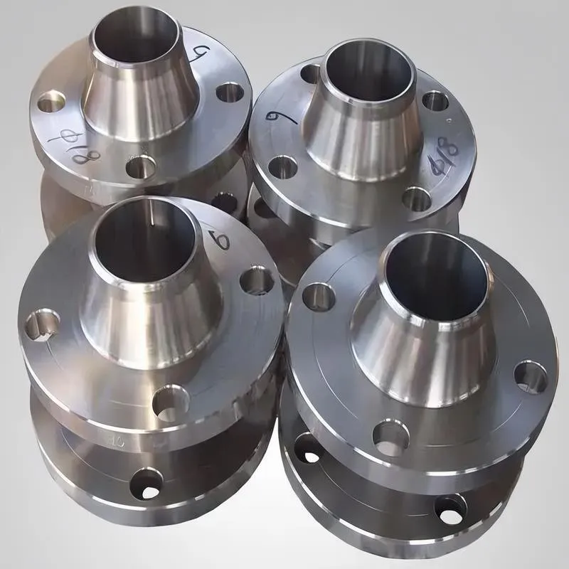
A flange—also referred to as a flange plate or rim—is a component used to connect shafts to one another, or, more commonly, to join the ends of pipes. Flanges are also utilized at the inlet and outlet ports of equipment to facilitate connections between two devices—for instance, the flange on a speed reducer. A "flange connection" or "flanged joint" refers to a detachable joint assembly comprising three interconnected elements—a flange, a gasket, and bolts—that together form a sealed structural unit. In the context of piping systems, a "pipe flange" specifically denotes a flange used for plumbing within the installation; when applied to equipment, it refers to the inlet or outlet flange of that specific device. Flanges feature a series of holes through which bolts are inserted to securely fasten the two flanges together, while a gasket placed between the flanges ensures a leak-proof seal. Flanges are broadly categorized into three types: threaded (screw-in) flanges, welded flanges, and clamp-type flanges. Flanges are invariably used in pairs; threaded flanges are suitable for low-pressure piping applications, whereas welded flanges are required for systems operating at pressures exceeding 4 kilograms per square centimeter. A sealing gasket is inserted between the two flange plates, which are then firmly secured using bolts. The thickness of a flange—as well as the specifications of the bolts used to fasten it—vary depending on the specific pressure rating required for the application. When connecting equipment such as water pumps or valves to piping systems, the corresponding connection points on these devices are often manufactured in the shape of a matching flange; this method of attachment is also referred to as a "flange connection." Generally, any connecting component that utilizes bolts to join and seal the perimeters of two flat surfaces—such as the joints in ventilation ducts—is termed a "flange"; such components may collectively be classified as "flange-type parts." However, since such a connection often constitutes merely a *portion* of a larger device—for instance, the interface between a flange and a water pump—it would be inappropriate to classify the entire water pump itself as a "flange-type part." Conversely, smaller components—such as valves—that feature such flanged interfaces may indeed be appropriately categorized as "flange-type parts."
-:-
For detailed product information, please contact sales.
-:
AISI 1018 Steel Flange, cold drawn, quenched, and tempered, 19-32 mm (0.75-1.25 in) round Product Information
-:-
For detailed product information, please contact sales.
-:
AISI 1018 Steel Flange, cold drawn, quenched, and tempered, 19-32 mm (0.75-1.25 in) round Synonyms
-:-
For detailed product information, please contact sales.
-:
AISI 1018 Steel, cold drawn, quenched, and tempered, 19-32 mm (0.75-1.25 in) round Product Information
-:-
For detailed product information, please contact sales.
-:
# **Product Specification: AISI 1018 Cold-Drawn, Quenched & Tempered Steel Bar**
## **Product Identification**
* **Standard Designation:** AISI 1018 / SAE 1018
* **UNS Number:** G10180
* **Condition:** Cold-Drawn, then Quenched & Tempered
* **Product Form:** Round Bar
* **Size Range:** 19 mm to 32 mm (0.75 inch to 1.25 inch) diameter
* **Key Feature:** Premium material combining cold-drawn precision with heat-treated strength for demanding applications
## **Overview**
AISI 1018 cold-drawn, quenched and tempered round bar represents a high-performance engineering material that combines the dimensional accuracy and surface quality of cold-drawing with the enhanced mechanical properties of heat treatment. This dual-process approach yields a product with superior strength, hardness, and fatigue resistance compared to either process alone. Specifically engineered for the 19-32 mm diameter range, this material addresses applications requiring both precision geometry and robust mechanical performance, making it ideal for critical components in automotive, industrial, and machinery applications where reliability and dimensional accuracy are paramount.
---
## **1. Chemical Composition (Weight %, AISI/SAE Standard)**
| Element | Content (%) | Metallurgical Significance in Q&T Process |
|---------|-------------|-------------------------------------------|
| **Carbon (C)** | 0.15 - 0.20 | Forms tempered martensite; critical for hardness and strength development |
| **Manganese (Mn)** | 0.60 - 0.90 | Enhances hardenability; enables effective through-hardening in 19-32 mm sections |
| **Phosphorus (P)** | ≤ 0.040 | Controlled to minimize temper embrittlement risk |
| **Sulfur (S)** | ≤ 0.050 | Impurity; may form MnS inclusions affecting anisotropy |
| **Silicon (Si)** | 0.15-0.35 | Deoxidizer; contributes to solid solution strengthening |
| **Iron (Fe)** | Balance | Matrix for martensitic transformation |
**Process-Specific Chemistry Considerations:**
- **Carbon Uniformity:** Critical for consistent hardness in Q&T
- **Mn Content:** At upper range (0.80-0.90%) preferred for 19-32 mm sections
- **Residual Elements:** Controlled to prevent quench cracking
---
## **2. Manufacturing Process Sequence**
### **Three-Stage Processing:**
1. **Cold-Drawing:**
- Starting stock: Hot-rolled 1018 bar
- Reduction: 15-30% area reduction
- Surface finish: Bright, scale-free (Ra 0.8-3.2 μm)
- Tolerance: ASTM A29 Cold-Drawn class
2. **Quenching:**
- Austenitizing: 870-900°C (1600-1650°F)
- Soak time: 30-60 minutes per inch of diameter
- Quenchant: Aggressive oil or water/polymer for 19-32 mm
- Cooling rate: Critical to avoid pearlite formation
3. **Tempering:**
- Temperature range: 425-650°C (800-1200°F)
- Time: 1-2 hours per inch of diameter
- Atmosphere: Controlled to prevent scaling/decarb
### **Process Flow Advantages:**
- **Cold-drawing first:** Establishes precise dimensions and surface
- **Heat treatment after:** Develops optimal mechanical properties
- **Minimal distortion:** Compared to heat treating before machining
- **Surface integrity:** Preserved through controlled processing
---
## **3. Physical & Mechanical Properties**
### **A. Physical Properties (Final Condition)**
- **Density:** 7.87 g/cm³ (0.284 lb/in³)
- **Elastic Modulus:** 200-205 GPa (29,000-29,700 ksi)
- **Poisson's Ratio:** 0.29
- **Thermal Conductivity:** 48-52 W/m·K
- **Coefficient of Thermal Expansion:** 11.5-12.0 × 10⁻⁶ /K (20-100°C)
- **Electrical Resistivity:** 15-18 μΩ·cm (increased due to cold work)
### **B. Mechanical Properties by Tempering Temperature (19-32 mm Range)**
| Tempering Temp | Tensile Strength | Yield Strength | Elongation | Hardness | Impact (Charpy V) |
|----------------|------------------|----------------|------------|----------|-------------------|
| **205°C (400°F)** | 1380-1520 MPa | 1170-1310 MPa | 5-10% | 42-48 HRC | 10-20 J |
| **315°C (600°F)** | 1170-1310 MPa | 1030-1170 MPa | 8-12% | 38-44 HRC | 20-35 J |
| **425°C (800°F)** | 1030-1170 MPa | 860-1030 MPa | 10-15% | 32-38 HRC | 35-55 J |
| **540°C (1000°F)** | 860-1030 MPa | 690-860 MPa | 12-18% | 25-32 HRC | 55-75 J |
| **650°C (1200°F)** | 690-860 MPa | 550-690 MPa | 15-22% | 20-27 HRC | 75-100 J |
### **C. Property Uniformity (19-32 mm Diameter)**
| Property | Surface | Mid-Radius | Center | Variation |
|----------|---------|------------|--------|-----------|
| **Hardness** | Specified ±2 HRC | -1 to -3 HRC | -2 to -5 HRC | <10% total |
| **Tensile** | Maximum | 95-98% of surface | 90-95% of surface | Controlled |
| **Impact** | Typical | Slightly higher | Highest | Through-hardened |
### **D. Comparison with Other Conditions**
| Condition | Yield Strength | Hardness | Dimensional Accuracy | Surface Finish |
|-----------|----------------|----------|---------------------|----------------|
| **Hot-Rolled** | 275-375 MPa | 130-170 HB | ±0.8 mm | Poor (scale) |
| **Cold-Drawn** | 480-690 MPa | 165-230 HB | ±0.13 mm | Excellent |
| **This Product** | 690-1310 MPa | 20-48 HRC | ±0.13 mm | Excellent |
---
## **4. Microstructural Characteristics**
### **As-Processed Structure**
- **Matrix:** Tempered martensite with cold-work substructure
- **Carbides:** Fine spheroidized cementite (tempered condition)
- **Prior Structure:** Retains some cold-drawn grain elongation
- **Inclusions:** MnS elongated in drawing direction
### **Through-Hardening Analysis (19-32 mm):**
- **19-22 mm:** Fully martensitic through section with water quench
- **22-28 mm:** Near-full hardening with aggressive oil
- **28-32 mm:** Core may contain bainite/pearlite with oil quench
### **Anisotropy Considerations:**
- **Longitudinal:** Highest strength (cold work + heat treat)
- **Transverse:** 10-15% lower impact strength
- **Radial:** Intermediate properties
---
## **5. Product Applications**
### **High-Precision Automotive Components**
- **Transmission Shafts:** Input/output shafts requiring straightness
- **Steering Components:** Precision ground rack and pinion parts
- **Fuel Injection:** High-pressure pump shafts and plungers
- **Valve Train:** Pushrods, rocker arms in performance engines
### **Industrial Machinery & Equipment**
- **Hydraulic Cylinder Rods:** 25-32 mm diameters for industrial cylinders
- **Precision Spindles:** Machine tool spindles requiring runout <0.01 mm
- **Roller Shafts:** Conveyor and processing equipment rollers
- **Gear Blanks:** Pre-hardened blanks for subsequent gear cutting
### **Fastener & Bearing Applications**
- **High-Strength Bolts:** M16-M30 high-performance fasteners
- **Bearing Races:** For custom bearing applications
- **Dowels & Pins:** Precision locating dowels in tooling
- **Axle Shafts:** Light to medium duty axle applications
### **Specialized Applications**
- **Robotics:** Arm linkages and joint components
- **Aerospace:** Non-critical structural components
- **Medical Equipment:** Precision shafts and components
- **Energy Sector:** Valve stems and pump shafts
---
## **6. International Standards & Equivalents**
### **Direct & Functional Equivalents**
| Standard System | Designation | Condition | Strength Class |
|-----------------|-------------|-----------|----------------|
| **ISO** | **ISO 683-1** | C18E4 QT | Comparable to 8.8-10.9 |
| **ASTM** | **ASTM A108** | Grade 1018 QT | Special condition |
| **DIN/EN** | **EN 10083-2** | C18E QT | Similar to 28Cr4 |
| **JIS** | **JIS G4053** | S18C-D QT | Mechanical carbon steel |
| **GB** | **GB/T 3077** | 18CrMo | Functional equivalent |
### **Property Comparison with Standard Grades**
| Grade/Condition | Yield Strength | Hardness | Typical Application |
|-----------------|----------------|----------|-------------------|
| **AISI 1018 CD** | 480-690 MPa | 165-230 HB | General machining |
| **This Product** | 690-1310 MPa | 20-48 HRC | High-strength precision |
| **AISI 4140 Q&T** | 850-1000 MPa | 28-32 HRC | Alloy alternative |
| **ISO 8.8** | 640 MPa | 22-32 HRC | Standard fastener |
---
## **7. Processing & Machining Characteristics**
### **Post-Heat Treatment Machining**
| Operation | Recommended Tools | Parameters | Challenges |
|-----------|-------------------|------------|------------|
| **Turning** | Carbide/CBN | 80-120 m/min, 0.1-0.3 mm/rev | Hardness >35 HRC requires rigid setup |
| **Drilling** | Carbide drills | 20-40 m/min, peck drilling | Work hardening in cold-drawn structure |
| **Milling** | Coated carbide | 100-150 m/min, climb milling | Interrupted cuts may cause chipping |
| **Grinding** | Al₂O₃ or CBN | 25-35 m/s, light passes | Avoid overheating to preserve temper |
### **Finishing Operations**
- **Hard Turning:** Possible to 45 HRC with PCBN tools
- **Centerless Grinding:** For final sizing and surface finish
- **Superfinishing:** For bearing surfaces (Ra <0.2 μm)
- **Polishing:** For aesthetic or low-friction surfaces
### **Secondary Heat Treatments**
- **Stress Relieving:** 150-200°C below tempering temperature
- **Surface Hardening:** Induction hardening for wear surfaces
- **Nitriding:** For increased surface hardness without distortion
- **Coating:** Electroplating with proper baking
---
## **8. Quality Assurance & Testing**
### **Required Testing Protocol**
| Test | Standard | Frequency | Acceptance Criteria |
|------|----------|-----------|-------------------|
| **Hardness Profile** | ASTM E18 | Every bar or sample | Within 3 HRC points |
| **Microhardness** | ASTM E384 | Per heat | Consistent case/core |
| **Tensile Test** | ASTM A370 | Per heat/lot | Min. specified values |
| **Microstructure** | ASTM E112 | Per heat | Tempered martensite |
| **Surface Inspection** | ASTM E125 | 100% | No quench cracks |
| **Straightness** | ASTM A29 | Sample | <0.5 mm/m |
### **Critical Quality Parameters**
1. **Decarburization Depth:** <0.13 mm maximum
2. **Surface Cracks:** None permitted
3. **Hardness Uniformity:** ±2 HRC within bar
4. **Dimensional Tolerance:** ±0.13 mm diameter
5. **Straightness:** 0.5 mm/m maximum
### **Certification Requirements**
- **EN 10204 3.2 Certificate:** Full traceability
- **Chemical Analysis:** Heat and product
- **Mechanical Tests:** Tensile, hardness, impact
- **Microphotos:** Structure documentation
- **NDT Reports:** UT or MT as specified
---
## **9. Design & Engineering Considerations**
### **Advantages of This Product**
1. **Dimensional Precision:** Cold-drawn tolerances maintained
2. **Strength-to-Weight Ratio:** Excellent for diameter range
3. **Fatigue Performance:** Enhanced by compressive surface stresses
4. **Wear Resistance:** Good for many applications
5. **Machinability:** Better than through-hardened alloy steels
### **Limitations & Considerations**
1. **Section Size Limit:** Optimal 19-28 mm; 28-32 mm requires careful quench
2. **Anisotropy:** Properties vary with direction
3. **Weldability:** Limited; requires pre/post heating
4. **Temperature Limit:** 200°C maximum continuous service
5. **Corrosion Resistance:** Similar to untreated 1018
### **Design Guidelines**
- **Fillet Radii:** Minimum 3 mm to prevent stress concentrations
- **Threads:** Preferably rolled after heat treatment
- **Hole Placement:** Minimum 2× diameter from ends
- **Surface Finishes:** Specify based on application needs
- **Straightness Requirements:** Specify if critical
---
## **10. Economic & Supply Considerations**
### **Cost Structure**
| Component | Percentage | Notes |
|-----------|------------|-------|
| **Base Material** | 40% | Cold-drawn 1018 premium |
| **Heat Treatment** | 35% | Q&T process costs |
| **Testing/Certification** | 15% | Enhanced QA requirements |
| **Profit/Margin** | 10% | Standard industry |
### **Lead Times & Availability**
- **Standard Items:** 6-10 weeks
- **Custom Tempering:** Additional 2-3 weeks
- **Minimum Order:** Typically 500-1000 kg
- **Stock Programs:** Available for common sizes/tempers
### **Total Cost of Ownership Factors**
1. **Reduced Machining:** Less material removal needed
2. **Improved Yield:** Better dimensional consistency
3. **Longer Tool Life:** Predictable machining characteristics
4. **Reduced Scrap:** Controlled heat treatment response
5. **Performance Benefits:** Extended component life
---
## **Summary**
**AISI 1018 cold-drawn, quenched and tempered round bar (19-32 mm) represents a premium engineering material solution that delivers exceptional value through combined processing benefits.** This product successfully bridges the gap between standard carbon steels and more expensive alloy alternatives, offering a unique combination of precision, strength, and reliability.
**Key Value Propositions:**
1. **Enhanced Performance:** Combines cold-drawn precision with heat-treated strength
2. **Cost Efficiency:** Achieves alloy-steel performance at carbon-steel cost
3. **Manufacturing Advantage:** Reduces secondary operations and improves yield
4. **Quality Consistency:** Controlled processing ensures reliable properties
**Technical Superiority Demonstrated By:**
- **Dimensional Accuracy:** Maintains cold-drawn tolerances (±0.13 mm)
- **Mechanical Properties:** Yield strengths from 550-1310 MPa achievable
- **Surface Quality:** Excellent finish (Ra 0.8-3.2 μm) preserved
- **Property Uniformity:** Controlled through-hardening in this diameter range
**Ideal For Applications Requiring:**
- High-strength precision shafts and axles
- Components needing both dimensional accuracy and mechanical performance
- Parts where heat treatment distortion must be minimized
- Applications where alloy steels would be over-specified
**Market Position:** This product occupies a strategic position in the materials spectrum, offering manufacturers an optimal balance of performance, cost, and manufacturability. Its availability in the 19-32 mm range makes it particularly suitable for medium-duty mechanical components across automotive, industrial, and machinery sectors.
**Selection Considerations:**
1. **For maximum strength:** Specify lower tempering temperatures (425°C/800°F)
2. **For toughness-critical applications:** Higher tempering temperatures (540-650°C)
3. **For precision components:** Consider additional grinding allowance
4. **For high-volume production:** Validate with sample lots first
**Final Recommendation:** AISI 1018 cold-drawn, quenched and tempered represents an intelligent engineering choice when component requirements exceed standard mild steel capabilities but don't justify the expense of alloy steels. Its predictable behavior, combined processing benefits, and proven performance make it a valuable option for designers and engineers seeking reliable, cost-effective solutions for demanding mechanical applications.
-:-
For detailed product information, please contact sales.
-:
AISI 1018 Steel, cold drawn, quenched, and tempered, 19-32 mm (0.75-1.25 in) round Specification
Dimensions
Size:
Diameter 20-1000 mm Length <4769 mm
Size:We can customized as required
Standard:
Per your request or drawing
We can customized as required
Properties(Theoretical)
Chemical Composition
-:-
For detailed product information, please contact sales.
-:
AISI 1018 Steel, cold drawn, quenched, and tempered, 19-32 mm (0.75-1.25 in) round Properties
-:-
For detailed product information, please contact sales.
-:
Applications of AISI 1018 Steel Flange, cold drawn, quenched, and tempered, 19-32 mm (0.75-1.25 in) round
-:-
For detailed product information, please contact sales.
-:
Chemical Identifiers AISI 1018 Steel Flange, cold drawn, quenched, and tempered, 19-32 mm (0.75-1.25 in) round
-:-
For detailed product information, please contact sales.
-:
Packing of AISI 1018 Steel Flange, cold drawn, quenched, and tempered, 19-32 mm (0.75-1.25 in) round
-:-
For detailed product information, please contact sales.
-:
Standard Packing:
-:-
For detailed product information, please contact sales.
-:
Typical bulk packaging includes palletized plastic 5 gallon/25 kg. pails, fiber and Steel Flange drums to 1 ton super sacks in full container (FCL) or truck load (T/L) quantities. Research and sample quantities and hygroscopic, oxidizing or other air sensitive materials may be packaged under argon or vacuum. Solutions are packaged in polypropylene, plastic or glass jars up to palletized 1240 gallon liquid totes Special package is available on request. E FORUs’ is carefully handled to minimize damage during storage and transportation and to preserve the quality of our products in their original condition