1,We Manufacturing processes are primarily classified into four types:
1:Forging,
2:Casting,
3:Cutting,
4:Rolling.
2,We can manufacture in accordance with these standards.
Standards:
GB Series (Chinese Standards), JB Series (Machinery Standards), HG Series (Chemical Industry Standards), ASME B16.5 (American Standards), BS4504 (British Standards), DIN (German Standards), and JIS (Japanese Standards).
Internationally, there are two primary systems of pipe flange standards: the European system, represented by the German DIN standards (including those of the former Soviet Union), and the American system, represented by the US ANSI pipe flange standards. Other common standards include: the Chinese Ministry of Machinery Industry standards (JB series), the Ministry of Chemical Industry standards (HG series), the Chinese National Standard *GB/T 9112–9124-2010 Steel Pipe Flanges*, as well as US standards (ASME B16.5), British standards (BS4504), German standards (DIN), Japanese standards (JIS), and marine standards (CBM), among others.
The nominal pressure ratings for the PN series are designated by "PN" and comprise the following nine levels: PN2.5, PN6, PN10, PN16, PN25, PN40, PN63, PN100, and PN160.
The nominal pressure ratings for the Class series are designated by "Class" and comprise the following six levels: Class150, Class300, Class600, Class900, Class1500, and Class2500.
Flange Classification
1. **According to Chemical Industry Standards:** Flanges are classified as follows:
Plate Flat Welding Flange (PL), Necked Flat Welding Flange (SO), Necked Butt Welding Flange (WN), Integral Flange (IF), Socket Welding Flange (SW), Threaded Flange (Th), Butt Welding Ring Loose Flange (PJ/SE), Blind Flange (BL), Flat Welding Ring Loose Flange (PJ/PJ), and Lined Blind Flange (BL(s)).
2. **According to Petrochemical (SH) Industry Standards:** Flanges are classified as follows:
Threaded Flange (PL), Butt Welding Flange (WN), Flat Welding Flange (SO), Socket Welding Flange (SW), Loose Flange (LJ), and Blind Flange (no specific designation).
3. **According to Machinery (JB) Industry Standards:** Flanges are classified as follows:
Integral Flange, Butt Welding Flange, Plate Flat Welding Flange, Butt Welding Ring Plate Loose Flange, Flat Welding Ring Plate Loose Flange, Lap Joint Ring Plate Loose Flange, and Blind Flange.
4. **According to Connection Method/Type:** Flanges are classified as follows:
Plate Flat Welding Flange, Necked Flat Welding Flange, Necked Butt Welding Flange, Socket Welding Flange, Threaded Flange, Blind Flange, Necked Butt Welding Ring Loose Flange, Flat Welding Ring Loose Flange, Ring-Type Joint (RTJ) Flange and Blind Flange, Large-Diameter Plate Flange, Large-Diameter High-Neck Flange, Figure-8 Blind Plate, Butt Welding Ring Loose Flange, etc.
5. **According to the Component Being Connected:** Flanges can be classified into Vessel Flanges and Pipe Flanges.
6. **According to Structural Type:** Flanges include Integral Flanges, Threaded Flanges, Flat Welding Flanges, Butt Welding Flanges, Lap Joint (Loose/Swivel) Flanges, and Blind Flanges.
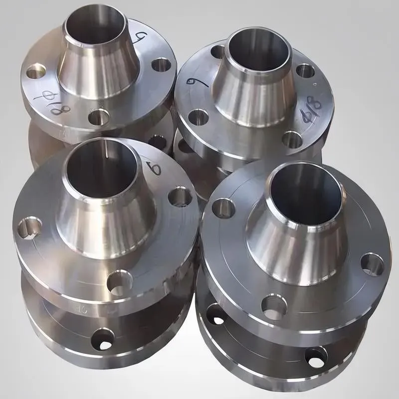
A flange—also referred to as a flange plate or rim—is a component used to connect shafts to one another, or, more commonly, to join the ends of pipes. Flanges are also utilized at the inlet and outlet ports of equipment to facilitate connections between two devices—for instance, the flange on a speed reducer. A "flange connection" or "flanged joint" refers to a detachable joint assembly comprising three interconnected elements—a flange, a gasket, and bolts—that together form a sealed structural unit. In the context of piping systems, a "pipe flange" specifically denotes a flange used for plumbing within the installation; when applied to equipment, it refers to the inlet or outlet flange of that specific device. Flanges feature a series of holes through which bolts are inserted to securely fasten the two flanges together, while a gasket placed between the flanges ensures a leak-proof seal. Flanges are broadly categorized into three types: threaded (screw-in) flanges, welded flanges, and clamp-type flanges. Flanges are invariably used in pairs; threaded flanges are suitable for low-pressure piping applications, whereas welded flanges are required for systems operating at pressures exceeding 4 kilograms per square centimeter. A sealing gasket is inserted between the two flange plates, which are then firmly secured using bolts. The thickness of a flange—as well as the specifications of the bolts used to fasten it—vary depending on the specific pressure rating required for the application. When connecting equipment such as water pumps or valves to piping systems, the corresponding connection points on these devices are often manufactured in the shape of a matching flange; this method of attachment is also referred to as a "flange connection." Generally, any connecting component that utilizes bolts to join and seal the perimeters of two flat surfaces—such as the joints in ventilation ducts—is termed a "flange"; such components may collectively be classified as "flange-type parts." However, since such a connection often constitutes merely a *portion* of a larger device—for instance, the interface between a flange and a water pump—it would be inappropriate to classify the entire water pump itself as a "flange-type part." Conversely, smaller components—such as valves—that feature such flanged interfaces may indeed be appropriately categorized as "flange-type parts."
-:-
For detailed product information, please contact sales.
-:
AISI 1025 Steel Flange, cold drawn, 19-32 mm (0.75-1.25 in) round Product Information
-:-
For detailed product information, please contact sales.
-:
AISI 1025 Steel Flange, cold drawn, 19-32 mm (0.75-1.25 in) round Synonyms
-:-
For detailed product information, please contact sales.
-:
AISI 1025 Steel, cold drawn, 19-32 mm (0.75-1.25 in) round Product Information
-:-
For detailed product information, please contact sales.
-:
# AISI 1025 Steel - Cold Drawn Round Bar Technical Datasheet
## Product Specification: 19-32 mm (0.75-1.25 in) Diameter
---
## 1. Product Overview
**AISI 1025** is a medium-carbon steel that offers an optimal balance of strength, ductility, and machinability. When processed into **cold drawn round bars** within the **19-32 mm (0.75-1.25 inch) diameter range**, this material provides enhanced mechanical properties, superior dimensional accuracy, and excellent surface finish compared to hot-rolled equivalents. The cold drawing process work-hardens the material, significantly increasing yield strength while maintaining reasonable elongation. This specific size range is particularly suitable for manufacturing precision shafts, fasteners, and mechanical components requiring consistent dimensional control and good surface quality.
The combination of controlled carbon content (0.22-0.28%) and manganese provides good hardenability, making AISI 1025 suitable for heat treatment applications while maintaining excellent weldability and formability characteristics.
---
## 2. Chemical Composition (Weight %)
| Element | AISI/SAE 1025 Specification Range (%) | Typical Analysis for 19-32 mm CD (%) | Metallurgical Influence |
|---------|---------------------------------------|--------------------------------------|--------------------------|
| **Carbon (C)** | 0.22 - 0.28 | 0.23 - 0.26 | Primary strengthening element; determines hardenability and strength |
| **Manganese (Mn)** | 0.30 - 0.60 | 0.45 - 0.55 | Enhances hardenability, strength, and deoxidizes the steel |
| **Phosphorus (P)** | ≤ 0.040 | 0.010 - 0.025 | Increases strength; excessive amounts reduce toughness |
| **Sulfur (S)** | ≤ 0.050 | 0.020 - 0.035 | Improves machinability; forms manganese sulfide inclusions |
| **Silicon (Si)** | 0.15 - 0.35 (typical) | 0.15 - 0.30 | Primary deoxidizer; solid solution strengthener |
| **Iron (Fe)** | Balance | Balance | Matrix element |
**Special Notes for 19-32 mm Cold Drawn Rounds:**
- **Carbon Control:** Typically maintained at **0.23-0.26%** to optimize strength while maintaining good cold workability
- **Manganese Optimization:** Targeted at **0.45-0.55%** to ensure uniform response to cold drawing across the section
- **Sulfur Content:** May be controlled toward the higher end of the range for improved machinability in high-volume machining applications
- **Residual Elements:** Nickel, chromium, molybdenum typically <0.20% each unless specified otherwise
---
## 3. Physical Properties
| Property | Typical Value | Test Condition / Application Relevance |
|----------|---------------|----------------------------------------|
| **Density** | 7.87 g/cm³ (0.284 lb/in³) | At 20°C; consistent across diameter range |
| **Melting Point** | 1490 - 1520°C (2714 - 2768°F) | Liquidus temperature |
| **Modulus of Elasticity (E)** | 205 GPa (29.7 × 10⁶ psi) | Important for stiffness calculations in shaft design |
| **Shear Modulus (G)** | 80 GPa (11.6 × 10⁶ psi) | Critical for torsion applications |
| **Poisson's Ratio (ν)** | 0.29 | For stress-strain relationships in multi-axial loading |
| **Thermal Conductivity** | 49.8 W/m·K | At 100°C; affects heat treatment uniformity |
| **Specific Heat Capacity** | 486 J/kg·K | At 20°C |
| **Coefficient of Thermal Expansion** | 11.4 × 10⁻⁶ /K | Over 20-100°C range; important for fitted assemblies |
| **Electrical Resistivity** | 0.162 µΩ·m | At 20°C |
| **Magnetic Properties** | Ferromagnetic | Can be magnetized; useful for某些 applications |
---
## 4. Mechanical Properties (As Cold Drawn)
### Properties by Specific Diameter:
| Mechanical Property | 19 mm (0.75") | 25 mm (1.0") | 32 mm (1.25") | Test Standard | Notes |
|---------------------|---------------|--------------|---------------|----------------|-------|
| **Tensile Strength** | 540-630 MPa (78-91 ksi) | 520-600 MPa (75-87 ksi) | 500-580 MPa (73-84 ksi) | ASTM A370 | Strength decreases slightly with increasing diameter |
| **Yield Strength (0.2% offset)** | 460-550 MPa (67-80 ksi) | 440-520 MPa (64-75 ksi) | 420-500 MPa (61-73 ksi) | ASTM A370 | Significant improvement over hot-rolled (40-60% increase) |
| **Elongation (in 50 mm)** | 12-18% | 14-20% | 16-22% | ASTM A370 | Good ductility maintained despite cold work |
| **Reduction of Area** | 40-55% | 45-60% | 50-65% | ASTM A370 | Excellent formability indicator |
| **Hardness** | 174-217 HB | 163-201 HB | 156-192 HB | ASTM E10 | Brinell typical; Rockwell B scale: 85-95 HRB |
| **Shear Strength** | 325-380 MPa (47-55 ksi) | 310-360 MPa (45-52 ksi) | 300-350 MPa (44-51 ksi) | Estimated | Typically 0.6 × tensile strength |
### Cold Drawing Effects in 19-32 mm Range:
1. **Work Hardening:** Yield strength increases by **45-65%** compared to hot-rolled condition
2. **Surface Enhancement:** Surface hardness typically **15-20% higher** than core due to greater cold work at surface
3. **Directional Properties:** Anisotropy ratio (longitudinal/transverse strength) ≈ **1.1-1.2**
4. **Residual Stress Pattern:** Compressive at surface (beneficial for fatigue), tensile in core
5. **Strain Hardening Exponent (n):** Approximately 0.15-0.20
### Comparison with Hot-Rolled 1025 (Same Diameter Range):
| Property | Cold Drawn 1025 | Hot Rolled 1025 | Improvement |
|----------|-----------------|-----------------|-------------|
| Yield Strength | 440-550 MPa | 270-330 MPa | +60-70% |
| Surface Finish | 30-60 µin RMS | 250-500 µin RMS | 80-90% smoother |
| Dimensional Tolerance | ±0.08-0.13 mm | ±0.25-0.40 mm | 3-4× tighter |
| Straightness | ≤1.5 mm/m | ≤3.0 mm/m | 50% improvement |
---
## 5. Manufacturing Process & Quality Characteristics
**Cold Drawing Process for 19-32 mm Rounds:**
```
Hot Rolled Stock → Acid Pickling (Scale Removal) → Water Rinse →
Bonderizing (Phosphate Coating) → Lubrication (Soap/Stearate) →
Cold Drawing (Single/Multi-pass) → Straightening →
Cutting to Length → Inspection → Packaging
```
**Key Process Parameters:**
- **Drawing Reduction:** 15-30% area reduction typical per pass
- **Drawing Speed:** 20-60 m/min depending on diameter and reduction
- **Die Material:** Tungsten carbide or polycrystalline diamond for precision
- **Lubrication:** Zinc phosphate coating with sodium stearate soap
**Quality Characteristics for 19-32 mm Rounds:**
- **Surface Finish:** 25-50 µin RMS (bright, smooth finish)
- **Dimensional Tolerances:** Per ASTM A108, Table 4 (Cold Finished)
- Diameter tolerance: ±0.08 mm for precision grades, ±0.13 mm for commercial
- Out-of-roundness: ≤0.4% of nominal diameter
- Length tolerance: +0/-1.5 mm for precision cut lengths
- **Straightness:** ≤1.0-1.5 mm per meter (0.04-0.06 in per 39 in)
- **Decarburization:** Maximum 0.03-0.05 mm per side for precision grades
- **Internal Soundness:** Ultrasonic testing available (ASTM A388) for critical applications
---
## 6. Primary Applications
### A. Automotive & Transportation Components
- **Drivetrain Components:** Intermediate shafts, drive shafts, stub axles
- **Steering Systems:** Pinion shafts, rack bars (after machining), linkage rods
- **Suspension:** Strut rods, stabilizer links, pivot shafts
- **Engine Components:** Camshafts (induction hardened), balance shafts, valve train parts
### B. Machinery & Industrial Equipment
- **Power Transmission:** Motor shafts, gear shafts, spindle stocks
- **Hydraulic/Pneumatic:** Piston rods, cylinder rods, valve stems
- **Material Handling:** Conveyor shafts, roller bearings, guide pins
- **Agricultural:** Implement drive shafts, PTO shafts, tillage components
### C. Fastener & Precision Components
- **High-Strength Fasteners:** Bolts (M12-M30), studs, precision pins
- **Bearing Components:** Races (after heat treatment), bearing journals
- **Tooling:** Arbor shafts, mandrels, fixture components
- **Consumer Products:** Bicycle components, exercise equipment shafts
### D. Further Processing Applications
- **Cold Heading:** Excellent for bolt manufacturing up to M24 size
- **CNC Machining:** Ideal stock for precision turned and milled components
- **Heat Treatment:** Excellent response to induction hardening and carburizing
- **Grinding:** Base material for precision ground shafts and pins
**Specific Application Examples by Diameter:**
- **19 mm:** Hydraulic piston rods, precision pins, fastener stock
- **25 mm:** Medium-duty drive shafts, spindle stocks, machinery shafts
- **32 mm:** Heavy-duty axles, large fastener stock, structural pins
---
## 7. Fabrication & Processing Characteristics
### Machinability (19-32 mm Diameter Range):
- **Machinability Rating:** 60-65% (relative to 1212 steel as 100%)
- **Recommended Cutting Parameters:**
- Turning: 35-50 m/min (115-165 SFM) with carbide inserts
- Drilling: 25-35 m/min (80-115 SFM) with HSS drills
- Milling: 40-60 m/min (130-200 SFM) with carbide end mills
- **Chip Formation:** Continuous, stringy chips; chip breakers essential
- **Surface Finish:** Achievable: 0.8-1.6 µin (32-63 µin) Ra with proper tooling
- **Tool Life:** Good with appropriate coolant and tool geometry
### Welding Characteristics:
- **Weldability Rating:** Good (Carbon Equivalent ≈ 0.40-0.45)
- CE = C + Mn/6 = 0.25 + 0.50/6 ≈ 0.33 (IIW formula)
- PCM = C + Si/30 + Mn/20 + Cu/20 + Ni/60 + Cr/20 + Mo/15 + V/10 + 5B ≈ 0.28
- **Preheat Requirements:** 100-150°C for sections >25 mm thickness
- **Post-Weld Heat Treatment:** Recommended for thick sections (>32 mm)
- **Recommended Welding Processes:**
- GTAW (TIG): ER70S-2, ER70S-6 filler
- GMAW (MIG): ER70S-6 with 75% Ar/25% CO₂
- SMAW (Stick): E7018, E7018-1 electrodes
- **Welding Precautions:** Control heat input to avoid excessive HAZ hardness
### Cold Forming & Machining:
- **Cold Bending:** Minimum bend radius = 2.5 × diameter
- **Thread Rolling:** Excellent for roll-formed threads
- **Cold Heading:** Good for upset ratios up to 2.5:1
- **Grindability:** Excellent; produces fine surface finishes
---
## 8. Heat Treatment Response
**Available Heat Treatments for 19-32 mm Rounds:**
| Treatment | Parameters | Resulting Properties | Applications |
|-----------|------------|---------------------|--------------|
| **Stress Relieving** | 550-650°C, 1 hr/25mm, furnace cool | Reduces residual stresses by 80-95% | After heavy machining or cold working |
| **Annealing** | 840-870°C, furnace cool to 600°C | 150-180 HB; optimal machinability | Improving machinability or cold formability |
| **Normalizing** | 870-900°C, air cool | 160-190 HB; refined grain structure | General property improvement |
| **Carburizing** | 900-925°C, gas atmosphere, oil quench | Case: 58-63 HRC; Core: 25-35 HRC | Wear surfaces with tough core |
| **Induction Hardening** | 850-900°C, water/oil quench | Case: 52-58 HRC; Depth: 1-6 mm | Localized hardening of bearing surfaces |
| **Through Hardening** | 830-860°C, oil quench, 400-600°C temper | 25-40 HRC throughout | Components requiring uniform hardness |
**Case Hardening Performance (19-32 mm Rounds):**
- **Effective Case Depth:** 0.5-2.0 mm typical (to 50 HRC)
- **Case Hardness:** 58-63 HRC achievable with proper quench
- **Core Properties:** 25-35 HRC maintains excellent toughness
- **Distortion Control:** Minimal due to symmetrical section and cold drawn stability
**Hardenability Data (Jominy End-Quench Test):**
- Distance from quenched end: 1/16" (1.6 mm) → 45-50 HRC
- Distance from quenched end: 1/4" (6.4 mm) → 35-40 HRC
- Distance from quenched end: 1/2" (12.7 mm) → 25-30 HRC
---
## 9. International Standards & Cross-References
| Country/Region | Standard Number | Grade Designation | Condition | Notes & Comparison |
|----------------|-----------------|-------------------|-----------|-------------------|
| **United States** | ASTM A108 | Grade 1025 | Cold drawn | Primary specification |
| **United States** | SAE J403 | 1025 | - | Chemical composition |
| **United States** | SAE J412 | 1025 | - | Material specification |
| **Europe** | EN 10083-2 | 1.1158 (C25E) | - | Closest equivalent (0.22-0.29% C) |
| **Germany** | DIN 17200 | 1.1158 | - | C25E equivalent |
| **Japan** | JIS G4051 | S25C | - | Very similar (0.22-0.28% C) |
| **International** | ISO 683-18 | Type 1.4 | - | Medium carbon steel classification |
| **United Kingdom** | BS 970 | 080M25 | - | Equivalent grade |
| **China** | GB/T 699 | 25# | - | Similar grade (0.22-0.30% C) |
| **India** | IS 5517 | C25 | - | Carbon steel with 0.20-0.30% C |
| **Canada** | CSA G40.21 | 300W | - | Similar mechanical properties |
**Procurement Specifications for 19-32 mm Cold Drawn 1025:**
```
MATERIAL: ASTM A108 Grade 1025, Cold Drawn
CONDITION: As drawn (or stress relieved if specified)
DIAMETER: [Specify exact diameter: 19, 22, 25, 28, 32 mm, etc.]
TOLERANCE: ASTM A108 Table 4, Grade B (±0.08 mm) or Grade C (±0.13 mm)
STRAIGHTNESS: ≤1.0 mm per meter (precision), ≤1.5 mm/m (commercial)
SURFACE FINISH: Bright finish, 25-50 µin RMS
LENGTH: [Specify cut length or random mill lengths]
CERTIFICATION: EN 10204 3.1 Mill Test Certificate
SPECIAL REQUIREMENTS: [Ultrasonic testing, special packaging, etc.]
```
---
## 10. Quality Assurance & Testing
**Standard Testing Protocol:**
1. **Chemical Analysis:** Optical emission spectroscopy per heat/lot (ASTM E415)
2. **Tensile Testing:** Minimum one test per 10 tons or per heat (ASTM A370)
3. **Hardness Testing:** Brinell (ASTM E10) or Rockwell (ASTM E18)
4. **Dimensional Inspection:** 100% diameter, roundness, straightness check
5. **Surface Inspection:** Visual per ASTM A484, dye penetrant optional
**Available Quality Classes:**
- **Commercial Quality (CQ):** Standard cold drawn bars for general applications
- **Special Quality (SQ):** Enhanced internal soundness, controlled microstructure
- **Cold Heading Quality (CHQ):** Optimized for cold forming operations
- **Shafting Quality (SQ-SR):** Premium grade with stress relieving, tight tolerances
- **Bearing Quality (BQ):** Ultra-clean steel with controlled inclusion content
**Typical Certifications:**
- Mill Test Certificate 3.1 or 3.2 per EN 10204
- Chemical and Mechanical Test Reports with traceability
- RoHS/REACH compliance certificates
- Third-party inspection certificates (SGS, TÜV, Lloyd's, etc.)
**Non-Destructive Testing Available:**
- Ultrasonic Testing (ASTM A388): For internal defect detection
- Magnetic Particle Inspection (ASTM A275): For surface and near-surface defects
- Eddy Current Testing: For surface flaw detection
---
## 11. Storage, Handling & Shelf Life
**Storage Recommendations:**
- **Environment:** Indoor, dry, temperature-controlled preferred (RH <60%)
- **Support:** Proper racking with supports every 1.0-1.2 meters
- **Stacking:** Maximum 1.5 meters height with separators between layers
- **Protection:** VCI paper wrapping or light oil coating for storage >3 months
- **Identification:** Maintain heat/lot tags throughout storage and handling
**Corrosion Protection:**
- **Natural Protection:** Bright finish provides some corrosion resistance
- **Additional Protection:**
- Light oil film for 3-6 month storage
- VCI paper for 6-12 month storage
- Electroplating or painting for long-term protection
- **Corrosion Rate:** ~0.05-0.10 mm/year in indoor industrial environment
**Handling Guidelines:**
- Use nylon slings or magnetic lifters appropriate for the diameter
- Avoid dropping or impact loading to prevent surface damage
- Protect machined surfaces or threads with appropriate covers
- Implement FIFO (First-In-First-Out) inventory management
---
## 12. Technical Design Considerations
### For 19-32 mm Shaft Design:
- **Fatigue Endurance Limit:** 220-260 MPa (polished surface, R=-1)
- **Surface Finish Factor:** 0.9 for cold drawn finish, 0.8-1.0 depending on condition
- **Size Effect Factor:** 0.85-0.95 for 19-32 mm diameter range
- **Stress Concentration Factors:**
- Shoulder fillet (r/d=0.1): Kt ≈ 1.7
- Keyway: Kt ≈ 2.0-2.5
- Transverse hole (d/D=0.2): Kt ≈ 2.3
### Allowable Loads (Conservative Design Values):
| Diameter | Static Axial Load (kN) | Bending Moment (Nm) | Torsion (Nm) | Critical Speed* (RPM) |
|----------|------------------------|---------------------|--------------|------------------------|
| 19 mm | 130-155 | 90-110 | 140-165 | 8500-9500 |
| 25 mm | 215-260 | 190-230 | 310-370 | 4800-5500 |
| 32 mm | 330-400 | 400-480 | 670-800 | 2900-3400 |
*Based on simply supported shaft, L=1000mm, steel density
### Thermal Design Considerations:
- **Maximum Continuous Service Temperature:** 350°C (660°F)
- **Short-Term Exposure Limit:** 425°C (800°F)
- **Creep Considerations:** Significant above 300°C for stressed applications
- **Thermal Stress:** Important for constrained assemblies due to CTE of 11.4×10⁻⁶/K
---
## 13. Economic Considerations
**Cost Factors for 19-32 mm Cold Drawn 1025:**
- **Base Price:** Typically **30-40% premium** over hot-rolled equivalent
- **Volume Discounts:** Significant for quantities >5 tons (10-20% discount)
- **Special Processing Costs:**
- Precision tolerances (±0.05 mm): +15-25%
- Special straightness (≤0.5 mm/m): +10-20%
- Stress relieving: +5-10%
- Testing/certification: +3-8%
- **Regional Price Variations:** North America vs. Europe vs. Asia differences
**Value Analysis:**
- **Cost per Strength Unit:** Excellent compared to alloy steels
- **Machining Cost Savings:** Reduced machining time vs. hot-rolled (20-30% saving)
- **Material Utilization:** Better dimensional accuracy reduces scrap (5-10% saving)
- **Tool Life:** Improved surface finish extends cutting tool life (15-25% longer)
**Total Cost of Ownership Considerations:**
- Reduced secondary processing requirements
- Lower inspection costs due to consistent quality
- Reduced rejection rates in automated machining
- Lower inventory costs due to predictable performance
---
## 14. Comparison with Competing Grades
| Grade | Carbon Range | Typical Yield (25mm) | Machinability | Relative Cost | Best Application Match |
|-------|--------------|----------------------|---------------|---------------|------------------------|
| **1025 Cold Drawn** | 0.22-0.28% | 440-520 MPa | 60-65% | 1.00 (baseline) | Balanced strength, machinability, cost |
| 1022 Cold Drawn | 0.18-0.23% | 420-500 MPa | 65-70% | 0.95-0.98 | Better weldability, slightly lower strength |
| 1030 Cold Drawn | 0.28-0.34% | 460-540 MPa | 55-60% | 1.05-1.10 | Higher strength requirements |
| 1045 Cold Drawn | 0.43-0.50% | 500-600 MPa | 50-55% | 1.15-1.25 | High strength, heat treatable |
| 4140 Cold Drawn | 0.38-0.43% | 650-750 MPa | 50-55% | 1.40-1.60 | High strength, good toughness |
**Selection Guidelines:**
- **Choose 1025 CD when:** You need balanced properties, good machinability, and cost-effectiveness
- **Consider alternatives when:** Special properties needed (higher strength, better corrosion resistance, etc.)
---
## 15. Limitations & Special Considerations
1. **Temperature Limitations:**
- Maximum service temperature: 350°C (660°F) continuous
- Properties degrade above 200°C (390°F) due to tempering of cold work
- Not suitable for high-temperature applications (>400°C)
2. **Corrosion Resistance:**
- Equivalent to other carbon steels (poor without protection)
- Requires protective coatings for corrosive environments
- Not suitable for marine or chemical exposure without adequate protection
3. **Size Limitations:**
- Maximum practical cold drawing diameter: ~75 mm (3")
- Properties vary near size extremes (surface-to-core gradient increases)
- Difficult to maintain tight tolerances above 50 mm diameter
4. **Anisotropy Considerations:**
- Directional properties affect performance in multi-axial loading
- Stress relieving recommended for complex stress states
- Fatigue properties better in longitudinal direction
5. **Welding Limitations:**
- Preheat required for sections >25 mm
- Post-weld heat treatment recommended for critical applications
- HAZ may have reduced properties due to tempering of cold work
6. **Environmental & Safety:**
- Standard steel handling precautions apply
- Dust from machining may require ventilation
- Proper disposal of cutting fluids and swarf required
---
## 16. Future Trends & Developments
1. **Sustainability Initiatives:**
- Increased use of recycled content (targeting >90% in some mills)
- Energy-efficient drawing processes with regenerative drives
- Reduced lubricant consumption through advanced coating technologies
2. **Quality Advancements:**
- Real-time monitoring of drawing forces and temperatures
- Advanced non-destructive testing integration
- Digital material certificates with full traceability
3. **Processing Innovations:**
- Controlled cooling after drawing for optimized properties
- In-line stress relieving technologies
- Advanced surface finishing techniques
4. **Customization Trends:**
- Tailored chemistries for specific applications
- Just-in-time manufacturing with reduced lead times
- Application-specific property optimization
---
*Technical Disclaimer: This datasheet provides typical values and characteristics for cold drawn AISI 1025 round bars in the 19-32 mm diameter range. Actual properties may vary depending on:*
- *Manufacturer and specific processing parameters*
- *Heat treatment history and condition*
- *Testing methods and specimen preparation*
- *Specific heat/lot variations*
*For critical applications:*
1. *Always consult the manufacturer's certified test reports*
2. *Conduct appropriate validation testing for your specific application*
3. *Consider all relevant factors including loading conditions, environment, safety factors, and regulatory requirements*
4. *Comply with all applicable design codes, standards, and regulations*
*The information contained herein is for general guidance and should not replace professional engineering analysis or specific material testing. The manufacturer's specifications and recommendations should always take precedence.*
-:-
For detailed product information, please contact sales.
-:
AISI 1025 Steel, cold drawn, 19-32 mm (0.75-1.25 in) round Specification
Dimensions
Size:
Diameter 20-1000 mm Length <4781 mm
Size:We can customized as required
Standard:
Per your request or drawing
We can customized as required
Properties(Theoretical)
Chemical Composition
-:-
For detailed product information, please contact sales.
-:
AISI 1025 Steel, cold drawn, 19-32 mm (0.75-1.25 in) round Properties
-:-
For detailed product information, please contact sales.
-:
Applications of AISI 1025 Steel Flange, cold drawn, 19-32 mm (0.75-1.25 in) round
-:-
For detailed product information, please contact sales.
-:
Chemical Identifiers AISI 1025 Steel Flange, cold drawn, 19-32 mm (0.75-1.25 in) round
-:-
For detailed product information, please contact sales.
-:
Packing of AISI 1025 Steel Flange, cold drawn, 19-32 mm (0.75-1.25 in) round
-:-
For detailed product information, please contact sales.
-:
Standard Packing:
-:-
For detailed product information, please contact sales.
-:
Typical bulk packaging includes palletized plastic 5 gallon/25 kg. pails, fiber and Steel Flange drums to 1 ton super sacks in full container (FCL) or truck load (T/L) quantities. Research and sample quantities and hygroscopic, oxidizing or other air sensitive materials may be packaged under argon or vacuum. Solutions are packaged in polypropylene, plastic or glass jars up to palletized 1252 gallon liquid totes Special package is available on request. E FORUs’ is carefully handled to minimize damage during storage and transportation and to preserve the quality of our products in their original condition


")


