1,We Manufacturing processes are primarily classified into four types:
1:Forging,
2:Casting,
3:Cutting,
4:Rolling.
2,We can manufacture in accordance with these standards.
Standards:
GB Series (Chinese Standards), JB Series (Machinery Standards), HG Series (Chemical Industry Standards), ASME B16.5 (American Standards), BS4504 (British Standards), DIN (German Standards), and JIS (Japanese Standards).
Internationally, there are two primary systems of pipe flange standards: the European system, represented by the German DIN standards (including those of the former Soviet Union), and the American system, represented by the US ANSI pipe flange standards. Other common standards include: the Chinese Ministry of Machinery Industry standards (JB series), the Ministry of Chemical Industry standards (HG series), the Chinese National Standard *GB/T 9112–9124-2010 Steel Pipe Flanges*, as well as US standards (ASME B16.5), British standards (BS4504), German standards (DIN), Japanese standards (JIS), and marine standards (CBM), among others.
The nominal pressure ratings for the PN series are designated by "PN" and comprise the following nine levels: PN2.5, PN6, PN10, PN16, PN25, PN40, PN63, PN100, and PN160.
The nominal pressure ratings for the Class series are designated by "Class" and comprise the following six levels: Class150, Class300, Class600, Class900, Class1500, and Class2500.
Flange Classification
1. **According to Chemical Industry Standards:** Flanges are classified as follows:
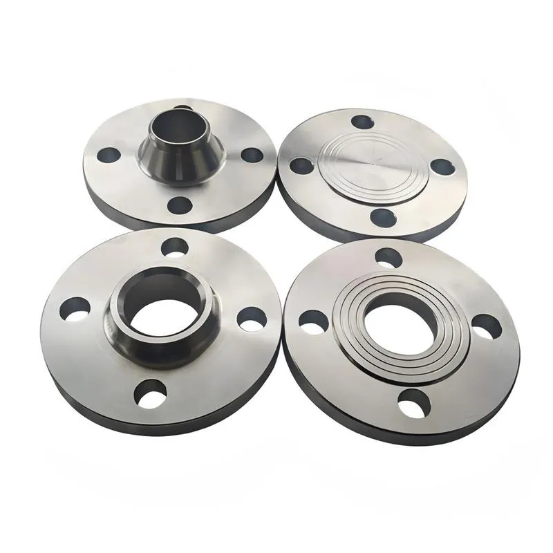
Plate Flat Welding Flange (PL), Necked Flat Welding Flange (SO), Necked Butt Welding Flange (WN), Integral Flange (IF), Socket Welding Flange (SW), Threaded Flange (Th), Butt Welding Ring Loose Flange (PJ/SE), Blind Flange (BL), Flat Welding Ring Loose Flange (PJ/PJ), and Lined Blind Flange (BL(s)).
2. **According to Petrochemical (SH) Industry Standards:** Flanges are classified as follows:
Threaded Flange (PL), Butt Welding Flange (WN), Flat Welding Flange (SO), Socket Welding Flange (SW), Loose Flange (LJ), and Blind Flange (no specific designation).
3. **According to Machinery (JB) Industry Standards:** Flanges are classified as follows:
Integral Flange, Butt Welding Flange, Plate Flat Welding Flange, Butt Welding Ring Plate Loose Flange, Flat Welding Ring Plate Loose Flange, Lap Joint Ring Plate Loose Flange, and Blind Flange.
4. **According to Connection Method/Type:** Flanges are classified as follows:
Plate Flat Welding Flange, Necked Flat Welding Flange, Necked Butt Welding Flange, Socket Welding Flange, Threaded Flange, Blind Flange, Necked Butt Welding Ring Loose Flange, Flat Welding Ring Loose Flange, Ring-Type Joint (RTJ) Flange and Blind Flange, Large-Diameter Plate Flange, Large-Diameter High-Neck Flange, Figure-8 Blind Plate, Butt Welding Ring Loose Flange, etc.
5. **According to the Component Being Connected:** Flanges can be classified into Vessel Flanges and Pipe Flanges.
6. **According to Structural Type:** Flanges include Integral Flanges, Threaded Flanges, Flat Welding Flanges, Butt Welding Flanges, Lap Joint (Loose/Swivel) Flanges, and Blind Flanges.
A flange—also referred to as a flange plate or rim—is a component used to connect shafts to one another, or, more commonly, to join the ends of pipes. Flanges are also utilized at the inlet and outlet ports of equipment to facilitate connections between two devices—for instance, the flange on a speed reducer. A "flange connection" or "flanged joint" refers to a detachable joint assembly comprising three interconnected elements—a flange, a gasket, and bolts—that together form a sealed structural unit. In the context of piping systems, a "pipe flange" specifically denotes a flange used for plumbing within the installation; when applied to equipment, it refers to the inlet or outlet flange of that specific device. Flanges feature a series of holes through which bolts are inserted to securely fasten the two flanges together, while a gasket placed between the flanges ensures a leak-proof seal. Flanges are broadly categorized into three types: threaded (screw-in) flanges, welded flanges, and clamp-type flanges. Flanges are invariably used in pairs; threaded flanges are suitable for low-pressure piping applications, whereas welded flanges are required for systems operating at pressures exceeding 4 kilograms per square centimeter. A sealing gasket is inserted between the two flange plates, which are then firmly secured using bolts. The thickness of a flange—as well as the specifications of the bolts used to fasten it—vary depending on the specific pressure rating required for the application. When connecting equipment such as water pumps or valves to piping systems, the corresponding connection points on these devices are often manufactured in the shape of a matching flange; this method of attachment is also referred to as a "flange connection." Generally, any connecting component that utilizes bolts to join and seal the perimeters of two flat surfaces—such as the joints in ventilation ducts—is termed a "flange"; such components may collectively be classified as "flange-type parts." However, since such a connection often constitutes merely a *portion* of a larger device—for instance, the interface between a flange and a water pump—it would be inappropriate to classify the entire water pump itself as a "flange-type part." Conversely, smaller components—such as valves—that feature such flanged interfaces may indeed be appropriately categorized as "flange-type parts."
-:-
For detailed product information, please contact sales.
-:
AISI 3310 Carburizing Bearing Steel Flange Product Information
-:-
For detailed product information, please contact sales.
-:
AISI 3310 Carburizing Bearing Steel Flange Synonyms
-:-
For detailed product information, please contact sales.
-:
AISI 3310 Carburizing Bearing Steel Product Information
-:-
For detailed product information, please contact sales.
-:
# **Technical Data Sheet: AISI 3310 Carburizing Bearing Steel**
## **1. MATERIAL OVERVIEW**
**AISI 3310** is a **nickel-chromium alloy carburizing steel** specifically designed for bearing applications and other heavily loaded components requiring exceptional surface durability combined with a tough, ductile core. This through-hardening carburizing steel belongs to the 3300 series of alloy steels, characterized by its balanced nickel-chromium composition that provides excellent hardenability, fatigue resistance, and impact toughness. Particularly valued in bearing applications, it offers superior performance under high contact stresses and demanding operating conditions through the combination of a hard, wear-resistant case and a resilient, shock-absorbing core.
## **2. INTERNATIONAL STANDARD DESIGNATIONS**
| Standard System | Designation | Equivalent Standard | Application Focus |
|----------------|-------------|---------------------|-------------------|
| **UNS** | **G33106** | Unified Numbering System | Universal designation |
| **AISI/SAE** | **3310** | SAE J404, J412 | Standard grade |
| **ASTM** | **A534** | Carburizing Steel for Bearings | Bearing-specific spec |
| **AMS** | **6260** | Aircraft Quality | Aerospace bearing standard |
| **EN (Europe)** | **18NiCrMo14-6** | EN 10084 (1.6565) | European equivalent |
| **DIN (Germany)** | **18NiCrMo14-6** | DIN 17210 | German standard |
| **JIS (Japan)** | **SNC815H** | JIS G4052 | Japanese carburizing steel |
| **ISO** | **Type 18NiCrMo14-6** | ISO 683-11 | International standard |
| **GB (China)** | **20CrNi2Mo** | GB/T 3077 | Chinese equivalent |
## **3. CHEMICAL COMPOSITION SPECIFICATION**
### **Standard Composition Ranges (SAE J404)**
| Element | Minimum (%) | Maximum (%) | Typical (%) | Metallurgical Function |
|---------|-------------|-------------|-------------|------------------------|
| **Carbon (C)** | 0.08 | 0.13 | 0.10 | Controls core strength, minimal for toughness |
| **Manganese (Mn)** | 0.40 | 0.70 | 0.55 | Enhances hardenability, refines grain |
| **Phosphorus (P)** | - | 0.025 | 0.015 | Residual impurity (strictly controlled) |
| **Sulfur (S)** | - | 0.025 | 0.015 | Residual impurity (strictly controlled) |
| **Silicon (Si)** | 0.15 | 0.35 | 0.25 | Deoxidizer, solid solution strengthening |
| **Nickel (Ni)** | 3.25 | 3.75 | 3.50 | Provides toughness, hardenability, fatigue resistance |
| **Chromium (Cr)** | 1.40 | 1.75 | 1.60 | Enhances hardenability, wear resistance |
| **Molybdenum (Mo)** | 0.08 | 0.15 | 0.12 | Improves hardenability, reduces temper embrittlement |
| **Iron (Fe)** | Balance | Balance | Balance | Base metal |
### **Special Quality Requirements for Bearing Applications:**
- **Inclusion Control**: Typically ASTM E45 A1, B1, C1, D1 maximum (very clean)
- **Segregation Control**: Banding minimized through proper processing
- **Grain Size**: ASTM 6 or finer (typically ASTM 7-8)
- **Decarburization**: Tightly controlled in finished products
## **4. PHYSICAL PROPERTIES**
| Property | Value Range | Typical | Unit | Conditions/Notes |
|----------|-------------|---------|------|------------------|
| **Density** | 7.85-7.87 | 7.86 | g/cm³ | At 20°C |
| **Melting Point** | 1480-1510 | 1495 | °C | Liquidus temperature |
| **Modulus of Elasticity** | 200-205 | 202 | GPa | 29,300 ksi |
| **Shear Modulus** | 78-82 | 80 | GPa | 11,600 ksi |
| **Poisson's Ratio** | 0.29-0.30 | 0.295 | - | Typical |
| **Thermal Conductivity** | 42-45 | 43.5 | W/m·K | At 20°C |
| **Coefficient of Thermal Expansion** | 11.5-12.0 | 11.8 | μm/m·°C | 20-200°C range |
| **Specific Heat Capacity** | 460-480 | 470 | J/kg·K | At 20°C |
| **Electrical Resistivity** | 0.25-0.30 | 0.27 | μΩ·m | At 20°C |
| **Magnetic Properties** | Ferromagnetic | - | - | Below Curie point |
| **Density (Core)** | 7.86 | 7.86 | g/cm³ | After heat treatment |
## **5. MECHANICAL PROPERTIES**
### **Core Properties (After Carburizing & Heat Treatment)**
| Property | Minimum | Typical | Maximum | Unit | Condition |
|----------|---------|---------|---------|------|-----------|
| **Tensile Strength** | 1000 | 1100-1300 | 1400 | MPa | Depends on tempering |
| **Yield Strength (0.2%)** | 850 | 950-1150 | 1200 | MPa | Core properties |
| **Elongation (A50mm)** | 10 | 12-15 | 18 | % | Core ductility |
| **Reduction of Area** | 40 | 45-55 | 60 | % | Core toughness |
| **Impact Energy (Charpy V)** | 40 | 50-70 | 80 | J | Room temperature |
| **Core Hardness** | 30 | 32-38 | 40 | HRC | After tempering |
### **Case Properties (After Carburizing)**
| Property | Value Range | Typical | Unit |
|----------|-------------|---------|------|
| **Surface Hardness** | 58-63 | 60-62 | HRC |
| **Effective Case Depth** | 0.8-2.5 | 1.0-1.5 | mm (to 550 HV) |
| **Case Carbon Content** | 0.75-0.90 | 0.80-0.85 | % |
| **Residual Stress** | -300 to -500 | -400 | MPa (compressive) |
| **Case Toughness** | Good | - | - |
### **Properties by Section Size**
| Effective Section (mm) | Core Hardness (HRC) | Tensile Strength (MPa) | Fatigue Limit (MPa) |
|------------------------|---------------------|------------------------|---------------------|
| **Up to 25** | 35-40 | 1200-1400 | 550-650 |
| **25-50** | 32-38 | 1100-1300 | 500-600 |
| **50-100** | 30-35 | 1000-1200 | 450-550 |
| **100-150** | 28-33 | 900-1100 | 400-500 |
## **6. HEAT TREATMENT CHARACTERISTICS**
### **Carburizing Parameters**
| Parameter | Recommended Range | Optimal | Notes |
|-----------|------------------|---------|-------|
| **Temperature** | 900-940°C | 925°C | Gas or vacuum carburizing |
| **Time** | 4-20 hours | Case depth dependent | Typically 8-12h for 1.2mm |
| **Carbon Potential** | 0.80-0.90% | 0.85% | Controlled atmosphere |
| **Diffusion Cycle** | Optional | Recommended | Reduces carbides at surface |
| **Quenching** | Direct from carburizing or reheat | Direct preferred | Oil quench |
### **Heat Treatment Sequence**
1. **Pre-machining**: Rough machine in annealed condition
2. **Carburizing**: 925°C at 0.85% C potential for required time
3. **Quenching**: Oil quench from 830-850°C (direct or reheat)
4. **Deep Freezing**: Optional at -70°C to -100°C (reduces retained austenite)
5. **Tempering**: 150-200°C for 2-4 hours (stress relief, adjust hardness)
### **Hardenability Data (Jominy Test)**
| Distance from Quenched End (1/16") | Core Hardness (HRC) | Case Hardness (HRC) |
|------------------------------------|---------------------|---------------------|
| 1 | 40-45 | 60-63 |
| 4 | 38-43 | 58-62 |
| 8 | 35-40 | - |
| 12 | 32-37 | - |
| 16 | 30-35 | - |
| 20 | 28-33 | - |
### **Microstructural Requirements**
- **Case Structure**: Fine martensite with minimal retained austenite (<15%)
- **Carbide Distribution**: Fine, dispersed carbides preferred
- **Core Structure**: Tempered martensite or bainite
- **Grain Size**: ASTM 7 or finer in both case and core
## **7. BEARING-SPECIFIC PROPERTIES**
### **Fatigue Performance**
| Property | Value Range | Typical | Unit | Test Method |
|----------|-------------|---------|------|-------------|
| **Contact Fatigue Life (L₁₀)** | 10⁷-10⁸ cycles | - | - | Rolling contact fatigue |
| **Fatigue Limit (Rotating Bending)** | 500-600 | 550 | MPa | DIN 50100 |
| **Pitting Resistance** | Excellent | - | - | Field performance |
| **Spalling Resistance** | Very Good | - | - | Bearing applications |
### **Wear Characteristics**
- **Abrasive Wear Resistance**: Excellent (case hardness 60+ HRC)
- **Adhesive Wear Resistance**: Very Good (nickel content helps)
- **Fretting Resistance**: Good with proper surface finish
- **Scoring Resistance**: Excellent with proper lubrication
### **Dimensional Stability**
- **Heat Treatment Distortion**: Low to moderate (good hardenability)
- **Growth during Carburizing**: 0.1-0.2% typical
- **Machining Allowance**: 0.2-0.5mm per side recommended
- **Grindability**: Excellent after heat treatment
## **8. MANUFACTURING & PROCESSING**
### **Machinability**
- **Annealed Condition**: 60% of B1112 steel
- **Hardened Condition**: 25% of B1112 steel
- **Relative Index**: 0.65 (compared to 1.0 for 1212)
**Recommended Machining Parameters (Annealed, 180-200 HB):**
- Cutting speed: 30-45 m/min (HSS tools)
- Feed rate: 0.15-0.30 mm/rev
- Depth of cut: Up to 4 mm for roughing
- Tool materials: Carbide grades C2-C6 recommended
- Coolant: Soluble oil or sulfurized cutting oil
### **Grinding Characteristics (After Heat Treatment)**
- **Grindability**: Very Good (compatible with CBN and aluminum oxide wheels)
- **Surface Finish**: Can achieve Ra 0.1-0.2 μm
- **Burning Sensitivity**: Moderate (requires proper wheel selection and coolant)
- **Dimensional Control**: Excellent for precision bearing components
### **Forming & Forging**
| Process | Suitability | Conditions |
|---------|-------------|------------|
| **Hot Forging** | Excellent | 1150-900°C temperature range |
| **Cold Forming** | Limited | Annealed condition only, simple shapes |
| **Heading** | Good | For bearing component manufacturing |
| **Extrusion** | Possible | Hot extrusion for special shapes |
### **Welding Characteristics**
- **Weldability**: Poor (not recommended for welded structures)
- **Preheat Required**: 200-300°C if welding necessary
- **Post-Weld Heat Treatment**: Full re-carburizing and heat treatment required
- **Applications**: Generally limited to repair of non-critical areas
## **9. PRIMARY APPLICATIONS**
### **Bearing Applications**
- **Large Diameter Bearings**: Wind turbine main bearings, industrial gearbox bearings
- **Aircraft Bearings**: Engine bearings, landing gear bearings
- **Heavy Equipment Bearings**: Mining equipment, construction machinery
- **Precision Instrument Bearings**: High-precision applications
- **Rolling Mill Bearings**: Backup rollers, work roll bearings
- **Marine Bearings**: Propeller shaft bearings, rudder bearings
### **Gear Applications**
- **Heavy-Duty Gears**: Mining equipment gears, heavy truck transmissions
- **Aerospace Gears**: Helicopter transmissions, aircraft accessory drives
- **High-Speed Gears**: Turbine drives, high-performance applications
- **Large Gears**: Industrial gearboxes, mill drives
### **Other Critical Components**
- **Camshafts and Crankshafts**: High-performance engines
- **Spindles and Arbors**: Machine tool components
- **Pins and Bushings**: Heavy equipment wear parts
- **Fasteners**: High-strength, wear-resistant fasteners
- **Tooling Components**: Dies, molds, and forming tools
### **Industry-Specific Applications**
| Industry | Typical Components | Why 3310 is Selected |
|----------|-------------------|----------------------|
| **Aerospace** | Landing gear bearings, engine gears | High fatigue strength, reliability |
| **Energy** | Wind turbine gearbox bearings | Long life under variable loads |
| **Mining** | Crusher bearings, conveyor drives | Impact resistance, durability |
| **Marine** | Propulsion system bearings | Corrosion resistance (with coating) |
| **Automotive** | Heavy truck transmission gears | Wear resistance, power density |
## **10. QUALITY STANDARDS & TESTING**
### **Bearing Steel Quality Requirements**
- **Microcleanliness**: ASTM E45 ratings typically A1, B1, C1, D1 maximum
- **Macrocleanliness**: No pipes, cracks, or harmful segregations
- **Grain Size**: ASTM 6 or finer (typically 7-8)
- **Banding**: Minimal ferrite/pearlite banding
- **Decarburization**: ≤0.10mm total depth for finished components
### **Standard Testing (ASTM A534)**
| Test | Frequency | Acceptance Criteria | Test Method |
|------|-----------|-------------------|-------------|
| **Chemical Analysis** | Per heat | Composition limits | ASTM E1473 |
| **Hardenability** | Per heat | Jominy test requirements | ASTM A255 |
| **Tensile Test** | Per heat treat lot | Minimum properties | ASTM E8 |
| **Impact Test** | Per heat | Minimum energy | ASTM E23 |
| **Microstructure** | Per heat | Grain size, cleanliness | ASTM E112, E45 |
### **Special Bearing Tests**
- **Contact Fatigue Testing**: Rolling contact fatigue rig testing
- **Residual Stress Analysis**: X-ray diffraction measurement
- **Case Depth Verification**: Microhardness traverse
- **Non-Destructive Testing**: UT, MT, PT per requirements
### **Certification Requirements**
- **Mill Test Certificate**: EN 10204 3.1 or 3.2 with full traceability
- **Heat Treatment Records**: Complete documentation
- **Non-Destructive Testing Reports**: As specified
- **Material Traceability**: From melt to finished component
## **11. COMPARATIVE ANALYSIS**
### **vs. Other Bearing Steels**
| Grade | Core Hardness | Case Hardness | Key Advantages | Typical Applications |
|-------|--------------|---------------|----------------|----------------------|
| **AISI 3310** | 30-38 HRC | 58-63 HRC | Excellent toughness, fatigue life | Large bearings, gears |
| **AISI 8620** | 25-32 HRC | 58-62 HRC | Lower cost, good general purpose | General bearings, gears |
| **AISI 9310** | 32-38 HRC | 58-63 HRC | Higher core strength, similar to 3310 | Aerospace gears, bearings |
| **AISI 4320** | 28-34 HRC | 58-62 HRC | Good hardenability, lower cost | Automotive gears |
| **100Cr6 (52100)** | 58-64 HRC | - | Through-hardening, high hardness | Ball bearings, rollers |
### **vs. Through-Hardening Bearing Steels**
| Property | AISI 3310 (Case Hardened) | 100Cr6 (Through Hardened) | Advantage |
|----------|---------------------------|---------------------------|-----------|
| **Surface Hardness** | 58-63 HRC | 58-64 HRC | Similar |
| **Core Toughness** | High (30-38 HRC) | Low (58-64 HRC) | 3310 superior |
| **Impact Resistance** | Excellent | Poor | 3310 superior |
| **Fatigue Life** | Excellent | Very Good | 3310 better for large sections |
| **Cost** | Higher | Lower | 100Cr6 more economical |
## **12. DESIGN CONSIDERATIONS**
### **When to Specify AISI 3310**
1. **High Contact Stresses**: Applications with Hertzian stresses >2000 MPa
2. **Impact Loading**: Components subject to shock or impact loads
3. **Large Section Sizes**: Where through-hardening steels would be too brittle
4. **Critical Fatigue Applications**: Where fatigue life is paramount
5. **Precision Components**: Where dimensional stability is crucial
### **Design Guidelines**
1. **Case Depth Selection**:
- Light loads: 0.5-0.8mm effective case
- Moderate loads: 0.8-1.2mm effective case
- Heavy loads: 1.2-2.0mm effective case
- Very heavy loads: 2.0-2.5mm effective case
2. **Fillet Radii**: Minimum 1.0mm to prevent stress concentrations
3. **Surface Finish**: Ra 0.4 μm or better for optimal fatigue performance
4. **Dimensional Tolerances**: Consider heat treatment growth (typically 0.1-0.2%)
### **Failure Prevention**
- **Spalling**: Ensure adequate case depth for applied loads
- **Brittle Fracture**: Maintain proper core toughness through heat treatment
- **Wear**: Specify appropriate surface finish and hardness
- **Corrosion**: Apply protective coatings for harsh environments
## **13. PROCESSING RECOMMENDATIONS**
### **Manufacturing Sequence**
1. **Material Selection**: Verify chemistry and cleanliness
2. **Forging/Forming**: Hot work within proper temperature range
3. **Annealing**: For machinability (typical hardness 180-200 HB)
4. **Rough Machining**: Leave 0.2-0.5mm per side for finish
5. **Carburizing**: Control atmosphere and temperature precisely
6. **Heat Treatment**: Quench and temper per specifications
7. **Finish Machining/Grinding**: Achieve final dimensions and surface finish
8. **Inspection**: Verify dimensions, hardness, and case depth
### **Quality Control Points**
1. **Incoming Material**: Chemistry, cleanliness, microstructure
2. **After Annealing**: Hardness, microstructure
3. **After Carburizing**: Case depth, carbon profile, microstructure
4. **After Hardening**: Hardness (case and core), microstructure
5. **Final Inspection**: Dimensions, surface finish, non-destructive testing
## **14. ENVIRONMENTAL & CORROSION PROPERTIES**
### **Corrosion Resistance**
- **Atmospheric Corrosion**: Similar to low-alloy steels (requires protection)
- **Stress Corrosion**: Susceptible in chloride environments
- **Galvanic Corrosion**: Intermediate position in galvanic series
### **Protective Coatings**
1. **Phosphate Coatings**: For run-in and corrosion protection
2. **Electroless Nickel**: Good general corrosion resistance
3. **Tin or Cadmium Plating**: For specific applications (environmental restrictions apply)
4. **Oxide Coatings**: For appearance and mild corrosion protection
5. **PVD/CVD Coatings**: For extreme wear applications (TiN, CrN, etc.)
### **Environmental Considerations**
- **Temperature Limits**:
- Maximum operating: 200°C (392°F) for long-term stability
- Short-term exposure: Up to 300°C (572°F) acceptable
- **Cryogenic Applications**: Good toughness down to -40°C (-40°F)
- **Hydrogen Environment**: Avoid exposure to prevent embrittlement
## **15. ECONOMIC & PROCUREMENT CONSIDERATIONS**
### **Cost Factors**
- **Material Cost**: Premium over standard alloy steels (2-3x 8620)
- **Processing Cost**: Additional for carburizing and precision heat treatment
- **Quality Premium**: Bearing quality adds 20-40% to material cost
- **Total Cost**: Justified by performance in critical applications
### **Availability**
- **Standard Forms**: Rounds, flats, forged blanks
- **Lead Times**: 8-16 weeks for certified bearing quality
- **Suppliers**: Limited number of mills producing bearing-quality material
- **Global Sources**: Available from Europe, North America, Japan
### **Life Cycle Considerations**
1. **Initial Cost**: Higher than many alternatives
2. **Performance Life**: Significantly longer in demanding applications
3. **Maintenance Costs**: Reduced due to superior durability
4. **Failure Costs**: Avoided through reliable performance
5. **Total Cost of Ownership**: Often lower for critical applications
---
**Technical Summary**:
AISI 3310 represents the premium tier of carburizing bearing steels, offering an exceptional balance of surface hardness, core toughness, and fatigue resistance. Its nickel-chromium alloy system provides superior performance in demanding applications where reliability, durability, and resistance to shock loading are paramount. While more costly than standard bearing steels, its performance in critical applications often justifies the premium through extended service life and reduced maintenance costs.
**Key Advantages**:
1. Excellent combination of case hardness and core toughness
2. Superior fatigue resistance for long service life
3. Good impact resistance for shock loading applications
4. Excellent dimensional stability during heat treatment
5. Proven reliability in critical bearing applications
**Limitations**:
1. Higher cost than standard bearing steels
2. Requires precise heat treatment control
3. Limited weldability
4. Requires corrosion protection for harsh environments
**Disclaimer**: The information provided is based on standard specifications and typical material performance. Actual properties may vary based on specific manufacturing processes, heat treatment parameters, and application conditions. For critical applications, always conduct validation testing and consult with materials engineering specialists.
**References**:
- ASTM A534: Standard Specification for Carburizing Steels for Anti-Friction Bearings
- SAE J404: Chemical Compositions of SAE Alloy Steels
- AMS 6260: Steel Bars, Forgings, and Tubing 3.0Ni-1.5Cr-0.12Mo (0.10C) Vacuum Treated
- ISO 683-11: Heat-treatable steels, alloy steels and free-cutting steels - Part 11: Case-hardening steels
**Document Control**:
- Version: 2.0
- Issue Date: October 2023
- Classification: Technical Specification
- Review Cycle: Annual review recommended
-:-
For detailed product information, please contact sales.
-:
AISI 3310 Carburizing Bearing Steel Specification
Dimensions
Size:
Diameter 20-1000 mm Length <5553 mm
Size:We can customized as required
Standard:
Per your request or drawing
We can customized as required
Properties(Theoretical)
Chemical Composition
-:-
For detailed product information, please contact sales.
-:
AISI 3310 Carburizing Bearing Steel Properties
-:-
For detailed product information, please contact sales.
-:
Applications of AISI 3310 Carburizing Bearing Steel Flange
-:-
For detailed product information, please contact sales.
-:
Chemical Identifiers AISI 3310 Carburizing Bearing Steel Flange
-:-
For detailed product information, please contact sales.
-:
Packing of AISI 3310 Carburizing Bearing Steel Flange
-:-
For detailed product information, please contact sales.
-:
Standard Packing:
-:-
For detailed product information, please contact sales.
-:
Typical bulk packaging includes palletized plastic 5 gallon/25 kg. pails, fiber and Steel Flange drums to 1 ton super sacks in full container (FCL) or truck load (T/L) quantities. Research and sample quantities and hygroscopic, oxidizing or other air sensitive materials may be packaged under argon or vacuum. Solutions are packaged in polypropylene, plastic or glass jars up to palletized 2024 gallon liquid totes Special package is available on request. E FORUs’ is carefully handled to minimize damage during storage and transportation and to preserve the quality of our products in their original condition