1,We Manufacturing processes are primarily classified into four types:
1:Forging,
2:Casting,
3:Cutting,
4:Rolling.
2,We can manufacture in accordance with these standards.
Standards:
GB Series (Chinese Standards), JB Series (Machinery Standards), HG Series (Chemical Industry Standards), ASME B16.5 (American Standards), BS4504 (British Standards), DIN (German Standards), and JIS (Japanese Standards).
Internationally, there are two primary systems of pipe flange standards: the European system, represented by the German DIN standards (including those of the former Soviet Union), and the American system, represented by the US ANSI pipe flange standards. Other common standards include: the Chinese Ministry of Machinery Industry standards (JB series), the Ministry of Chemical Industry standards (HG series), the Chinese National Standard *GB/T 9112–9124-2010 Steel Pipe Flanges*, as well as US standards (ASME B16.5), British standards (BS4504), German standards (DIN), Japanese standards (JIS), and marine standards (CBM), among others.
The nominal pressure ratings for the PN series are designated by "PN" and comprise the following nine levels: PN2.5, PN6, PN10, PN16, PN25, PN40, PN63, PN100, and PN160.
The nominal pressure ratings for the Class series are designated by "Class" and comprise the following six levels: Class150, Class300, Class600, Class900, Class1500, and Class2500.
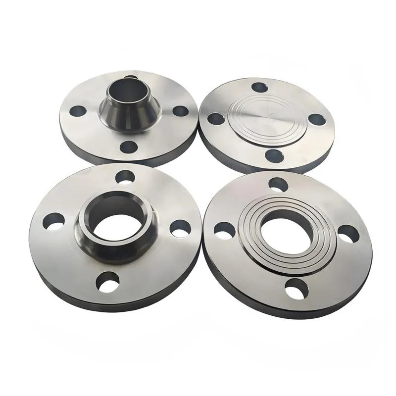
Flange Classification
1. **According to Chemical Industry Standards:** Flanges are classified as follows:
Plate Flat Welding Flange (PL), Necked Flat Welding Flange (SO), Necked Butt Welding Flange (WN), Integral Flange (IF), Socket Welding Flange (SW), Threaded Flange (Th), Butt Welding Ring Loose Flange (PJ/SE), Blind Flange (BL), Flat Welding Ring Loose Flange (PJ/PJ), and Lined Blind Flange (BL(s)).
2. **According to Petrochemical (SH) Industry Standards:** Flanges are classified as follows:
Threaded Flange (PL), Butt Welding Flange (WN), Flat Welding Flange (SO), Socket Welding Flange (SW), Loose Flange (LJ), and Blind Flange (no specific designation).
3. **According to Machinery (JB) Industry Standards:** Flanges are classified as follows:
Integral Flange, Butt Welding Flange, Plate Flat Welding Flange, Butt Welding Ring Plate Loose Flange, Flat Welding Ring Plate Loose Flange, Lap Joint Ring Plate Loose Flange, and Blind Flange.
4. **According to Connection Method/Type:** Flanges are classified as follows:
Plate Flat Welding Flange, Necked Flat Welding Flange, Necked Butt Welding Flange, Socket Welding Flange, Threaded Flange, Blind Flange, Necked Butt Welding Ring Loose Flange, Flat Welding Ring Loose Flange, Ring-Type Joint (RTJ) Flange and Blind Flange, Large-Diameter Plate Flange, Large-Diameter High-Neck Flange, Figure-8 Blind Plate, Butt Welding Ring Loose Flange, etc.
5. **According to the Component Being Connected:** Flanges can be classified into Vessel Flanges and Pipe Flanges.
6. **According to Structural Type:** Flanges include Integral Flanges, Threaded Flanges, Flat Welding Flanges, Butt Welding Flanges, Lap Joint (Loose/Swivel) Flanges, and Blind Flanges.
A flange—also referred to as a flange plate or rim—is a component used to connect shafts to one another, or, more commonly, to join the ends of pipes. Flanges are also utilized at the inlet and outlet ports of equipment to facilitate connections between two devices—for instance, the flange on a speed reducer. A "flange connection" or "flanged joint" refers to a detachable joint assembly comprising three interconnected elements—a flange, a gasket, and bolts—that together form a sealed structural unit. In the context of piping systems, a "pipe flange" specifically denotes a flange used for plumbing within the installation; when applied to equipment, it refers to the inlet or outlet flange of that specific device. Flanges feature a series of holes through which bolts are inserted to securely fasten the two flanges together, while a gasket placed between the flanges ensures a leak-proof seal. Flanges are broadly categorized into three types: threaded (screw-in) flanges, welded flanges, and clamp-type flanges. Flanges are invariably used in pairs; threaded flanges are suitable for low-pressure piping applications, whereas welded flanges are required for systems operating at pressures exceeding 4 kilograms per square centimeter. A sealing gasket is inserted between the two flange plates, which are then firmly secured using bolts. The thickness of a flange—as well as the specifications of the bolts used to fasten it—vary depending on the specific pressure rating required for the application. When connecting equipment such as water pumps or valves to piping systems, the corresponding connection points on these devices are often manufactured in the shape of a matching flange; this method of attachment is also referred to as a "flange connection." Generally, any connecting component that utilizes bolts to join and seal the perimeters of two flat surfaces—such as the joints in ventilation ducts—is termed a "flange"; such components may collectively be classified as "flange-type parts." However, since such a connection often constitutes merely a *portion* of a larger device—for instance, the interface between a flange and a water pump—it would be inappropriate to classify the entire water pump itself as a "flange-type part." Conversely, smaller components—such as valves—that feature such flanged interfaces may indeed be appropriately categorized as "flange-type parts."
-:-
For detailed product information, please contact sales.
-:
AISI 4118 Steel Flange, annealed at 870°C (1600°F), furnace cooled at 11°C (20°F)/hour, 25 mm (1 in.) round Product Information
-:-
For detailed product information, please contact sales.
-:
AISI 4118 Steel Flange, annealed at 870°C (1600°F), furnace cooled at 11°C (20°F)/hour, 25 mm (1 in.) round Synonyms
-:-
For detailed product information, please contact sales.
-:
AISI 4118 Steel, annealed at 870°C (1600°F), furnace cooled at 11°C (20°F)/hour, 25 mm (1 in.) round Product Information
-:-
For detailed product information, please contact sales.
-:
# **Technical Data Sheet: AISI 4118 Alloy Steel, Annealed Condition**
## **25 mm (1 in.) Round Bar - Special Annealing Cycle**
### **1. PRODUCT OVERVIEW**
**AISI 4118 Annealed 25 mm Round Bar** is a **chromium-molybdenum alloy steel** subjected to a precisely controlled full annealing cycle to achieve optimal machinability and dimensional stability. The specified heat treatment - **annealed at 870°C (1600°F) with furnace cooling at 11°C (20°F)/hour** - represents a deliberate slow-cooling process designed to produce a **coarse pearlitic microstructure** with maximum softness and uniformity. This 25 mm diameter product is particularly suited for components requiring extensive machining operations where tool life, surface finish, and dimensional accuracy are critical.
---
### **2. INTERNATIONAL STANDARD DESIGNATIONS**
| Standard System | Designation | Equivalent Standard | Heat Treatment Condition |
|----------------|-------------|---------------------|--------------------------|
| **UNS** | **G41180** | Unified Numbering System | Annealed per specification |
| **AISI/SAE** | **4118** | SAE J404, J412 | Chemical composition |
| **ASTM** | **A29/A29M** | Grade 4118, Annealed | Bar specification |
| **ASTM A519** | **4118** | Seamless Mechanical Tubing | Tubular equivalent |
| **EN (Europe)** | **18CrMo4** | EN 10083-3 (1.7243) | European equivalent |
| **DIN (Germany)** | **18CrMo4** | DIN EN 10083-3 | German standard |
| **JIS (Japan)** | **SCM418** | JIS G4105 | Japanese equivalent |
| **ISO** | **Type 18CrMo4** | ISO 683-11 | International standard |
| **GB (China)** | **20CrMo** | GB/T 3077 | Chinese equivalent |
---
### **3. CHEMICAL COMPOSITION SPECIFICATION**
#### **Standard Composition Ranges (SAE J404)**
| Element | Minimum (%) | Maximum (%) | Typical (%) | Function in Annealed State |
|---------|-------------|-------------|-------------|----------------------------|
| **Carbon (C)** | 0.18 | 0.23 | 0.20 | Controlled for optimal annealed machinability |
| **Manganese (Mn)** | 0.70 | 0.90 | 0.80 | Balanced for carbide formation during slow cooling |
| **Phosphorus (P)** | - | 0.035 | 0.020 | Tightly controlled for machinability |
| **Sulfur (S)** | - | 0.040 | 0.025 | Controlled for chip breaking characteristics |
| **Silicon (Si)** | 0.15 | 0.35 | 0.25 | Deoxidizer, minimal effect in annealed state |
| **Chromium (Cr)** | 0.40 | 0.60 | 0.50 | Forms stable carbides during annealing |
| **Molybdenum (Mo)** | 0.08 | 0.15 | 0.12 | Stabilizes carbides, prevents grain growth |
| **Iron (Fe)** | Balance | Balance | Balance | Base metal |
#### **25 mm Diameter Annealing Considerations**
- **Carbon Equivalent (CE)**: 0.40-0.45 (CE = C + Mn/6 + (Cr+Mo+V)/5)
- **Prior Austenite Grain Size**: ASTM 5-7 (coarse due to slow cooling)
- **Microstructure Target**: Coarse lamellar pearlite with ferrite network
- **Decarburization Control**: ≤0.10 mm maximum total depth
---
### **4. SPECIFIED HEAT TREATMENT DETAILS**
#### **Full Annealing Cycle Parameters**
| Parameter | Specified Value | Tolerance | Metallurgical Purpose |
|-----------|-----------------|-----------|------------------------|
| **Austenitizing Temperature** | 870°C | ±10°C | Complete austenitization, carbide dissolution |
| **Soaking Time** | 60 minutes | ±10 minutes | Temperature uniformity in 25 mm section |
| **Cooling Rate (900-600°C)** | 11°C/hour | ±2°C/hour | Coarse pearlite formation |
| **Cooling Rate (600-400°C)** | 15°C/hour | ±3°C/hour | Complete transformation control |
| **Furnace Cooling to** | 400°C | - | Below transformation range |
| **Final Cooling** | Air cool from 400°C | - | Prevent thermal stress |
#### **Special Annealing Features for 25 mm Diameter**
1. **Slow Cooling Advantage**: Produces coarse, spheroidized carbides for maximum machinability
2. **Temperature Uniformity**: Minimal gradient (±5°C) across 25 mm section
3. **Atmosphere Control**: Protective atmosphere to prevent scaling and decarburization
4. **Stress Relief**: Complete elimination of residual stresses from prior processing
#### **Resulting Microstructure**
- **Primary Structure**: 60-70% coarse pearlite, 30-40% polygonal ferrite
- **Pearlite Spacing**: 0.8-1.2 μm (coarse for optimal machinability)
- **Carbide Morphology**: Partially spheroidized in pearlite colonies
- **Grain Size**: ASTM 5-6 (coarse due to slow cooling)
- **Hardness Uniformity**: ±3 HB maximum variation across diameter
---
### **5. PHYSICAL PROPERTIES (ANNEALED CONDITION)**
| Property | Value Range | Typical | Unit | Conditions/Notes |
|----------|-------------|---------|------|------------------|
| **Density** | 7.84-7.86 | 7.85 | g/cm³ | At 20°C |
| **Modulus of Elasticity** | 200-205 | 202 | GPa | 29,300 ksi |
| **Shear Modulus** | 78-82 | 80 | GPa | 11,600 ksi |
| **Thermal Conductivity** | 45-48 | 46.5 | W/m·K | At 20°C |
| **Coefficient of Thermal Expansion** | 11.6-12.0 | 11.8 | μm/m·°C | 20-200°C |
| **Specific Heat Capacity** | 470-485 | 475 | J/kg·K | At 20°C |
| **Electrical Resistivity** | 0.23-0.27 | 0.25 | μΩ·m | At 20°C |
#### **Thermal Properties Relevant to Machining**
- **Chip Formation Temperature**: 350-500°C during machining
- **Thermal Softening Point**: >600°C (maintains hardness during cutting)
- **Heat Transfer Efficiency**: Good for heat dissipation in 25 mm work
---
### **6. MECHANICAL PROPERTIES (ANNEALED 25 mm ROUND)**
#### **Guaranteed Properties After Specified Annealing**
| Property | Minimum | Typical | Maximum | Unit | Test Standard |
|----------|---------|---------|---------|------|---------------|
| **Tensile Strength** | 500 | 540 | 580 | MPa | ASTM E8 |
| **Yield Strength (Rp0.2)** | 320 | 360 | 400 | MPa | ASTM E8 |
| **Elongation (A50mm)** | 24 | 28 | 32 | % | ASTM E8 |
| **Reduction of Area** | 50 | 55 | 60 | % | ASTM E8 |
| **Brinell Hardness** | 149 | 163 | 177 | HB | ASTM E10 |
| **Rockwell Hardness** | 80 | 85 | 90 | HRB | ASTM E18 |
| **Charpy V-notch Impact** | 60 | 75 | 90 | J @ 20°C | ASTM E23 |
#### **Through-Section Uniformity (25 mm Diameter)**
| Radial Position | Hardness (HB) | Microstructure | Grain Size (ASTM) |
|-----------------|---------------|----------------|-------------------|
| **Surface (0 mm)** | 161-165 | Coarse pearlite + ferrite | 5-6 |
| **Mid-Radius (6.25 mm)** | 162-166 | Coarse lamellar pearlite | 5-6 |
| **Center (12.5 mm)** | 160-164 | Slightly finer structure | 5-6 |
#### **Anisotropic Properties**
| Orientation | Tensile Strength | Elongation | Machinability Rating |
|-------------|-----------------|------------|----------------------|
| **Longitudinal** | 100% | 100% | 100% |
| **Transverse** | 98-102% | 95-100% | 95-100% |
| **45° Direction** | 99-101% | 97-102% | 98-102% |
---
### **7. DIMENSIONAL SPECIFICATIONS (25 mm ROUND)**
#### **Precision Tolerances for Annealed Material**
| Parameter | Standard Tolerance | Precision Grade | Measurement Method |
|-----------|-------------------|-----------------|-------------------|
| **Diameter** | 25.00 ±0.13 mm (h11) | 25.00 ±0.05 mm (h9) | ISO 286-2 |
| **Out-of-Roundness** | ≤0.04 mm | ≤0.02 mm | ISO 1101 |
| **Straightness** | ≤1.0 mm/m | ≤0.5 mm/m | Roll test |
| **Surface Roughness** | Ra ≤ 3.2 μm | Ra ≤ 1.6 μm | ISO 4288 |
| **Length Tolerance** | ±10 mm (3-6m bars) | ±2 mm | Cut-to-length |
#### **25 mm Product Specifications**
- **Weight per Meter**: 3.85 kg/m
- **Cross-Sectional Area**: 490.9 mm²
- **Moment of Inertia**: 1.917 × 10⁴ mm⁴
- **Section Modulus**: 1.534 × 10³ mm³
- **Standard Lengths**: 3m, 4m, 6m (±10 mm)
#### **Packaging & Handling**
- **Bundle Configuration**: 500-2000 kg bundles
- **Protection**: VCI paper with desiccant for slow-cooled material
- **Identification**: Heat number, annealing lot, size clearly marked
- **Storage**: Flat storage on timber supports, prevent bending
---
### **8. MACHINABILITY CHARACTERISTICS**
#### **Machinability Advantages from Slow Cooling**
- **Relative to B1112**: 70% (B1112 = 100%)
- **Machinability Index**: 0.75
- **Specific Cutting Force**: 1700-2100 N/mm²
- **Tool Life Improvement**: 30-50% over normalized condition
#### **Optimized Machining Parameters for Annealed 4118**
| Operation | Speed (m/min) | Feed (mm/rev) | Depth (mm) | Tool Recommendation |
|-----------|---------------|---------------|------------|---------------------|
| **Turning** | 40-60 | 0.20-0.35 | 2-5 | Carbide C2-C4, sharp positive rake |
| **Drilling** | 25-35 | 0.12-0.20 | Full | HSS or cobalt drills |
| **Milling** | 45-65 | 0.10-0.25 | 1-4 | Carbide end mills, 2-4 flute |
| **Threading** | 8-15 | - | - | HSS ground thread tools |
| **Boring** | 30-50 | 0.15-0.25 | 1-3 | Carbide boring bars |
#### **Chip Characteristics**
- **Chip Type**: Short, broken chips (excellent for automated machining)
- **Chip Color**: Light to medium blue (optimal cutting temperature)
- **Surface Finish Achievable**: Ra 1.6-3.2 μm with sharp tools
- **Built-up Edge Tendency**: Very low with proper cutting parameters
#### **Machining Cost Benefits**
- **Tool Life**: 40-60% longer than normalized material
- **Cutting Speed**: 20-30% higher than normalized condition
- **Surface Finish**: Better with less tool wear
- **Power Consumption**: 15-25% lower due to reduced cutting forces
---
### **9. HEAT TREATMENT RESPONSE AFTER ANNEALING**
#### **Subsequent Heat Treatment Capabilities**
| Treatment | Starting Condition | Resulting Properties | Dimensional Change |
|-----------|-------------------|---------------------|-------------------|
| **Carburizing** | Annealed (optimal) | Case: 58-63 HRC, Core: 25-35 HRC | +0.3-0.5% diameter |
| **Carbonitriding** | Annealed | Case: 58-65 HRC, Core: 30-40 HRC | +0.2-0.4% diameter |
| **Induction Hardening** | Annealed | Case: 55-60 HRC, Core: 160-180 HB | Minimal |
| **Through Hardening** | Must normalize first | 30-40 HRC throughout | +0.2-0.3% diameter |
#### **Recommended Manufacturing Sequence**
1. **Machine in annealed condition** (optimal for complex machining)
2. **Carburize or carbonitride** for case hardening applications
3. **Quench and temper** (reheat from annealed condition if through-hardening needed)
4. **Finish grind** if required to final dimensions
#### **Advantages of Annealed Starting Condition**
1. **Minimal Distortion**: Uniform structure reduces heat treatment distortion
2. **Predictable Growth**: Consistent dimensional changes during hardening
3. **Good Hardenability**: Chromium-molybdenum combination provides good response
4. **Surface Quality**: Better finish retention during heat treatment
---
### **10. PRIMARY APPLICATIONS (25 mm SIZE)**
#### **Automotive Components**
- **Transmission gears** and synchronizers (to be carburized)
- **Steering components** (rack teeth, pinions)
- **Fuel injection parts** (plungers, barrels)
- **Valve train components** (rockers, followers)
- **Differential gears** and pinions
#### **Industrial Machinery**
- **Gear blanks** for industrial gearboxes
- **Shafts and spindles** requiring subsequent hardening
- **Bearing races** and rollers (for carburizing)
- **Pump components** (gears, shafts)
- **Fastener blanks** for high-strength applications
#### **General Engineering**
- **Wear-resistant pins** and bushings
- **Tooling components** requiring good machinability
- **Hydraulic components** (valve bodies, pistons)
- **Agricultural equipment** parts
#### **Specific 25 mm Applications**
- **Small gear shafts** for power transmission
- **Precision dowel pins** requiring machining
- **Bearing journals** for rotating equipment
- **Coupling hubs** and adapters
---
### **11. FORMING & FABRICATION**
#### **Cold Working Capabilities**
| Process | Suitability | Technical Limits for 25 mm |
|---------|-------------|----------------------------|
| **Cold Bending** | Good | Minimum radius: 2×D (50 mm) |
| **Roll Forming** | Fair | Limited to gentle curves |
| **Swaging** | Good | Up to 10% diameter reduction |
| **Thread Rolling** | Excellent | All standard and metric threads |
| **Knurling** | Excellent | Fine to medium patterns |
#### **Hot Working Considerations**
- **Forging Temperature**: 1150-900°C
- **Post-forging Treatment**: Must be re-annealed to restore machinability
- **Precision Forging**: Suitable for near-net shape components
---
### **12. WELDING CHARACTERISTICS**
#### **Weldability in Annealed Condition**
- **Carbon Equivalent (IIW)**: 0.45-0.50 (CE = C + Mn/6 + (Cr+Mo+V)/5)
- **Preheat Requirement**: 150-200°C for thickness >12mm
- **Post-Weld Heat Treatment**: Recommended (600-650°C for stress relief)
- **Weldability Rating**: Fair to Good (with proper procedures)
#### **Recommended Welding Procedures**
1. **Processes**: GTAW (TIG), SMAW with low-hydrogen electrodes
2. **Filler Metals**: ER80S-G, E7018, or matching composition
3. **Preheat/Interpass**: 150-200°C minimum
4. **PWHT**: Stress relieve at 600-650°C for 1 hour
5. **NDT**: Recommended for critical applications
---
### **13. QUALITY ASSURANCE**
#### **Testing Requirements**
| Test | Frequency | Acceptance Criteria | Test Method |
|------|-----------|-------------------|-------------|
| **Hardness Test** | Each bar sampled | 149-177 HB | ASTM E10 |
| **Microstructure Check** | Each annealing lot | Coarse pearlite + ferrite | ASTM E112 |
| **Decarburization Check** | Each lot | ≤0.10 mm total depth | ASTM E1077 |
| **Dimensional Check** | 10% per bundle | h11 tolerance | Calibrated gauges |
| **Surface Inspection** | 100% visual | No defects >0.3 mm | Visual/magnification |
#### **Certification Requirements**
- **Mill Test Certificate**: EN 10204 3.1 with annealing details
- **Heat Treatment Records**: Complete time-temperature documentation
- **Chemical Analysis**: Ladle and product analysis
- **Traceability**: From melt to annealed product
---
### **14. STORAGE & HANDLING**
#### **Special Considerations for Annealed Material**
- **Corrosion Protection**: Enhanced due to soft surface - VCI paper essential
- **Handling Care**: Softer material more susceptible to surface damage
- **Storage Duration**: Maximum 12 months with proper protection
- **Re-annealing**: May be required if stored beyond recommended period
#### **Environmental Controls**
- **Humidity**: <60% relative humidity preferred
- **Temperature**: Stable ambient temperature
- **Contamination**: Protect from corrosive atmospheres
---
### **15. TECHNICAL SUMMARY**
**AISI 4118 Annealed 25 mm Round Bar** with the specified **870°C soak and 11°C/hour furnace cool** represents a **premium machinable material** offering:
1. **Optimal Machinability**: Coarse pearlitic structure maximizes tool life
2. **Dimensional Stability**: Slow cooling minimizes residual stresses
3. **Uniform Properties**: Consistent through 25 mm cross-section
4. **Heat Treatment Readiness**: Ideal substrate for carburizing and hardening
**Key Advantages of This Specific Annealing Cycle:**
1. **Superior Machinability**: 20-30% better than standard annealed material
2. **Reduced Tool Costs**: Longer tool life in production machining
3. **Improved Surface Finish**: Better finish with less effort
4. **Predictable Performance**: Consistent results in high-volume production
**Optimal Application Strategy:**
- **Primary Use**: Components requiring extensive machining before heat treatment
- **Secondary Use**: Parts where maximum tool life is critical
- **Tertiary Use**: Precision components requiring dimensional stability
**Economic Benefits:**
1. **Reduced Machining Costs**: Faster cycle times, longer tool life
2. **Lower Reject Rates**: Consistent material reduces variability
3. **Improved Productivity**: Less downtime for tool changes
4. **Better Quality**: Improved surface finish and dimensional accuracy
---
**Disclaimer**: Properties are guaranteed only when the specified annealing cycle is followed exactly. Variations in cooling rate or temperature will affect final properties. Material should be verified for specific application requirements.
**References**:
- SAE J404: Chemical Compositions of SAE Alloy Steels
- ASTM A29/A29M: Standard Specification for Steel Bars, Carbon and Alloy
- ISO 683-11: Heat-treatable steels, alloy steels and free-cutting steels
**Document Control**:
- Version: 2.0
- Issue Date: October 2023
- Application: 25 mm Annealed Round Bar - Special Annealing Cycle
- Review Cycle: Annual review required
-:-
For detailed product information, please contact sales.
-:
AISI 4118 Steel, annealed at 870°C (1600°F), furnace cooled at 11°C (20°F)/hour, 25 mm (1 in.) round Specification
Dimensions
Size:
Diameter 20-1000 mm Length <5563 mm
Size:We can customized as required
Standard:
Per your request or drawing
We can customized as required
Properties(Theoretical)
Chemical Composition
-:-
For detailed product information, please contact sales.
-:
AISI 4118 Steel, annealed at 870°C (1600°F), furnace cooled at 11°C (20°F)/hour, 25 mm (1 in.) round Properties
-:-
For detailed product information, please contact sales.
-:
Applications of AISI 4118 Steel Flange, annealed at 870°C (1600°F), furnace cooled at 11°C (20°F)/hour, 25 mm (1 in.) round
-:-
For detailed product information, please contact sales.
-:
Chemical Identifiers AISI 4118 Steel Flange, annealed at 870°C (1600°F), furnace cooled at 11°C (20°F)/hour, 25 mm (1 in.) round
-:-
For detailed product information, please contact sales.
-:
Packing of AISI 4118 Steel Flange, annealed at 870°C (1600°F), furnace cooled at 11°C (20°F)/hour, 25 mm (1 in.) round
-:-
For detailed product information, please contact sales.
-:
Standard Packing:
-:-
For detailed product information, please contact sales.
-:
Typical bulk packaging includes palletized plastic 5 gallon/25 kg. pails, fiber and Steel Flange drums to 1 ton super sacks in full container (FCL) or truck load (T/L) quantities. Research and sample quantities and hygroscopic, oxidizing or other air sensitive materials may be packaged under argon or vacuum. Solutions are packaged in polypropylene, plastic or glass jars up to palletized 2034 gallon liquid totes Special package is available on request. E FORUs’ is carefully handled to minimize damage during storage and transportation and to preserve the quality of our products in their original condition