1,We Manufacturing processes are primarily classified into four types:
1:Forging,
2:Casting,
3:Cutting,
4:Rolling.
2,We can manufacture in accordance with these standards.
Standards:
GB Series (Chinese Standards), JB Series (Machinery Standards), HG Series (Chemical Industry Standards), ASME B16.5 (American Standards), BS4504 (British Standards), DIN (German Standards), and JIS (Japanese Standards).
Internationally, there are two primary systems of pipe flange standards: the European system, represented by the German DIN standards (including those of the former Soviet Union), and the American system, represented by the US ANSI pipe flange standards. Other common standards include: the Chinese Ministry of Machinery Industry standards (JB series), the Ministry of Chemical Industry standards (HG series), the Chinese National Standard *GB/T 9112–9124-2010 Steel Pipe Flanges*, as well as US standards (ASME B16.5), British standards (BS4504), German standards (DIN), Japanese standards (JIS), and marine standards (CBM), among others.
The nominal pressure ratings for the PN series are designated by "PN" and comprise the following nine levels: PN2.5, PN6, PN10, PN16, PN25, PN40, PN63, PN100, and PN160.
The nominal pressure ratings for the Class series are designated by "Class" and comprise the following six levels: Class150, Class300, Class600, Class900, Class1500, and Class2500.
Flange Classification
1. **According to Chemical Industry Standards:** Flanges are classified as follows:
Plate Flat Welding Flange (PL), Necked Flat Welding Flange (SO), Necked Butt Welding Flange (WN), Integral Flange (IF), Socket Welding Flange (SW), Threaded Flange (Th), Butt Welding Ring Loose Flange (PJ/SE), Blind Flange (BL), Flat Welding Ring Loose Flange (PJ/PJ), and Lined Blind Flange (BL(s)).
2. **According to Petrochemical (SH) Industry Standards:** Flanges are classified as follows:
Threaded Flange (PL), Butt Welding Flange (WN), Flat Welding Flange (SO), Socket Welding Flange (SW), Loose Flange (LJ), and Blind Flange (no specific designation).
3. **According to Machinery (JB) Industry Standards:** Flanges are classified as follows:
Integral Flange, Butt Welding Flange, Plate Flat Welding Flange, Butt Welding Ring Plate Loose Flange, Flat Welding Ring Plate Loose Flange, Lap Joint Ring Plate Loose Flange, and Blind Flange.
4. **According to Connection Method/Type:** Flanges are classified as follows:
Plate Flat Welding Flange, Necked Flat Welding Flange, Necked Butt Welding Flange, Socket Welding Flange, Threaded Flange, Blind Flange, Necked Butt Welding Ring Loose Flange, Flat Welding Ring Loose Flange, Ring-Type Joint (RTJ) Flange and Blind Flange, Large-Diameter Plate Flange, Large-Diameter High-Neck Flange, Figure-8 Blind Plate, Butt Welding Ring Loose Flange, etc.
5. **According to the Component Being Connected:** Flanges can be classified into Vessel Flanges and Pipe Flanges.
6. **According to Structural Type:** Flanges include Integral Flanges, Threaded Flanges, Flat Welding Flanges, Butt Welding Flanges, Lap Joint (Loose/Swivel) Flanges, and Blind Flanges.
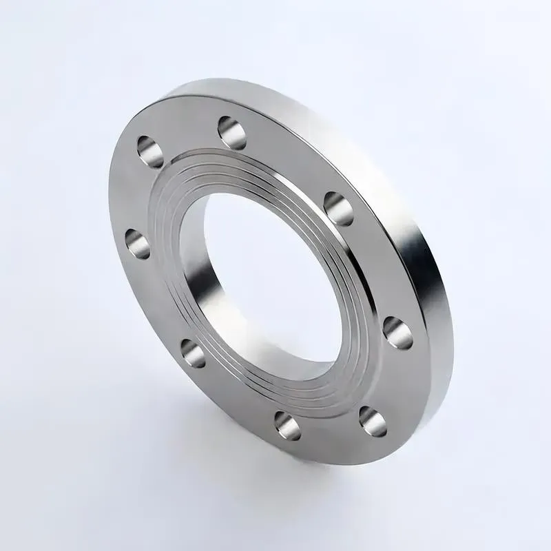
A flange—also referred to as a flange plate or rim—is a component used to connect shafts to one another, or, more commonly, to join the ends of pipes. Flanges are also utilized at the inlet and outlet ports of equipment to facilitate connections between two devices—for instance, the flange on a speed reducer. A "flange connection" or "flanged joint" refers to a detachable joint assembly comprising three interconnected elements—a flange, a gasket, and bolts—that together form a sealed structural unit. In the context of piping systems, a "pipe flange" specifically denotes a flange used for plumbing within the installation; when applied to equipment, it refers to the inlet or outlet flange of that specific device. Flanges feature a series of holes through which bolts are inserted to securely fasten the two flanges together, while a gasket placed between the flanges ensures a leak-proof seal. Flanges are broadly categorized into three types: threaded (screw-in) flanges, welded flanges, and clamp-type flanges. Flanges are invariably used in pairs; threaded flanges are suitable for low-pressure piping applications, whereas welded flanges are required for systems operating at pressures exceeding 4 kilograms per square centimeter. A sealing gasket is inserted between the two flange plates, which are then firmly secured using bolts. The thickness of a flange—as well as the specifications of the bolts used to fasten it—vary depending on the specific pressure rating required for the application. When connecting equipment such as water pumps or valves to piping systems, the corresponding connection points on these devices are often manufactured in the shape of a matching flange; this method of attachment is also referred to as a "flange connection." Generally, any connecting component that utilizes bolts to join and seal the perimeters of two flat surfaces—such as the joints in ventilation ducts—is termed a "flange"; such components may collectively be classified as "flange-type parts." However, since such a connection often constitutes merely a *portion* of a larger device—for instance, the interface between a flange and a water pump—it would be inappropriate to classify the entire water pump itself as a "flange-type part." Conversely, smaller components—such as valves—that feature such flanged interfaces may indeed be appropriately categorized as "flange-type parts."
-:-
For detailed product information, please contact sales.
-:
AISI 4145H Steel Flange Product Information
-:-
For detailed product information, please contact sales.
-:
AISI 4145H Steel Flange Synonyms
-:-
For detailed product information, please contact sales.
-:
AISI 4145H Steel Product Information
-:-
For detailed product information, please contact sales.
-:
# **AISI 4145H Steel - Hardenability Controlled Alloy Steel Product Specification**
## **1. Product Overview & "H" Designation Significance**
**AISI 4145H** is a medium-high carbon chromium-molybdenum alloy steel supplied under the **"H" designation**, which indicates it is manufactured to meet specific hardenability band requirements as defined by ASTM standards. This designation represents a fundamental shift in quality philosophy: rather than guaranteeing fixed chemical composition percentages, 4145H guarantees consistent hardenability response regardless of production lot variations. This makes it the preferred choice for large, safety-critical components where predictable heat treatment results are essential.
**Key Distinction:** *The "H" in 4145H stands for guaranteed hardenability, not just higher carbon content.*
## **2. International Standards & Designations**
| Region/Standard | Designation | Governing Standard |
|-----------------|-------------|---------------------|
| **United States** | AISI 4145H, UNS H41450 | ASTM A304 (Primary), ASTM A914 |
| **Europe** | 1.7228H (42CrMo5H) | EN 10083-3 with H-band requirements |
| **Japan** | SCM445H | JIS G4052 |
| **China** | 42CrMoH (Modified) | GB/T 5216 |
| **International** | 42CrMo5 with H-band | ISO 683-18 |
| **Aerospace** | - | AMS 6347 (similar but not H-grade) |
**Critical Standard:** **ASTM A304** - Standard Specification for Carbon and Alloy Steel Bars Subject to End-Quench Hardenability Requirements
## **3. Chemical Composition (Weight % - H-Steel Philosophy)**
*H-steels allow controlled chemistry variation to achieve guaranteed hardenability bands*
| Element | ASTM A304 Range (%) | Typical Aim (%) | H-Steel Philosophy |
|---------|----------------------|-----------------|-------------------|
| **Carbon (C)** | 0.42 - 0.49 | 0.45 | May vary between heats to maintain hardenability band |
| **Manganese (Mn)** | 0.70 - 1.00 | 0.85 | Wider range than standard 4145 for hardenability tuning |
| **Phosphorus (P)** | ≤ 0.030 | 0.020 | Lower maximum than standard grade for improved toughness |
| **Sulfur (S)** | ≤ 0.030 | 0.020 | Controlled for consistent machinability across heats |
| **Silicon (Si)** | 0.15 - 0.35 | 0.25 | Standard range maintained |
| **Chromium (Cr)** | 0.75 - 1.10 | 0.95 | Slightly wider lower limit for manufacturing flexibility |
| **Molybdenum (Mo)** | 0.15 - 0.25 | 0.20 | Critical for temper embrittlement resistance |
| **Boron (B)*** | 0.0005 - 0.003 | Optional | Added to some heats for enhanced hardenability efficiency |
**H-Steel Manufacturing Philosophy:**
- **Lot A:** C=0.43%, Mn=0.90%, Cr=0.85%
- **Lot B:** C=0.47%, Mn=0.75%, Cr=1.05%
- **Result:** Both lots exhibit **identical hardenability** within specified band despite different chemistries
## **4. Hardenability Characteristics - The Defining Feature**
### **Jominy End-Quench Test Requirements (ASTM A304)**
*4145H is typically supplied to specific hardenability bands (e.g., Band 3, 4, or 5)*
| Distance from Quenched End | Hardness Range, HRC (Band 4 Typical) | Hardness Range, HRC (Band 5 Typical) |
|----------------------------|--------------------------------------|--------------------------------------|
| **J₁ (1/16")** | 56 - 62 | 58 - 64 |
| **J₄ (4/16")** | 51 - 58 | 53 - 60 |
| **J₈ (8/16")** | 44 - 52 | 46 - 54 |
| **J₁₂ (12/16")** | 38 - 46 | 40 - 48 |
| **J₁₆ (16/16")** | 33 - 41 | 35 - 43 |
| **J₂₀ (20/16")** | 30 - 38 | 32 - 40 |
| **J₂₈ (28/16")** | 26 - 34 | 28 - 36 |
### **Hardenability Performance Metrics**
| Parameter | Value Range | Significance |
|-----------|-------------|--------------|
| **Ideal Critical Diameter (Dᵢ)** | 3.8 - 4.5 inches (97 - 114 mm) | Maximum diameter for 50% martensite at center in ideal quench |
| **95% Martensite Diameter (D₉₅)** | 3.0 - 3.8 inches (76 - 97 mm) | Practical maximum for full hardening in oil |
| **Grossmann Hardenability Factor** | 5.5 - 6.5 | Excellent hardenability rating |
| **Quench Severity (H-value)** | 0.35 - 0.50 (oil) | Moderate to good quench severity required |
## **5. Physical Properties**
*Properties are similar to standard 4145 but with better consistency*
| Property | Value | Conditions/Notes |
|----------|-------|------------------|
| **Density** | 7.85 g/cm³ (0.284 lb/in³) | At 20°C |
| **Melting Range** | 1400 - 1510°C (2550 - 2750°F) | Slightly wider due to chemistry variations |
| **Modulus of Elasticity (E)** | 205 GPa (29.7 × 10⁶ psi) | Consistent across all heats |
| **Shear Modulus (G)** | 80 GPa (11.6 × 10⁶ psi) | - |
| **Poisson's Ratio (ν)** | 0.29 | - |
| **Thermal Conductivity** | 40.5 - 41.5 W/m·K | At 100°C, varies with heat treatment |
| **Specific Heat Capacity** | 460 - 475 J/kg·K | At 20°C |
| **Coefficient of Thermal Expansion** | 12.0 × 10⁻⁶ /K | 20-100°C range |
| **Electrical Resistivity** | 0.24 - 0.26 µΩ·m | At 20°C, depends on microstructure |
| **Magnetic Properties** | Ferromagnetic | Strongly magnetic in all conditions |
## **6. Mechanical Properties by Condition**
### **As-Supplied Conditions (Typical)**
| Condition | Hardness Range | Tensile Strength | Yield Strength | Primary Use |
|-----------|---------------|------------------|----------------|-------------|
| **Annealed** | 197 - 229 HB | 655 - 795 MPa | 415 - 550 MPa | Machining stock |
| **Normalized** | 217 - 255 HB | 725 - 860 MPa | 480 - 620 MPa | Forging blanks |
| **Hot-Rolled** | 229 - 269 HB | 795 - 930 MPa | 550 - 690 MPa | General purpose |
### **Quenched & Tempered Properties (Guaranteed Minimums)**
*Based on proper heat treatment of material within hardenability band*
| Target Hardness | Tensile Strength Range | Yield Strength Range | Impact Energy (20°C) | Reliability Factor* |
|-----------------|------------------------|----------------------|----------------------|---------------------|
| **340 HB (36 HRC)** | 1170 - 1310 MPa | 1035 - 1170 MPa | 54 - 81 J | 0.95 |
| **380 HB (40 HRC)** | 1310 - 1450 MPa | 1170 - 1310 MPa | 41 - 68 J | 0.98 |
| **420 HB (44 HRC)** | 1450 - 1590 MPa | 1310 - 1450 MPa | 27 - 54 J | 0.99 |
| **460 HB (48 HRC)** | 1590 - 1725 MPa | 1450 - 1590 MPa | 14 - 41 J | 0.97 |
***Reliability Factor:** Probability of achieving minimum specified properties across multiple heats (unique to H-steels)*
## **7. Heat Treatment Guidelines for 4145H**
### **Standard Heat Treatment Parameters**
```
HEATING RATE: Slow to 650°C (1200°F), then moderate to austenitizing temperature
PREHEAT: 650-700°C (1200-1290°F) for 30 min/inch (mandatory for sections >50 mm)
AUSTENITIZE: 845-870°C (1550-1600°F) for 30 min/inch minimum
QUENCH MEDIUM: Oil, 40-70°C (100-160°F), agitated
TEMPER: According to desired hardness (see tempering chart)
TEMPERING TIME: 1-2 hours/inch, minimum 2 hours for any thickness
COOLING: Air cool; water quench through 375-575°C range to avoid temper embrittlement
```
### **H-Steel Specific Advantages in Heat Treatment**
1. **Predictable Results:** Identical time-temperature parameters produce identical results across heats
2. **Reduced Scrap:** Minimal heat treatment trial runs required
3. **Optimized Processes:** Can fine-tune processes for specific hardness ranges
4. **Consistent Distortion:** Predictable dimensional changes during heat treatment
### **Tempering Response Curve for 4145H**
```
Tempering Temperature vs. Hardness (Typical):
200°C (400°F) → 52-56 HRC
315°C (600°F) → 48-52 HRC
425°C (800°F) → 42-46 HRC
540°C (1000°F) → 36-40 HRC
595°C (1100°F) → 32-36 HRC
650°C (1200°F) → 28-32 HRC
```
## **8. Product Applications - Where 4145H Excels**
### **Oil & Gas - Critical Drilling Components**
- **Drill collars** (API Spec 7-1, 7-2) - 4-8 inch diameters requiring uniform hardening
- **Heavy-weight drill pipe** - consistent properties over entire length
- **Tool joints** and **connections** - where thread integrity depends on uniform hardness
- **Kelly bars** - large rectangular sections needing predictable heat treatment
- **BOP (Blowout Preventer) rams** and **components** - safety-critical applications
### **Power Generation - Large Rotating Equipment**
- **Turbine shafts** (non-nuclear auxiliary systems)
- **Generator rotor shafts** - where uniform properties prevent imbalance
- **Coupling hubs** and **flanges** - large diameters with bolt circles
- **Valve stems** for high-pressure steam service
- **Pump shafts** for boiler feed applications
### **Heavy Equipment & Mining**
- **Final drive gears** for 200+ ton mining trucks
- **Crawler track links** and **rollers** - large sections with wear requirements
- **Crusher main shafts** - 150-300 mm diameters requiring uniform strength
- **Dragline boom pins** - critical load-bearing components
- **Shovel dipper teeth** and **adapters** - impact and abrasion resistance
### **Marine & Offshore**
- **Propeller shafts** for large vessels
- **Stem tubes** and **bearings**
- **Offshore crane sheave pins** - large diameters with fatigue loading
- **Mooring system components**
- **Drilling riser connectors**
### **Aerospace & Defense (Secondary Structures)**
- **Landing gear components** for heavy aircraft
- **Missile launch rail components**
- **Armor vehicle suspension components**
- **Helicopter rotor hubs** (non-critical applications)
- **Weapon system mounts** and **platforms**
## **9. Manufacturing & Processing Characteristics**
### **Machinability in Various Conditions**
| Condition | Relative Rating | Key Considerations |
|-----------|----------------|-------------------|
| **Annealed (200 HB)** | 65% | Best condition for heavy machining |
| **Pre-hardened (300 HB)** | 45% | Requires carbide tools, rigid setups |
| **Hardened (400+ HB)** | 25% | Grinding preferred, EDM possible |
| **H-Steel Advantage** | More consistent tool life across material lots | |
### **Welding Considerations**
- **Rating:** Very Poor (not recommended in heat-treated condition)
- **If Welding Required:** Must be in annealed condition, then re-heat treated
- **Preheat:** 315-425°C (600-800°F) if welding unavoidable
- **Post-Weld:** Full re-heat treatment cycle required
- **Filler Metals:** AWS E11018-D2 or equivalent
### **Grindability**
- **Rating:** Good with proper techniques
- **Wheel Selection:** Aluminum oxide (A46-J8-V) or CBN for hardened material
- **Coolant:** Essential to prevent grinding burns
- **H-Steel Advantage:** Consistent grinding response across batches
## **10. Quality Assurance & Certification - H-Steel Requirements**
### **Mandatory Testing (Per ASTM A304)**
1. **Jominy End-Quench Test:** One test per heat, certified curve provided
2. **Chemical Analysis:** Full spectrographic analysis
3. **Hardness Verification:** At multiple points to confirm band compliance
4. **Grain Size:** ASTM 5 or finer (fine grain practice)
5. **Macroetch Test:** For internal soundness
### **Optional Enhanced Testing**
- **Ultrasonic Testing:** Per ASTM A388 for critical applications
- **Magnetic Particle Inspection:** Per ASTM A275/A966
- **Charpy Impact Testing:** At multiple temperatures if specified
- **Fracture Toughness Testing:** K₁c testing for critical applications
- **Residual Stress Analysis:** X-ray diffraction if distortion control is critical
### **Certification Documents**
- **ASTM A304 Certificate of Compliance**
- **Jominy Hardenability Curve** (actual test results)
- **Chemical Analysis Report**
- **Heat Treatment Response Data** (if pre-tested by mill)
- **Traceability Documentation** (heat number to finished product)
## **11. Comparison: 4145H vs. Standard 4145**
| Parameter | AISI 4145H | Standard AISI 4145 | Advantage |
|-----------|------------|--------------------|-----------|
| **Hardenability Guarantee** | Yes (Jominy band) | No (chemistry only) | Predictable heat treatment |
| **Chemistry Control** | Wide ranges for H-band | Narrow fixed ranges | Manufacturing flexibility |
| **Lot-to-Lot Consistency** | Excellent | Variable | Reduced scrap, consistent quality |
| **Heat Treatment Results** | Identical across heats | May vary | No process adjustments needed |
| **Large Section Performance** | Guaranteed uniform hardness | May show center softening | Reliable large components |
| **Certification** | Jominy test included | Standard MTR only | Higher confidence level |
| **Cost Premium** | 10-20% | Base cost | Justified by reduced risk |
## **12. Design Guidelines for 4145H**
### **Optimal Application Parameters**
- **Minimum Diameter:** 25 mm (1 inch) - smaller sizes don't benefit from H-grade
- **Optimal Diameter Range:** 50-150 mm (2-6 inches)
- **Maximum Practical Diameter:** 200 mm (8 inches) for full hardening
- **Section Shape:** Rounds optimal; squares/rectangles with aspect ratio <2:1
- **Complexity:** Best for relatively simple shapes; complex geometries may still distort
### **Design Considerations**
1. **Fillets:** Minimum R3 mm (0.125") on all internal corners
2. **Section Transitions:** Gradual changes (taper ≥1:3)
3. **Holes/Features:** Place >2× diameter from edges
4. **Surface Finish:** Critical areas ≤1.6 µm Ra before heat treatment
5. **Dimensional Allowances:** 0.5-1.0 mm per side for grinding after heat treatment
## **13. Available Product Forms & Specifications**
| Product Form | Standard Sizes | Tolerances | Typical Conditions |
|--------------|---------------|------------|-------------------|
| **Round Bars** | 25-300 mm diameter | ±0.5% or ±0.5 mm | Hot-rolled, annealed, rough turned |
| **Forged Bars** | 100-500 mm diameter | ±1% | Annealed or normalized |
| **Billets** | 150²-400² mm | ±2% | As-forged, surface conditioned |
| **Rough Machined** | Per drawing | ±0.2 mm | Annealed, near-net shape |
| **Seamless Tubing** | 50-250 mm OD | Per ASTM A519 | Normalized and tempered |
## **14. Economic & Supply Considerations**
### **Cost Factors**
- **Base Material Cost:** 1.4-1.6 × standard 4145
- **Minimum Order Quantity:** Typically 5,000-10,000 lbs for certified heats
- **Lead Time:** 10-16 weeks for certified material
- **Availability:** Special order from integrated mills (not typically stock items)
- **Global Sources:** USA, Germany, Japan, Korea, limited China production
### **Total Cost of Ownership Considerations**
1. **Reduced Scrap:** Lower heat treatment rejection rates
2. **Process Optimization:** Reduced heat treatment development time
3. **Quality Assurance:** Lower inspection costs due to consistency
4. **Warranty/Risk:** Reduced failure risk in critical applications
5. **Justification:** Easily justified for components with high failure costs
## **15. Technical Appendix: Hardenability Band Selection Guide**
### **Selecting the Appropriate H-Band**
| Application Requirement | Recommended Band | Rationale |
|------------------------|-----------------|-----------|
| **Maximum Toughness** | Lower band (e.g., Band 3) | Lower hardness at J₂₀ indicates better core toughness |
| **Maximum Wear Resistance** | Higher band (e.g., Band 5) | Higher hardness throughout section |
| **Large Diameters (>100 mm)** | Upper half of specified band | Ensures adequate center hardness |
| **Complex Shapes** | Middle of band | Balanced properties minimize distortion |
| **High Fatigue Loading** | Narrower band if available | More consistent properties improve fatigue life |
### **Heat Treatment Process Capability Analysis**
For 4145H, the process capability index (Cpk) for hardness is typically:
- **Surface Hardness:** Cpk ≥ 1.67 (Six Sigma capable)
- **Core Hardness:** Cpk ≥ 1.33 (capable with control)
- **Uniformity (ΔHRC):** Cpk ≥ 1.0 (requires monitoring)
---
## **Summary: When to Specify AISI 4145H**
**Specify 4145H when ANY of these conditions apply:**
1. Component diameter exceeds 50 mm (2 inches)
2. Failure would have safety, environmental, or major economic consequences
3. Production involves multiple heat treat batches over time
4. Component will be used in regulated industries (oil/gas, power, aerospace)
5. Heat treatment distortion control is critical to function
6. The component is part of a high-volume production requiring consistent quality
**Consider standard 4145 when:**
1. Components are small (<25 mm) and non-critical
2. Single heat treat batch for entire production run
3. Cost is primary driver and risk tolerance is high
4. Adequate testing can verify properties post-heat treatment
5. Application is non-regulated with low consequence of failure
---
**Final Note:** AISI 4145H represents the intersection of metallurgical science and quality engineering. It embodies the principle that **performance consistency is more valuable than compositional consistency** for many critical engineering applications. The premium paid for 4145H is essentially insurance against heat treatment variability - insurance that is well-justified for components where failure is not an option.
**Disclaimer:** This product specification is for technical reference only. For critical applications, always consult current ASTM standards, review actual Jominy certification curves, and engage qualified metallurgical engineering support. Properties may vary based on specific manufacturing processes and heat treatment parameters. Always verify material certifications and conduct appropriate qualification testing for safety-critical applications.
-:-
For detailed product information, please contact sales.
-:
AISI 4145H Steel Specification
Dimensions
Size:
Diameter 20-1000 mm Length <4045 mm
Size:We can customized as required
Standard:
Per your request or drawing
We can customized as required
Properties(Theoretical)
Chemical Composition
-:-
For detailed product information, please contact sales.
-:
AISI 4145H Steel Properties
-:-
For detailed product information, please contact sales.
-:
Applications of AISI 4145H Steel Flange
-:-
For detailed product information, please contact sales.
-:
Chemical Identifiers AISI 4145H Steel Flange
-:-
For detailed product information, please contact sales.
-:
Packing of AISI 4145H Steel Flange
-:-
For detailed product information, please contact sales.
-:
Standard Packing:
-:-
For detailed product information, please contact sales.
-:
Typical bulk packaging includes palletized plastic 5 gallon/25 kg. pails, fiber and Steel Flange drums to 1 ton super sacks in full container (FCL) or truck load (T/L) quantities. Research and sample quantities and hygroscopic, oxidizing or other air sensitive materials may be packaged under argon or vacuum. Solutions are packaged in polypropylene, plastic or glass jars up to palletized 516 gallon liquid totes Special package is available on request. E FORUs’ is carefully handled to minimize damage during storage and transportation and to preserve the quality of our products in their original condition