1,We Manufacturing processes are primarily classified into four types:
1:Forging,
2:Casting,
3:Cutting,
4:Rolling.
2,We can manufacture in accordance with these standards.
Standards:
GB Series (Chinese Standards), JB Series (Machinery Standards), HG Series (Chemical Industry Standards), ASME B16.5 (American Standards), BS4504 (British Standards), DIN (German Standards), and JIS (Japanese Standards).
Internationally, there are two primary systems of pipe flange standards: the European system, represented by the German DIN standards (including those of the former Soviet Union), and the American system, represented by the US ANSI pipe flange standards. Other common standards include: the Chinese Ministry of Machinery Industry standards (JB series), the Ministry of Chemical Industry standards (HG series), the Chinese National Standard *GB/T 9112–9124-2010 Steel Pipe Flanges*, as well as US standards (ASME B16.5), British standards (BS4504), German standards (DIN), Japanese standards (JIS), and marine standards (CBM), among others.
The nominal pressure ratings for the PN series are designated by "PN" and comprise the following nine levels: PN2.5, PN6, PN10, PN16, PN25, PN40, PN63, PN100, and PN160.
The nominal pressure ratings for the Class series are designated by "Class" and comprise the following six levels: Class150, Class300, Class600, Class900, Class1500, and Class2500.
Flange Classification
1. **According to Chemical Industry Standards:** Flanges are classified as follows:
Plate Flat Welding Flange (PL), Necked Flat Welding Flange (SO), Necked Butt Welding Flange (WN), Integral Flange (IF), Socket Welding Flange (SW), Threaded Flange (Th), Butt Welding Ring Loose Flange (PJ/SE), Blind Flange (BL), Flat Welding Ring Loose Flange (PJ/PJ), and Lined Blind Flange (BL(s)).
2. **According to Petrochemical (SH) Industry Standards:** Flanges are classified as follows:
Threaded Flange (PL), Butt Welding Flange (WN), Flat Welding Flange (SO), Socket Welding Flange (SW), Loose Flange (LJ), and Blind Flange (no specific designation).
3. **According to Machinery (JB) Industry Standards:** Flanges are classified as follows:
Integral Flange, Butt Welding Flange, Plate Flat Welding Flange, Butt Welding Ring Plate Loose Flange, Flat Welding Ring Plate Loose Flange, Lap Joint Ring Plate Loose Flange, and Blind Flange.
4. **According to Connection Method/Type:** Flanges are classified as follows:
Plate Flat Welding Flange, Necked Flat Welding Flange, Necked Butt Welding Flange, Socket Welding Flange, Threaded Flange, Blind Flange, Necked Butt Welding Ring Loose Flange, Flat Welding Ring Loose Flange, Ring-Type Joint (RTJ) Flange and Blind Flange, Large-Diameter Plate Flange, Large-Diameter High-Neck Flange, Figure-8 Blind Plate, Butt Welding Ring Loose Flange, etc.
5. **According to the Component Being Connected:** Flanges can be classified into Vessel Flanges and Pipe Flanges.
6. **According to Structural Type:** Flanges include Integral Flanges, Threaded Flanges, Flat Welding Flanges, Butt Welding Flanges, Lap Joint (Loose/Swivel) Flanges, and Blind Flanges.
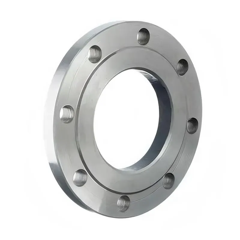
A flange—also referred to as a flange plate or rim—is a component used to connect shafts to one another, or, more commonly, to join the ends of pipes. Flanges are also utilized at the inlet and outlet ports of equipment to facilitate connections between two devices—for instance, the flange on a speed reducer. A "flange connection" or "flanged joint" refers to a detachable joint assembly comprising three interconnected elements—a flange, a gasket, and bolts—that together form a sealed structural unit. In the context of piping systems, a "pipe flange" specifically denotes a flange used for plumbing within the installation; when applied to equipment, it refers to the inlet or outlet flange of that specific device. Flanges feature a series of holes through which bolts are inserted to securely fasten the two flanges together, while a gasket placed between the flanges ensures a leak-proof seal. Flanges are broadly categorized into three types: threaded (screw-in) flanges, welded flanges, and clamp-type flanges. Flanges are invariably used in pairs; threaded flanges are suitable for low-pressure piping applications, whereas welded flanges are required for systems operating at pressures exceeding 4 kilograms per square centimeter. A sealing gasket is inserted between the two flange plates, which are then firmly secured using bolts. The thickness of a flange—as well as the specifications of the bolts used to fasten it—vary depending on the specific pressure rating required for the application. When connecting equipment such as water pumps or valves to piping systems, the corresponding connection points on these devices are often manufactured in the shape of a matching flange; this method of attachment is also referred to as a "flange connection." Generally, any connecting component that utilizes bolts to join and seal the perimeters of two flat surfaces—such as the joints in ventilation ducts—is termed a "flange"; such components may collectively be classified as "flange-type parts." However, since such a connection often constitutes merely a *portion* of a larger device—for instance, the interface between a flange and a water pump—it would be inappropriate to classify the entire water pump itself as a "flange-type part." Conversely, smaller components—such as valves—that feature such flanged interfaces may indeed be appropriately categorized as "flange-type parts."
-:-
For detailed product information, please contact sales.
-:
AISI 4720 Steel Flange Product Information
-:-
For detailed product information, please contact sales.
-:
AISI 4720 Steel Flange Synonyms
-:-
For detailed product information, please contact sales.
-:
AISI 4720 Steel Product Information
-:-
For detailed product information, please contact sales.
-:
# **AISI 4720 Alloy Steel (UNS G47200)**
## **Medium Carbon Nickel-Chromium-Molybdenum Case-Hardening Steel**
---
### **1. PRODUCT OVERVIEW**
**AISI 4720 Alloy Steel (UNS G47200)**
- **Material Classification:** Medium carbon nickel-chromium-molybdenum alloy steel
- **Primary Application:** Case hardening (carburizing or carbonitriding)
- **Carbon Content:** 0.18-0.23% (optimal for case hardening)
- **Key Alloying Elements:** Nickel (0.90-1.20%) + Chromium (0.35-0.55%) + Molybdenum (0.15-0.25%)
- **Material Family:** AISI/SAE 47xx series (nickel-chromium-molybdenum steels)
- **"20" Designation:** Nominal carbon content of 0.20%
- **UNS Designation:** G47200 (Standard), H47200 (Hardenability controlled)
- **Typical Forms:** Rounds, flats, squares, forgings, billets, tubing
**Material Characteristics:**
1. **Balanced Carbon Content:** Optimized for deep case formation without excessive core brittleness
2. **Triple Alloy System:** Nickel for toughness, chromium for hardenability, molybdenum for grain refinement
3. **Excellent Core Properties:** High core strength and toughness after case hardening
4. **Superior Fatigue Resistance:** Ideal for heavily loaded, fatigue-critical components
5. **Good Machinability:** In annealed condition for pre-hardening processing
---
### **2. CHEMICAL COMPOSITION SPECIFICATION**
| Element | AISI 4720 Standard Range (%) | Typical Aim Composition (%) | Metallurgical Function |
|---------|-----------------------------|-----------------------------|------------------------|
| **Carbon (C)** | 0.18-0.23 | 0.19-0.21 | Base strength, carburizing response control |
| **Manganese (Mn)** | 0.50-0.70 | 0.55-0.65 | Enhances hardenability, deoxidation |
| **Phosphorus (P)** | ≤ 0.035 | ≤ 0.020 | Residual impurity (controlled) |
| **Sulfur (S)** | ≤ 0.040 | 0.020-0.035 | Machinability enhancer (controlled levels) |
| **Silicon (Si)** | 0.15-0.30 | 0.20-0.25 | Deoxidizer, solid solution strengthening |
| **Nickel (Ni)** | 0.90-1.20 | 1.00-1.10 | **Primary alloy:** Provides exceptional core toughness |
| **Chromium (Cr)** | 0.35-0.55 | 0.40-0.50 | **Secondary alloy:** Increases hardenability and wear resistance |
| **Molybdenum (Mo)** | 0.15-0.25 | 0.18-0.22 | **Tertiary alloy:** Grain refinement, prevents temper embrittlement |
| **Copper (Cu)** | - | ≤ 0.35 | Trace residual |
| **Aluminum (Al)** | - | 0.020-0.040 | Grain size control (typically added) |
| **Iron (Fe)** | Balance | Balance | Matrix element |
**Composition Design Philosophy:**
- **Carbon Optimization:** 0.20% nominal allows deep, controlled case formation
- **Nickel Content:** 1.0% nominal provides excellent impact resistance in core
- **Chromium Addition:** 0.45% nominal enhances hardenability and wear properties
- **Molybdenum Inclusion:** 0.20% nominal ensures fine grain structure
- **Balanced Design:** Provides better properties than single or dual alloy systems at moderate cost
---
### **3. INTERNATIONAL STANDARDS & EQUIVALENTS**
| Standard System | Designation | Title / Description | Notes |
|----------------|-------------|---------------------|-------|
| **UNS** | G47200 | Unified Numbering System | Primary US designation |
| **AISI/SAE** | 4720 | SAE J404, J412 | Original specification |
| **ASTM** | A322 | Standard Specification for Steel Bars, Alloy | Grade 4720 |
| **ASTM** | A29/A29M | Steel Bars, Carbon and Alloy | General requirements |
| **ASTM** | A534 | Carburizing Steels for Anti-Friction Bearings | Bearing quality |
| **AMS** | 6271 | Steel Bars and Forgings | Aerospace specification |
| **ISO** | 683-11 | Heat-treatable steels | 20NiCrMo2-2 equivalent |
| **DIN** | 1.6523 | 20NiCrMo2-2 | German equivalent |
| **EN** | 1.6523 | 20NiCrMo2-2 | European designation |
| **JIS** | SNCM220 | Nickel-chromium-molybdenum steel | Japanese similar grade |
| **GB** | 20NiCrMo | Chinese standard | Chinese equivalent |
**H-Grade Availability:**
- **AISI 4720H:** Hardenability controlled version
- **Complies with:** SAE J1268 and ASTM A304
- **Typical bands:** Bands 2-4 depending on application requirements
- **Special versions:** 4720HH for extra hardenability control
---
### **4. PHYSICAL PROPERTIES**
| Property | Value | Conditions / Notes |
|----------|-------|-------------------|
| **Density** | 7.85 g/cm³ (0.284 lb/in³) | At 20°C |
| **Melting Range** | 1480-1520°C | Liquidus to solidus temperature |
| **Thermal Conductivity** | 42.5 W/m·K | At 100°C, annealed condition |
| **Specific Heat Capacity** | 460 J/kg·K | At 20°C |
| **Coefficient of Thermal Expansion** | 12.3 × 10⁻⁶/K | 20-100°C temperature range |
| **Electrical Resistivity** | 0.22 μΩ·m | At 20°C |
| **Modulus of Elasticity** | 205 GPa (29.7×10⁶ psi) | Typical for steel |
| **Shear Modulus** | 80 GPa (11.6×10⁶ psi) | - |
| **Poisson's Ratio** | 0.29 | Standard value for steel |
| **Magnetic Properties** | Ferromagnetic | Below Curie temperature (~770°C) |
**Transformation Temperatures:**
- **Ac₁:** ~735°C (1355°F)
- **Ac₃:** ~805°C (1480°F)
- **Ms (Martensite Start):** ~380°C (715°F) for core composition
- **Mf (Martensite Finish):** ~220°C (430°F) for core composition
- **Case Ms:** ~180°C (355°F) for carburized surface
---
### **5. MECHANICAL PROPERTIES**
#### **As-Annealed Properties (For Machining):**
| Property | Value Range | Testing Standard | Application Significance |
|----------|-------------|------------------|--------------------------|
| **Hardness** | 149-197 HB (85-93 HRB) | ASTM E10 | Optimized for machinability |
| **Tensile Strength** | 500-650 MPa (73-94 ksi) | ASTM E8/E8M | Adequate for handling and fixturing |
| **Yield Strength (0.2%)** | 350-450 MPa (51-65 ksi) | ASTM E8/E8M | Sufficient for pre-hardening assembly |
| **Elongation in 4D** | 25-30% | ASTM E8/E8M | Excellent ductility for forming |
| **Reduction of Area** | 50-60% | ASTM E8/E8M | High energy absorption capacity |
| **Machinability Rating** | 65-70% of B1112 steel | Comparative | Good machinability for alloy steel |
#### **After Case Hardening (Typical):**
*Carburize at 925°C, Oil Quench from 825°C, Temper at 175°C*
| Property | Case Region | Core Region |
|----------|-------------|------------|
| **Hardness** | 58-63 HRC | 32-40 HRC |
| **Tensile Strength** | - | 850-1050 MPa |
| **Yield Strength** | - | 700-900 MPa |
| **Elongation** | - | 12-18% |
| **Charpy V-Notch Impact** | 10-20 J | 40-60 J |
| **Bending Fatigue Strength** | 600-700 MPa | - |
#### **Core Properties by Tempering Temperature (After Hardening):**
| Tempering Temperature | Core Hardness (HRC) | Core UTS (MPa) | Core Impact Energy (J) |
|----------------------|---------------------|----------------|-----------------------|
| **150°C (300°F)** | 38-42 | 1200-1400 | 30-40 |
| **200°C (390°F)** | 36-40 | 1100-1300 | 35-45 |
| **315°C (600°F)** | 32-36 | 950-1150 | 40-55 |
| **425°C (800°F)** | 28-32 | 850-1000 | 45-65 |
---
### **6. CASE HARDENING CHARACTERISTICS**
#### **Carburizing Response:**
- **Optimal Carburizing Temperature:** 900-925°C (1650-1700°F)
- **Case Depth Range:** 0.5-2.0 mm (0.020-0.080")
- **Surface Carbon Content:** 0.70-0.90% achievable
- **Case Hardness:** 58-63 HRC after proper heat treatment
- **Effective Case Depth:** To 550 HV (50 HRC) typically 0.5-1.5mm
#### **Hardenability Data (Jominy Test - Typical):**
| Distance from Quenched End | Hardness (HRC) | Microstructure |
|----------------------------|----------------|---------------|
| **1.5 mm (1/16 inch)** | 38-44 | 80-90% martensite |
| **5 mm (3/16 inch)** | 34-40 | 70-85% martensite |
| **10 mm (3/8 inch)** | 30-36 | 50-75% martensite |
| **15 mm (5/8 inch)** | 27-33 | 35-60% martensite |
| **25 mm (1 inch)** | 24-30 | 20-45% martensite |
#### **Through-Hardening Capability for Direct Hardening:**
- **Maximum Section Size for Through-Hardening:** ~50mm (2 inches) diameter
- **Oil Quench Result:** Good hardness penetration
- **Water Quench:** Possible for smaller sections with care
- **Ideal Critical Diameter (Dᵢ):** ~40-60mm in oil
---
### **7. TYPICAL APPLICATIONS**
#### **Automotive Components:**
- **Transmission Parts:** Gears, synchronizer hubs, shift forks, shafts
- **Steering Systems:** Rack and pinion gears, steering shafts, pitman arms
- **Engine Components:** Camshafts, rocker arms, valve lifters, timing gears
- **Drive Train:** Differential gears, spider gears, drive pinions, axle shafts
- **Suspension Components:** Ball studs, link pins, bushings
#### **Aerospace and Defense:**
- **Landing Gear Components:** Bushings, pins, brackets, actuation parts
- **Engine Accessories:** Gearbox gears, accessory drive components
- **Flight Control Systems:** Actuator gears, lever arms, linkage components
- **Rotorcraft:** Transmission gears, tail rotor drive components
#### **Industrial Machinery:**
- **Gear Manufacturing:** Industrial gear sets, pinions, gear blanks
- **Power Transmission:** Sprockets, chain wheels, couplings, drive shafts
- **Heavy Equipment:** Construction machinery gears, track components
- **Agricultural Machinery:** Gearbox components, PTO shafts, implement gears
- **Material Handling:** Conveyor drive components, crane gears
#### **Bearings and Anti-Friction Components:**
- **Bearing Races:** For roller and ball bearings
- **Bearing Rollers:** Various sizes and configurations
- **Bearing Cages:** High-wear applications
- **Special Bearings:** Aerospace and high-performance applications
#### **General Engineering:**
- **Fasteners:** High-strength bolts, studs, pins (after heat treatment)
- **Shafting:** General purpose shafts and axles
- **Wear Components:** Bushings, sleeves, wear plates
- **Tooling:** Jigs, fixtures, die components requiring wear resistance
---
### **8. PROCESSING CHARACTERISTICS**
#### **Machinability (Annealed Condition):**
- **Relative Rating:** 65-70% of B1112 free-cutting steel
- **Optimum Cutting Speed:** 40-70 m/min for turning operations
- **Feed Rate:** 0.15-0.30 mm/rev for roughing, 0.05-0.15 mm/rev for finishing
- **Tool Materials:** Carbide recommended for production; HSS suitable for prototyping
- **Chip Formation:** Continuous chips with proper tool geometry
- **Surface Finish:** Good (1.6-3.2μm Ra achievable)
- **Coolant:** Recommended for optimal tool life and finish
#### **Forming and Forging:**
- **Hot Working Temperature:** 1150-900°C (2100-1650°F)
- **Forgeability:** Good - suitable for most forging operations
- **Cold Formability:** Fair in annealed condition
- **Annealing Recommended:** Between forming operations if severe deformation
#### **Welding Characteristics:**
- **Weldability Rating:** Fair (requires precautions)
- **Preheat Temperature:** 150-200°C (300-400°F) for thickness >12mm
- **Post-Weld Heat Treatment:** Stress relief at 590-650°C (1100-1200°F) recommended
- **Recommended Methods:** GTAW (TIG), SMAW with low-hydrogen electrodes
- **Filler Material:** AWS E10018-D2 or matching composition
- **Important Note:** Welding after case hardening is generally not recommended
#### **Grinding and Finishing:**
- **After Case Hardening:** Requires appropriate wheels (CBN or aluminum oxide)
- **Surface Grinding:** Good results with proper parameters
- **Superfinishing:** Excellent response for high-precision applications
- **Honing/Lapping:** Suitable for final sizing of hardened components
---
### **9. HEAT TREATMENT RECOMMENDATIONS**
#### **Standard Case Hardening Process:**
1. **Carburizing:**
- Temperature: 900-925°C (1650-1700°F)
- Atmosphere: Endothermic gas with natural gas enrichment
- Carbon Potential: 0.80-0.90%
- Time: Varies with desired case depth (typically 4-10 hours)
2. **Quenching Options:**
- Direct Quench: From carburizing temperature (for simple shapes)
- Reheat Quench: Cool, reheat to 815-845°C (1500-1550°F), then quench
- Medium: Fast oil quench recommended
- Agitation: Moderate to ensure uniform cooling
3. **Tempering:**
- Temperature: 150-200°C (300-400°F)
- Time: 1-2 hours minimum
- Purpose: Stress relief, retained austenite stabilization
4. **Optional Treatments:**
- Sub-zero treatment: To transform retained austenite
- Shot peening: For improved fatigue resistance
- Grinding: Final sizing after heat treatment
#### **Annealing for Machining:**
- **Full Annealing:** 830-850°C (1525-1560°F), furnace cool
- **Process Annealing:** 650-700°C (1200-1300°F), air cool
- **Spheroidize Annealing:** 730-750°C (1350-1380°F), slow cool
- **Resulting Hardness:** 149-197 HB (optimal for machining)
---
### **10. MICROSTRUCTURAL CHARACTERISTICS**
#### **As-Annealed Condition:**
- **Matrix:** Ferrite with spheroidized carbides
- **Grain Size:** ASTM 5-7 (fine to medium)
- **Carbide Distribution:** Uniformly dispersed
- **Band Structure:** Minimal due to balanced alloy content
#### **After Case Hardening:**
| Region | Microstructure | Characteristics |
|--------|---------------|-----------------|
| **Surface Case** | High-carbon martensite + carbides | Hardness: 58-63 HRC, Retained austenite: 10-25% |
| **Transition Zone** | Mixed martensite structures | Gradual hardness decrease |
| **Core** | Low-carbon martensite/bainite | Toughness optimized, Hardness: 32-40 HRC |
#### **Grain Structure Advantages:**
- **Fine Grain:** Molybdenum promotes austenite grain refinement
- **Uniform Transformation:** Balanced alloys ensure consistent response
- **Minimal Distortion:** Predictable phase transformations reduce warpage
- **Clean Microstructure:** Good hardenability without excessive alloying
---
### **11. QUALITY ASSURANCE AND TESTING**
#### **Standard Testing Requirements:**
1. **Chemical Analysis:** Spectrographic analysis per heat/lot (ASTM E415)
2. **Mechanical Testing:** Tensile and hardness tests (ASTM E8, E18)
3. **Microstructural Examination:** Grain size, cleanliness (ASTM E112, E45)
4. **Hardenability Testing:** For H-grades per ASTM A255
5. **Non-Destructive Testing:** As required by specification
#### **Inclusion Rating (Typical):**
| Inclusion Type | ASTM E45 Rating (Worst Field) | Typical Value |
|----------------|-------------------------------|---------------|
| **A (Sulfide)** | ≤ 2.0 | 1.0-1.5 |
| **B (Alumina)** | ≤ 1.5 | 0.5-1.0 |
| **C (Silicate)** | ≤ 1.5 | 0.5-1.0 |
| **D (Globular Oxide)** | ≤ 1.5 | 0.5-1.0 |
#### **Certification Levels:**
- **Standard Mill Certificate:** Chemical composition and hardness
- **Test Certificate 3.1:** Includes mechanical property testing
- **H-Grade Certification:** Includes Jominy hardenability curve
- **Bearing Quality:** Additional cleanliness and segregation controls
---
### **12. COMPARISON WITH SIMILAR GRADES**
| Grade | C% Range | Ni% | Cr% | Mo% | Primary Advantage | Typical Applications |
|-------|----------|-----|-----|-----|-------------------|----------------------|
| **AISI 4720** | 0.18-0.23 | 1.0 | 0.45 | 0.20 | Balanced triple alloy | General case hardening |
| **AISI 8620** | 0.18-0.23 | 0.55 | 0.50 | 0.20 | Cost effective | Automotive gears |
| **AISI 9310** | 0.08-0.13 | 3.25 | 1.20 | 0.12 | Maximum toughness | Aerospace gears |
| **AISI 4320** | 0.17-0.22 | 1.8 | 0.50 | 0.25 | High nickel toughness | Heavy-duty gears |
| **AISI 5120** | 0.17-0.22 | - | 0.80 | - | Low cost | General machinery |
**Selection Guidelines:**
- **Choose 4720 over 8620:** When better core toughness is needed
- **Choose 4720 over 9310:** For cost-sensitive applications with good performance
- **Choose 4720 over 4320:** When balanced properties at lower cost are preferred
- **Choose 4720 over 5120:** When nickel toughness is required
#### **Cost-Performance Comparison:**
| Grade | Relative Material Cost | Core Toughness | Case Hardness | Fatigue Performance |
|-------|------------------------|----------------|---------------|---------------------|
| **4720** | 100 | 85 | 95 | 90 |
| **8620** | 85 | 70 | 90 | 80 |
| **9310** | 160 | 100 | 95 | 100 |
| **4320** | 120 | 95 | 95 | 95 |
| **5120** | 75 | 60 | 85 | 70 |
---
### **13. DESIGN CONSIDERATIONS**
#### **Optimal Design Parameters for 4720 Components:**
1. **Case Depth Recommendations:**
- Light duty: 0.3-0.6mm case depth
- Medium duty: 0.6-1.0mm case depth
- Heavy duty: 1.0-1.5mm case depth
- Extreme duty: 1.5-2.0mm case depth (for large sections)
2. **Core Size Considerations:**
- Minimum core size: Should be ≥3× case depth
- Optimal core hardness: 32-38 HRC for most applications
- Core strength: Should support case without yielding
3. **Geometry Guidelines:**
- Avoid sharp corners (minimum radius = case depth)
- Gradual section changes to minimize stress concentrations
- Symmetrical designs to reduce distortion
- Adequate machining allowance for post-hardening grinding
#### **Fatigue Design Factors:**
- **Surface Finish:** Polished surfaces (Ra < 0.8μm) for maximum fatigue life
- **Residual Stresses:** Compressive surface stresses improve fatigue resistance
- **Shot Peening:** Can increase fatigue life by 20-50%
- **Case-Core Interface:** Smooth transition reduces stress concentrations
---
### **14. ENVIRONMENTAL AND ECONOMIC CONSIDERATIONS**
#### **Cost Factors:**
- **Material Cost:** Medium (higher than 8600 series, lower than 9300 series)
- **Processing Cost:** Standard case hardening costs
- **Lifecycle Cost:** Excellent for medium to high-duty applications
- **Availability:** Widely available from steel service centers
#### **Environmental Aspects:**
- **Recyclability:** 100% recyclable as steel scrap
- **Production Energy:** Moderate (typical for alloy steels)
- **Alternative Materials:** Consider 8620 for less demanding applications
- **Sustainability:** Nickel, chromium, and molybdenum are fully recyclable
#### **Supply Chain Considerations:**
- **Lead Times:** Typically available from stock for common sizes
- **Global Availability:** Produced in US, Europe, and Asia
- **Quality Consistency:** Good with reputable producers
- **Certification Availability:** Full testing and certification readily available
---
### **15. TECHNICAL GUIDELINES**
#### **Optimal Processing Sequence:**
1. **Material Selection:** Choose 4720 for applications requiring good toughness and wear resistance
2. **Design:** Incorporate adequate case depth and proper geometries
3. **Machining:** Complete all machining in annealed condition
4. **Heat Treatment:** Follow recommended carburizing and hardening cycles
5. **Finishing:** Grind, hone, or superfinish as required
6. **Quality Verification:** Test hardness, case depth, and microstructure
#### **Troubleshooting Common Issues:**
| Problem | Possible Cause | Solution |
|---------|---------------|----------|
| **Excessive Distortion** | Uneven heating/cooling, poor racking | Improve fixturing, slower heating |
| **Shallow Case** | Low carbon potential, insufficient time | Increase carbon potential, extend time |
| **Soft Spots** | Inadequate quenching, surface contamination | Improve agitation, clean parts |
| **Excessive Retained Austenite** | High carbon, inadequate quenching | Reduce carbon potential, sub-zero treat |
| **Cracking** | Quench too severe, design issues | Use milder quenchant, redesign sharp corners |
---
**MATERIAL SELECTION SUMMARY:**
AISI 4720 (UNS G47200) represents an excellent balance in the nickel-chromium-molybdenum case-hardening steel family. With its optimal carbon content (0.18-0.23%) and balanced triple alloy system (1.0% Ni, 0.45% Cr, 0.20% Mo), it provides superior core toughness, good hardenability, and excellent wear resistance after case hardening. This makes it particularly suitable for components subject to impact loading, fatigue, and wear in automotive, aerospace, and industrial applications.
**KEY ADVANTAGES:**
1. **Excellent Core Toughness:** Nickel content provides good impact resistance
2. **Good Hardenability:** Chromium and molybdenum ensure proper case formation
3. **Wear Resistance:** Hard case (58-63 HRC) for abrasive conditions
4. **Fatigue Performance:** Ideal for cyclic loading applications
5. **Cost Effectiveness:** Better performance than 8600 series at reasonable cost
**APPLICATION RECOMMENDATION:**
AISI 4720 is recommended for:
- Automotive transmission and steering components
- Aerospace gears and actuation systems
- Industrial gearbox and power transmission components
- Bearings and anti-friction components
- Any application requiring a balance of toughness, strength, and wear resistance
---
**QUALITY ASSURANCE STATEMENT:**
AISI 4720 alloy steel is produced to meet or exceed the requirements of SAE J404/J412 and ASTM A322. For critical applications, specify additional testing requirements such as microcleanliness rating, grain size verification, or H-grade certification for hardenability control. Bearing quality material meeting ASTM A534 is available for anti-friction applications.
**DISCLAIMER:** The information provided represents typical properties and characteristics based on standard specifications. Actual values may vary within acceptable specification ranges. For critical applications, material testing and validation are essential. Consultation with qualified materials engineering professionals is recommended for specific application requirements. Proper heat treatment procedures must be followed to achieve specified properties. Always verify material certification and test reports upon receipt for critical applications.
-:-
For detailed product information, please contact sales.
-:
AISI 4720 Steel Specification
Dimensions
Size:
Diameter 20-1000 mm Length <4082 mm
Size:We can customized as required
Standard:
Per your request or drawing
We can customized as required
Properties(Theoretical)
Chemical Composition
-:-
For detailed product information, please contact sales.
-:
AISI 4720 Steel Properties
-:-
For detailed product information, please contact sales.
-:
Applications of AISI 4720 Steel Flange
-:-
For detailed product information, please contact sales.
-:
Chemical Identifiers AISI 4720 Steel Flange
-:-
For detailed product information, please contact sales.
-:
Packing of AISI 4720 Steel Flange
-:-
For detailed product information, please contact sales.
-:
Standard Packing:
-:-
For detailed product information, please contact sales.
-:
Typical bulk packaging includes palletized plastic 5 gallon/25 kg. pails, fiber and Steel Flange drums to 1 ton super sacks in full container (FCL) or truck load (T/L) quantities. Research and sample quantities and hygroscopic, oxidizing or other air sensitive materials may be packaged under argon or vacuum. Solutions are packaged in polypropylene, plastic or glass jars up to palletized 553 gallon liquid totes Special package is available on request. E FORUs’ is carefully handled to minimize damage during storage and transportation and to preserve the quality of our products in their original condition