1,We Manufacturing processes are primarily classified into four types:
1:Forging,
2:Casting,
3:Cutting,
4:Rolling.
2,We can manufacture in accordance with these standards.
Standards:
GB Series (Chinese Standards), JB Series (Machinery Standards), HG Series (Chemical Industry Standards), ASME B16.5 (American Standards), BS4504 (British Standards), DIN (German Standards), and JIS (Japanese Standards).
Internationally, there are two primary systems of pipe flange standards: the European system, represented by the German DIN standards (including those of the former Soviet Union), and the American system, represented by the US ANSI pipe flange standards. Other common standards include: the Chinese Ministry of Machinery Industry standards (JB series), the Ministry of Chemical Industry standards (HG series), the Chinese National Standard *GB/T 9112–9124-2010 Steel Pipe Flanges*, as well as US standards (ASME B16.5), British standards (BS4504), German standards (DIN), Japanese standards (JIS), and marine standards (CBM), among others.
The nominal pressure ratings for the PN series are designated by "PN" and comprise the following nine levels: PN2.5, PN6, PN10, PN16, PN25, PN40, PN63, PN100, and PN160.
The nominal pressure ratings for the Class series are designated by "Class" and comprise the following six levels: Class150, Class300, Class600, Class900, Class1500, and Class2500.
Flange Classification
1. **According to Chemical Industry Standards:** Flanges are classified as follows:
Plate Flat Welding Flange (PL), Necked Flat Welding Flange (SO), Necked Butt Welding Flange (WN), Integral Flange (IF), Socket Welding Flange (SW), Threaded Flange (Th), Butt Welding Ring Loose Flange (PJ/SE), Blind Flange (BL), Flat Welding Ring Loose Flange (PJ/PJ), and Lined Blind Flange (BL(s)).
2. **According to Petrochemical (SH) Industry Standards:** Flanges are classified as follows:
Threaded Flange (PL), Butt Welding Flange (WN), Flat Welding Flange (SO), Socket Welding Flange (SW), Loose Flange (LJ), and Blind Flange (no specific designation).
3. **According to Machinery (JB) Industry Standards:** Flanges are classified as follows:
Integral Flange, Butt Welding Flange, Plate Flat Welding Flange, Butt Welding Ring Plate Loose Flange, Flat Welding Ring Plate Loose Flange, Lap Joint Ring Plate Loose Flange, and Blind Flange.
4. **According to Connection Method/Type:** Flanges are classified as follows:
Plate Flat Welding Flange, Necked Flat Welding Flange, Necked Butt Welding Flange, Socket Welding Flange, Threaded Flange, Blind Flange, Necked Butt Welding Ring Loose Flange, Flat Welding Ring Loose Flange, Ring-Type Joint (RTJ) Flange and Blind Flange, Large-Diameter Plate Flange, Large-Diameter High-Neck Flange, Figure-8 Blind Plate, Butt Welding Ring Loose Flange, etc.
5. **According to the Component Being Connected:** Flanges can be classified into Vessel Flanges and Pipe Flanges.
6. **According to Structural Type:** Flanges include Integral Flanges, Threaded Flanges, Flat Welding Flanges, Butt Welding Flanges, Lap Joint (Loose/Swivel) Flanges, and Blind Flanges.
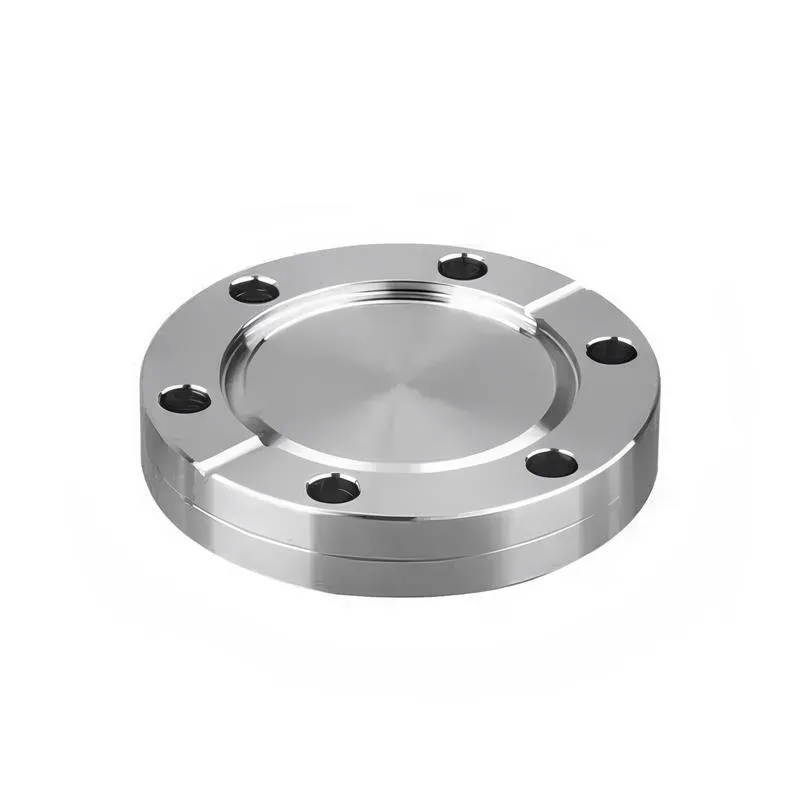
A flange—also referred to as a flange plate or rim—is a component used to connect shafts to one another, or, more commonly, to join the ends of pipes. Flanges are also utilized at the inlet and outlet ports of equipment to facilitate connections between two devices—for instance, the flange on a speed reducer. A "flange connection" or "flanged joint" refers to a detachable joint assembly comprising three interconnected elements—a flange, a gasket, and bolts—that together form a sealed structural unit. In the context of piping systems, a "pipe flange" specifically denotes a flange used for plumbing within the installation; when applied to equipment, it refers to the inlet or outlet flange of that specific device. Flanges feature a series of holes through which bolts are inserted to securely fasten the two flanges together, while a gasket placed between the flanges ensures a leak-proof seal. Flanges are broadly categorized into three types: threaded (screw-in) flanges, welded flanges, and clamp-type flanges. Flanges are invariably used in pairs; threaded flanges are suitable for low-pressure piping applications, whereas welded flanges are required for systems operating at pressures exceeding 4 kilograms per square centimeter. A sealing gasket is inserted between the two flange plates, which are then firmly secured using bolts. The thickness of a flange—as well as the specifications of the bolts used to fasten it—vary depending on the specific pressure rating required for the application. When connecting equipment such as water pumps or valves to piping systems, the corresponding connection points on these devices are often manufactured in the shape of a matching flange; this method of attachment is also referred to as a "flange connection." Generally, any connecting component that utilizes bolts to join and seal the perimeters of two flat surfaces—such as the joints in ventilation ducts—is termed a "flange"; such components may collectively be classified as "flange-type parts." However, since such a connection often constitutes merely a *portion* of a larger device—for instance, the interface between a flange and a water pump—it would be inappropriate to classify the entire water pump itself as a "flange-type part." Conversely, smaller components—such as valves—that feature such flanged interfaces may indeed be appropriately categorized as "flange-type parts."
-:-
For detailed product information, please contact sales.
-:
AISI 86B50 Steel Flange, oil quenched 800°C (1470°F), 540°C (1000°F) temper Product Information
-:-
For detailed product information, please contact sales.
-:
AISI 86B50 Steel Flange, oil quenched 800°C (1470°F), 540°C (1000°F) temper Synonyms
-:-
For detailed product information, please contact sales.
-:
AISI 86B50 Steel, oil quenched 800°C (1470°F), 540°C (1000°F) temper Product Information
-:-
For detailed product information, please contact sales.
-:
**Product Overview: AISI 86B50 Steel, Oil Quenched & Tempered (800°C / 540°C)**
This document provides a technical introduction to components manufactured from **AISI 86B50** alloy steel, heat-treated to a high-strength condition through **oil quenching from 800°C (1470°F) followed by tempering at 540°C (1000°F)**. This specific thermal treatment leverages the steel's boron-enhanced hardenability to produce a microstructure offering an outstanding combination of very high strength, good toughness, and excellent fatigue resistance.
**1. International Standard Designations**
* **AISI/SAE (USA):** 86B50 (The "B" denotes Boron treatment for enhanced hardenability)
* **ASTM (USA):** A304 (Standard Specification for Carbon and Alloy Steel Bars Subject to End-Quench Hardenability Requirements)
* **UNS:** G86600
* **Common Specification for Heat-Treated Bars:** ASTM A29/A29M can be invoked for heat-treated material, though final properties are often governed by customer-specific part drawings.
* **Note:** This is a distinct, boron-treated grade. Its hardenability is superior to its common non-boron counterpart (AISI 8650). Direct international equivalents are rare due to the boron addition.
**2. Chemical Composition (Weight %)**
The composition is engineered for high hardenability with lean alloying, centered on the potent effect of boron.
| Element | Content (%) | Primary Function |
| :--- | :--- | :--- |
| **Carbon (C)** | 0.48 - 0.53 | Provides core hardness and strength. |
| **Manganese (Mn)** | 0.75 - 1.00 | Enhances strength and hardenability. |
| **Silicon (Si)** | 0.15 - 0.35 | Deoxidizer, increases strength and temper resistance. |
| **Chromium (Cr)** | 0.40 - 0.60 | Improves hardenability, wear, and corrosion resistance. |
| **Nickel (Ni)** | 0.40 - 0.70 | Significantly increases toughness and hardenability. |
| **Molybdenum (Mo)** | 0.15 - 0.25 | Promotes deep hardening, strength, and high-temperature tempering resistance. |
| **Boron (B)** | 0.0005 - 0.003 | **A powerful hardenability enhancer**; ensures full martensitic transformation in larger sections. |
| **Phosphorus (P)** | ≤ 0.025 | Impurity, kept low for toughness. |
| **Sulfur (S)** | ≤ 0.025 | Impurity, affects machinability. |
| **Iron (Fe)** | Balance | - |
**3. Heat Treatment & Resulting Microstructure**
* **Austenitizing/Oil Quench:** Heated to **800°C (1470°F)** to achieve a uniform austenitic structure, followed by rapid cooling in oil. The boron addition is critical here, ensuring a deep and complete transformation to martensite even in moderate to large cross-sections.
* **Tempering:** Reheated to **540°C (1000°F)** for a specified duration, then air-cooled. This mid-to-high tempering temperature effectively relieves quenching stresses, provides a substantial increase in ductility and toughness, and precipitates fine carbides to establish a stable, high-strength condition.
* **Final Microstructure:** **Tempered Martensite**. This refined structure is responsible for the superior mechanical properties.
**4. Resulting Physical & Mechanical Properties**
*Note: Properties are highly dependent on the exact cross-section; values are typical for moderately sized sections (e.g., < 75 mm diameter).*
* **Tensile Strength:** 1050 - 1200 MPa (152,000 - 174,000 psi)
* **Yield Strength (0.2% Offset):** 950 - 1100 MPa (138,000 - 160,000 psi)
* **Elongation (in 50mm):** ≥ 12%
* **Reduction of Area:** ≥ 45%
* **Hardness:** 32 - 38 HRC (Approx. 300 - 350 HBW)
* **Impact Toughness (Charpy V-notch):** Good for this strength level, a direct benefit of the nickel content and the 540°C temper.
* **Fatigue Strength:** Excellent, a key characteristic of the clean, tempered martensitic microstructure.
**Physical Properties (Approximate at 20°C):**
* **Density:** 7.85 g/cm³
* **Modulus of Elasticity:** 205 GPa (29,700 ksi)
* **Poisson's Ratio:** 0.29
* **Thermal Conductivity:** ~42.0 W/m·K
**5. Key Characteristics & Advantages**
* **High Strength with Good Toughness:** The specific tempering temperature provides an optimal balance, avoiding the embrittlement risks associated with lower tempering ranges.
* **Superior Hardenability:** Boron allows for excellent through-hardening in larger sections, ensuring uniform core properties and performance.
* **Excellent Fatigue and Wear Resistance:** Ideal for dynamically loaded components and applications involving sliding contact.
* **Cost-Effective Performance:** The lean alloy design (enhanced by boron) provides performance comparable to more highly alloyed steels at a lower cost.
* **Good Machinability (in annealed/normalized state):** Parts are typically fully machined prior to this final heat treatment.
**6. Typical Applications**
This heat-treated condition is specified for highly stressed, safety-critical components requiring reliability under cyclic loading. Common applications include:
* **Automotive & Truck:** High-strength axle shafts, torsion bars, steering components, and critical suspension parts.
* **Power Transmission:** Heavy-duty gears, pinions, and drive shafts for industrial machinery and off-highway vehicles.
* **Oil & Gas:** Drill string components (e.g., subs), tool joints, and high-grade fasteners.
* **Heavy Equipment:** Track pins, bushings, linkage arms, and pivot shafts for construction and mining machinery.
* **Agriculture:** High-stress driveline and implement components.
**7. Available Form & Notes**
* **Form:** Supplied as finished or semi-finished **components** (e.g., machined forgings, turned bars) in this heat-treated condition.
* **Condition:** **Oil Quenched from 800°C and Tempered at 540°C**.
* **Post-Treatment Machining:** Limited grinding or hard machining is possible; welding is not recommended without extensive pre- and post-weld heat treatment.
* **Quality Verification:** Properties are typically verified through hardness testing and often tensile/impact testing on sample coupons from the same heat treat lot.
**Disclaimer:** The properties listed are representative. For engineering design, exact property guarantees must be agreed upon with the supplier, considering the specific part geometry and relevant testing standards (e.g., ASTM A370). The boron-treated grade requires precise heat treatment control to realize its full potential.
-:-
For detailed product information, please contact sales.
-:
AISI 86B50 Steel, oil quenched 800°C (1470°F), 540°C (1000°F) temper Specification
Dimensions
Size:
Diameter 20-1000 mm Length <6377 mm
Size:We can customized as required
Standard:
Per your request or drawing
We can customized as required
Properties(Theoretical)
Chemical Composition
-:-
For detailed product information, please contact sales.
-:
AISI 86B50 Steel, oil quenched 800°C (1470°F), 540°C (1000°F) temper Properties
-:-
For detailed product information, please contact sales.
-:
Applications of AISI 86B50 Steel Flange, oil quenched 800°C (1470°F), 540°C (1000°F) temper
-:-
For detailed product information, please contact sales.
-:
Chemical Identifiers AISI 86B50 Steel Flange, oil quenched 800°C (1470°F), 540°C (1000°F) temper
-:-
For detailed product information, please contact sales.
-:
Packing of AISI 86B50 Steel Flange, oil quenched 800°C (1470°F), 540°C (1000°F) temper
-:-
For detailed product information, please contact sales.
-:
Standard Packing:
-:-
For detailed product information, please contact sales.
-:
Typical bulk packaging includes palletized plastic 5 gallon/25 kg. pails, fiber and Steel Flange drums to 1 ton super sacks in full container (FCL) or truck load (T/L) quantities. Research and sample quantities and hygroscopic, oxidizing or other air sensitive materials may be packaged under argon or vacuum. Solutions are packaged in polypropylene, plastic or glass jars up to palletized 2848 gallon liquid totes Special package is available on request. E FORUs’ is carefully handled to minimize damage during storage and transportation and to preserve the quality of our products in their original condition


")
 Hot Work Tool Steel Flange")
