1,We Manufacturing processes are primarily classified into four types:
1:Forging,
2:Casting,
3:Cutting,
4:Rolling.
2,We can manufacture in accordance with these standards.
Standards:
GB Series (Chinese Standards), JB Series (Machinery Standards), HG Series (Chemical Industry Standards), ASME B16.5 (American Standards), BS4504 (British Standards), DIN (German Standards), and JIS (Japanese Standards).
Internationally, there are two primary systems of pipe flange standards: the European system, represented by the German DIN standards (including those of the former Soviet Union), and the American system, represented by the US ANSI pipe flange standards. Other common standards include: the Chinese Ministry of Machinery Industry standards (JB series), the Ministry of Chemical Industry standards (HG series), the Chinese National Standard *GB/T 9112–9124-2010 Steel Pipe Flanges*, as well as US standards (ASME B16.5), British standards (BS4504), German standards (DIN), Japanese standards (JIS), and marine standards (CBM), among others.
The nominal pressure ratings for the PN series are designated by "PN" and comprise the following nine levels: PN2.5, PN6, PN10, PN16, PN25, PN40, PN63, PN100, and PN160.
The nominal pressure ratings for the Class series are designated by "Class" and comprise the following six levels: Class150, Class300, Class600, Class900, Class1500, and Class2500.
Flange Classification
1. **According to Chemical Industry Standards:** Flanges are classified as follows:
Plate Flat Welding Flange (PL), Necked Flat Welding Flange (SO), Necked Butt Welding Flange (WN), Integral Flange (IF), Socket Welding Flange (SW), Threaded Flange (Th), Butt Welding Ring Loose Flange (PJ/SE), Blind Flange (BL), Flat Welding Ring Loose Flange (PJ/PJ), and Lined Blind Flange (BL(s)).
2. **According to Petrochemical (SH) Industry Standards:** Flanges are classified as follows:
Threaded Flange (PL), Butt Welding Flange (WN), Flat Welding Flange (SO), Socket Welding Flange (SW), Loose Flange (LJ), and Blind Flange (no specific designation).
3. **According to Machinery (JB) Industry Standards:** Flanges are classified as follows:
Integral Flange, Butt Welding Flange, Plate Flat Welding Flange, Butt Welding Ring Plate Loose Flange, Flat Welding Ring Plate Loose Flange, Lap Joint Ring Plate Loose Flange, and Blind Flange.
4. **According to Connection Method/Type:** Flanges are classified as follows:
Plate Flat Welding Flange, Necked Flat Welding Flange, Necked Butt Welding Flange, Socket Welding Flange, Threaded Flange, Blind Flange, Necked Butt Welding Ring Loose Flange, Flat Welding Ring Loose Flange, Ring-Type Joint (RTJ) Flange and Blind Flange, Large-Diameter Plate Flange, Large-Diameter High-Neck Flange, Figure-8 Blind Plate, Butt Welding Ring Loose Flange, etc.
5. **According to the Component Being Connected:** Flanges can be classified into Vessel Flanges and Pipe Flanges.
6. **According to Structural Type:** Flanges include Integral Flanges, Threaded Flanges, Flat Welding Flanges, Butt Welding Flanges, Lap Joint (Loose/Swivel) Flanges, and Blind Flanges.
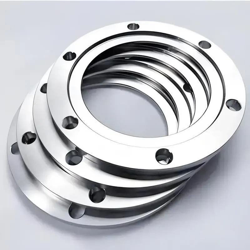
A flange—also referred to as a flange plate or rim—is a component used to connect shafts to one another, or, more commonly, to join the ends of pipes. Flanges are also utilized at the inlet and outlet ports of equipment to facilitate connections between two devices—for instance, the flange on a speed reducer. A "flange connection" or "flanged joint" refers to a detachable joint assembly comprising three interconnected elements—a flange, a gasket, and bolts—that together form a sealed structural unit. In the context of piping systems, a "pipe flange" specifically denotes a flange used for plumbing within the installation; when applied to equipment, it refers to the inlet or outlet flange of that specific device. Flanges feature a series of holes through which bolts are inserted to securely fasten the two flanges together, while a gasket placed between the flanges ensures a leak-proof seal. Flanges are broadly categorized into three types: threaded (screw-in) flanges, welded flanges, and clamp-type flanges. Flanges are invariably used in pairs; threaded flanges are suitable for low-pressure piping applications, whereas welded flanges are required for systems operating at pressures exceeding 4 kilograms per square centimeter. A sealing gasket is inserted between the two flange plates, which are then firmly secured using bolts. The thickness of a flange—as well as the specifications of the bolts used to fasten it—vary depending on the specific pressure rating required for the application. When connecting equipment such as water pumps or valves to piping systems, the corresponding connection points on these devices are often manufactured in the shape of a matching flange; this method of attachment is also referred to as a "flange connection." Generally, any connecting component that utilizes bolts to join and seal the perimeters of two flat surfaces—such as the joints in ventilation ducts—is termed a "flange"; such components may collectively be classified as "flange-type parts." However, since such a connection often constitutes merely a *portion* of a larger device—for instance, the interface between a flange and a water pump—it would be inappropriate to classify the entire water pump itself as a "flange-type part." Conversely, smaller components—such as valves—that feature such flanged interfaces may indeed be appropriately categorized as "flange-type parts."
-:-
For detailed product information, please contact sales.
-:
AISI Type L5 Tool Steel Flange Product Information
-:-
For detailed product information, please contact sales.
-:
AISI Type L5 Tool Steel Flange Synonyms
-:-
For detailed product information, please contact sales.
-:
AISI Type L5 Tool Steel Product Information
-:-
For detailed product information, please contact sales.
-:
# **Product Introduction: AISI Type L5 (UNS T61205) High-Chromium Impact Tool Steel**
## **Overview**
AISI Type L5 is a **medium-carbon, high-chromium** oil-hardening tool steel within the AISI "L-series" (Low-Alloy, Special Purpose). Characterized by its **optimized chromium content (approximately 1.00%)** combined with carefully balanced carbon levels, L5 offers exceptional **toughness and shock resistance** while maintaining adequate wear characteristics. This grade is specifically engineered for applications requiring reliable performance under impact loading conditions, serving as a cost-effective alternative to more specialized shock-resistant steels for many demanding tooling applications.
**Key Advantages:**
- **Excellent Impact Resistance:** Superior toughness and resistance to chipping under shock loading
- **Good Hardenability:** Reliable through-hardening in moderate sections via oil quenching
- **Balanced Wear Resistance:** Adequate carbide formation for moderate service conditions
- **Minimal Processing Distortion:** Predictable dimensional changes during heat treatment
- **Economic Viability:** Cost-effective solution for impact tooling applications
**Primary Considerations:**
- Maximum hardness limited compared to higher-carbon tool steels
- Requires precise tempering to optimize toughness-hardness balance
- Best performance in applications where impact resistance is prioritized over extreme wear
## **International Designations & Standards**
| Standard System | Designation | Note |
|----------------|-------------|------|
| **AISI/SAE (USA)** | L5 | Primary specification |
| **UNS (USA)** | T61205 | Unified numbering system |
| **ASTM (USA)** | A681 | Governing material standard |
| **DIN (Germany)** | ~1.2414 | Similar chromium tool steel |
| **BS (UK)** | ~**BH2** | Related oil-hardening grade |
| **JIS (Japan)** | ~SKS3 | Similar special purpose tool steel |
| **ISO (International)** | ~**100Cr2** | Closest functional equivalent |
*Note: International equivalents vary due to national composition preferences. AISI L5 is distinguished by its balanced approach to providing both hardenability and toughness.*
---
## **1. Chemical Composition (Typical, Weight %)**
The composition provides a balance between hardenability, toughness, and wear resistance through controlled chromium and carbon levels.
| Element | Content (%) | Role & Metallurgical Effect |
|---------|-------------|-----------------------------|
| **Carbon (C)** | 0.50 - 0.70 | Provides base hardness and strength. Maintained at moderate levels to optimize toughness while ensuring adequate hardness for tooling applications. |
| **Chromium (Cr)** | 0.90 - 1.20 | Primary alloying element. Enhances hardenability depth, contributes to wear resistance through carbide formation, and improves tempering response. |
| **Manganese (Mn)** | 0.25 - 0.50 | Supports hardenability and promotes austenite stability during heat treatment. |
| **Silicon (Si)** | 0.10 - 0.30 | Deoxidizer, provides solid solution strengthening, improves resistance to temper softening. |
| **Vanadium (V)** | 0.10 - 0.20 (Optional) | When added, refines grain structure and improves toughness through fine carbide precipitation. |
| **Molybdenum (Mo)**| 0.15 - 0.30 (Optional) | Enhances hardenability and toughness, particularly beneficial for larger cross-sections. |
| **Phosphorus (P)** | ≤0.025 | Controlled impurity to prevent temper embrittlement. |
| **Sulfur (S)** | ≤0.025 | Controlled impurity; may be adjusted for machinability in certain applications. |
| **Iron (Fe)** | Balance | Matrix element. |
**Composition Variations:**
- **Standard L5:** Optimized for general impact applications with balanced properties
- **Modified L5:** May include vanadium or molybdenum additions for specific performance requirements
---
## **2. Physical & Mechanical Properties**
### **Physical Properties**
| Property | Typical Value | Conditions/Notes |
|----------|---------------|------------------|
| **Density** | 7.81 - 7.83 g/cm³ | At 20°C (68°F) |
| **Melting Range** | 1425 - 1445°C (2597 - 2633°F) | Liquidus to solidus range |
| **Thermal Conductivity** | 44 - 48 W/m·K | At 20°C (68°F) |
| **Specific Heat Capacity** | 465 - 485 J/kg·K | At 20°C (68°F) |
| **Coefficient of Thermal Expansion** | 11.7 - 12.2 × 10⁻⁶/K | 20-200°C (68-392°F) range |
| **Electrical Resistivity** | 0.27 - 0.31 μΩ·m | At 20°C (68°F) |
| **Elastic Modulus** | 206 - 210 GPa (29.9 - 30.5 × 10⁶ psi) | At room temperature |
### **Mechanical Properties (Heat-Treated Condition)**
| Property | Value Range | Heat Treatment Condition |
|----------|-------------|--------------------------|
| **Hardness (Annealed)** | 183 - 212 HB | Spheroidize annealed condition |
| **Hardness (Hardened)** | 54 - 58 HRC | Oil quenched from 830-860°C, tempered at 200-350°C |
| **Tensile Strength** | 1750 - 1950 MPa (254 - 283 ksi) | At 56-58 HRC |
| **Yield Strength (0.2% offset)** | 1450 - 1650 MPa (210 - 239 ksi) | At 56-58 HRC |
| **Compressive Strength** | 2100 - 2350 MPa (305 - 341 ksi) | At 56-58 HRC |
| **Impact Toughness (Charpy)** | 25 - 35 J (18 - 26 ft·lb) | At 56-58 HRC, unnotched |
| **Fatigue Endurance Limit** | 650 - 750 MPa (94 - 109 ksi) | Rotating bending, 10⁷ cycles |
| **Fracture Toughness (K₁c)** | 40 - 50 MPa√m | At 56-58 HRC |
### **Hardenability Data (Jominy Test Typical)**
| Distance from Quenched End (1/16 in) | 1 | 4 | 8 | 12 | 16 | 20 |
|--------------------------------------|---|---|---|---|---|---|
| **Hardness (HRC)** | 58-60 | 57-59 | 56-58 | 55-57 | 54-56 | 53-55 |
*Through-hardening capability: Approximately 75-100mm (3-4 inches) diameter in oil quench.*
---
## **3. Product Applications**
### **Primary Application Areas**
**1. Impact and Shock Tools:**
- Cold chisels and pneumatic tool components
- Demolition tools and heavy-duty hand tools
- Blacksmith tools and hot work applications (secondary)
- Rivet busters and scaling hammers
**2. Forming and Forging Applications:**
- Cold heading dies for medium-duty applications
- Swaging tools and forming dies
- Bending dies requiring shock resistance
- Extrusion tooling for softer materials
**3. Cutting Tools (Impact-Resistant):**
- Heavy-duty lathe tools for interrupted cutting
- Milling cutters and gear cutters
- Broaches for tough materials
- Woodworking tools for hardwoods
**4. Wear Components Subject to Impact:**
- Machine tool components (slides, gibs, ways)
- Agricultural implement parts
- Mining tool components
- Gear blanks and sprockets
### **Industry-Specific Applications**
| Industry | Typical L5 Components |
|----------|-----------------------|
| **Metalworking** | Heavy-duty punches, forming dies, shear blades |
| **Fastener Manufacturing** | Cold heading dies, thread rolling dies |
| **Construction** | Demolition tools, concrete breakers, cutting edges |
| **Agriculture** | Plow shares, cultivator points, harrow teeth |
| **Mining** | Drill bits, cutter picks, extraction tool components |
### **Service Performance Characteristics**
| Service Condition | L5 Performance | Recommended Hardness Range |
|-------------------|----------------|----------------------------|
| **Heavy Impact** | Excellent | 54-56 HRC |
| **Moderate Impact with Wear** | Good | 56-58 HRC |
| **Cyclic Loading** | Good to Very Good | 55-57 HRC |
| **Combined Stresses** | Good | 55-57 HRC |
| **Abrasive Conditions** | Fair to Good | 57-58 HRC |
---
## **4. Heat Treatment Guidelines**
### **Annealing (Preparation for Machining)**
- **Process:** Full annealing or spheroidize annealing
- **Temperature:** 790-810°C (1455-1490°F)
- **Cooling:** Slow furnace cool at ≤20°C/hr to 540°C, then air cool
- **Resulting Hardness:** 183-212 HB
- **Microstructure:** Uniform spheroidized carbides
### **Hardening (Austenitizing & Quenching)**
1. **Preheating:** Recommended to minimize distortion
- Stage 1: 400-500°C (750-930°F)
- Stage 2: 650-700°C (1200-1290°F)
2. **Austenitizing:**
- **Temperature:** 830-860°C (1525-1580°F)
- **Soaking Time:** 20-30 minutes per inch of thickness
- **Atmosphere:** Neutral to slightly carburizing
- **Target Grain Size:** ASTM 8-9
3. **Quenching:**
- **Medium:** Warm oil (50-80°C / 120-175°F)
- **Agitation:** Moderate to ensure uniform cooling
- **Quench to:** 60-80°C (140-175°F) before tempering
### **Tempering (Critical for Toughness Development)**
- **Time to Temper:** Within 1-2 hours of quenching
- **Standard Practice:** Double tempering recommended
- First temper: 200-350°C (400-660°F) for 2+ hours
- Second temper: Same or slightly higher temperature, 2+ hours
- **Hardness-Temperature Relationship:**
- 150°C (300°F): 57-59 HRC
- 200°C (400°F): 56-58 HRC
- 250°C (480°F): 55-57 HRC
- 300°C (570°F): 54-56 HRC
- 350°C (660°F): 53-55 HRC
- 400°C (750°F): 51-53 HRC
### **Stress Relieving**
- **When:** After rough machining, before final hardening
- **Temperature:** 600-650°C (1110-1200°F)
- **Hold Time:** 1-2 hours per inch
- **Cooling:** Slow furnace cool
---
## **5. Comparative Analysis**
### **vs. Other L-Series Grades**
| Property | L5 | L4 | L6 | S5 (Shock Steel) |
|----------|----|----|----|------------------|
| **Carbon Content** | Medium-Low (0.50-0.70%) | Medium (0.65-0.85%) | Medium (0.65-0.75%) | Low (0.50-0.60%) |
| **Chromium Content** | Medium (0.90-1.20%) | High (1.20-1.80%) | Medium (0.60-1.00%) | Low (0.50-0.80%) |
| **Primary Strength** | Impact toughness | Balanced toughness | High toughness | Extreme impact |
| **Typical Hardness** | 54-58 HRC | 56-60 HRC | 56-60 HRC | 52-56 HRC |
| **Charpy Impact** | 25-35 J | 18-25 J | 20-30 J | 35-50 J |
| **Relative Cost** | 0.9x | 1.0x | 1.0x | 1.3x |
### **Performance Comparison**
| Application Type | L5 Suitability | Alternative Grades |
|-----------------|----------------|-------------------|
| **Heavy Impact Tools** | Very Good | S5, S7 |
| **Wear with Impact** | Good | L4, L6 |
| **Precision Tooling** | Fair | O1, A2 |
| **High Production** | Fair to Good | D2, M2 |
---
## **6. Technical Recommendations**
### **Design Considerations**
1. **Stress Concentrations:** Minimum radius of 1.5mm on internal corners
2. **Section Thickness:** Maintain uniformity where possible
3. **Hardness Requirements:** Specify based on primary service conditions
4. **Surface Finish:** Critical wear surfaces should be 1.6μm Ra or better
### **Quality Control Points**
- Verify chemical composition against specifications
- Monitor decarburization during processing (max 0.10mm)
- Conduct hardness testing at multiple locations
- Verify microstructure after heat treatment
### **Safety and Handling**
- **Heat Treatment:** Follow standard furnace safety procedures
- **Machining:** Use appropriate dust collection
- **Storage:** Protect from corrosion with preventive coatings
- **Disposal:** Recycle as alloy steel scrap
---
## **Disclaimer**
This technical datasheet provides general information about AISI Type L5 tool steel. Actual performance may vary based on:
1. **Manufacturing variations** between different steel producers
2. **Specific heat treatment parameters** and equipment
3. **Application conditions** and service environment
4. **Design factors** and manufacturing quality
**For critical applications:**
- Consult with materials engineering specialists
- Conduct application-specific testing
- Develop detailed processing specifications
- Consider alternative materials for extreme conditions
Always refer to current standards and supplier specifications for specific requirements. This information is subject to revision as technology and standards evolve.
-:-
For detailed product information, please contact sales.
-:
AISI Type L5 Tool Steel Specification
Dimensions
Size:
Diameter 20-1000 mm Length <6709 mm
Size:We can customized as required
Standard:
Per your request or drawing
We can customized as required
Properties(Theoretical)
Chemical Composition
-:-
For detailed product information, please contact sales.
-:
AISI Type L5 Tool Steel Properties
-:-
For detailed product information, please contact sales.
-:
Applications of AISI Type L5 Tool Steel Flange
-:-
For detailed product information, please contact sales.
-:
Chemical Identifiers AISI Type L5 Tool Steel Flange
-:-
For detailed product information, please contact sales.
-:
Packing of AISI Type L5 Tool Steel Flange
-:-
For detailed product information, please contact sales.
-:
Standard Packing:
-:-
For detailed product information, please contact sales.
-:
Typical bulk packaging includes palletized plastic 5 gallon/25 kg. pails, fiber and Steel Flange drums to 1 ton super sacks in full container (FCL) or truck load (T/L) quantities. Research and sample quantities and hygroscopic, oxidizing or other air sensitive materials may be packaged under argon or vacuum. Solutions are packaged in polypropylene, plastic or glass jars up to palletized 3180 gallon liquid totes Special package is available on request. E FORUs’ is carefully handled to minimize damage during storage and transportation and to preserve the quality of our products in their original condition