1,We Manufacturing processes are primarily classified into four types:
1:Forging,
2:Casting,
3:Cutting,
4:Rolling.
2,We can manufacture in accordance with these standards.
Standards:
GB Series (Chinese Standards), JB Series (Machinery Standards), HG Series (Chemical Industry Standards), ASME B16.5 (American Standards), BS4504 (British Standards), DIN (German Standards), and JIS (Japanese Standards).
Internationally, there are two primary systems of pipe flange standards: the European system, represented by the German DIN standards (including those of the former Soviet Union), and the American system, represented by the US ANSI pipe flange standards. Other common standards include: the Chinese Ministry of Machinery Industry standards (JB series), the Ministry of Chemical Industry standards (HG series), the Chinese National Standard *GB/T 9112–9124-2010 Steel Pipe Flanges*, as well as US standards (ASME B16.5), British standards (BS4504), German standards (DIN), Japanese standards (JIS), and marine standards (CBM), among others.
The nominal pressure ratings for the PN series are designated by "PN" and comprise the following nine levels: PN2.5, PN6, PN10, PN16, PN25, PN40, PN63, PN100, and PN160.
The nominal pressure ratings for the Class series are designated by "Class" and comprise the following six levels: Class150, Class300, Class600, Class900, Class1500, and Class2500.
Flange Classification
1. **According to Chemical Industry Standards:** Flanges are classified as follows:
Plate Flat Welding Flange (PL), Necked Flat Welding Flange (SO), Necked Butt Welding Flange (WN), Integral Flange (IF), Socket Welding Flange (SW), Threaded Flange (Th), Butt Welding Ring Loose Flange (PJ/SE), Blind Flange (BL), Flat Welding Ring Loose Flange (PJ/PJ), and Lined Blind Flange (BL(s)).
2. **According to Petrochemical (SH) Industry Standards:** Flanges are classified as follows:
Threaded Flange (PL), Butt Welding Flange (WN), Flat Welding Flange (SO), Socket Welding Flange (SW), Loose Flange (LJ), and Blind Flange (no specific designation).
3. **According to Machinery (JB) Industry Standards:** Flanges are classified as follows:
Integral Flange, Butt Welding Flange, Plate Flat Welding Flange, Butt Welding Ring Plate Loose Flange, Flat Welding Ring Plate Loose Flange, Lap Joint Ring Plate Loose Flange, and Blind Flange.
4. **According to Connection Method/Type:** Flanges are classified as follows:
Plate Flat Welding Flange, Necked Flat Welding Flange, Necked Butt Welding Flange, Socket Welding Flange, Threaded Flange, Blind Flange, Necked Butt Welding Ring Loose Flange, Flat Welding Ring Loose Flange, Ring-Type Joint (RTJ) Flange and Blind Flange, Large-Diameter Plate Flange, Large-Diameter High-Neck Flange, Figure-8 Blind Plate, Butt Welding Ring Loose Flange, etc.
5. **According to the Component Being Connected:** Flanges can be classified into Vessel Flanges and Pipe Flanges.
6. **According to Structural Type:** Flanges include Integral Flanges, Threaded Flanges, Flat Welding Flanges, Butt Welding Flanges, Lap Joint (Loose/Swivel) Flanges, and Blind Flanges.
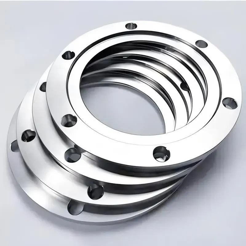
A flange—also referred to as a flange plate or rim—is a component used to connect shafts to one another, or, more commonly, to join the ends of pipes. Flanges are also utilized at the inlet and outlet ports of equipment to facilitate connections between two devices—for instance, the flange on a speed reducer. A "flange connection" or "flanged joint" refers to a detachable joint assembly comprising three interconnected elements—a flange, a gasket, and bolts—that together form a sealed structural unit. In the context of piping systems, a "pipe flange" specifically denotes a flange used for plumbing within the installation; when applied to equipment, it refers to the inlet or outlet flange of that specific device. Flanges feature a series of holes through which bolts are inserted to securely fasten the two flanges together, while a gasket placed between the flanges ensures a leak-proof seal. Flanges are broadly categorized into three types: threaded (screw-in) flanges, welded flanges, and clamp-type flanges. Flanges are invariably used in pairs; threaded flanges are suitable for low-pressure piping applications, whereas welded flanges are required for systems operating at pressures exceeding 4 kilograms per square centimeter. A sealing gasket is inserted between the two flange plates, which are then firmly secured using bolts. The thickness of a flange—as well as the specifications of the bolts used to fasten it—vary depending on the specific pressure rating required for the application. When connecting equipment such as water pumps or valves to piping systems, the corresponding connection points on these devices are often manufactured in the shape of a matching flange; this method of attachment is also referred to as a "flange connection." Generally, any connecting component that utilizes bolts to join and seal the perimeters of two flat surfaces—such as the joints in ventilation ducts—is termed a "flange"; such components may collectively be classified as "flange-type parts." However, since such a connection often constitutes merely a *portion* of a larger device—for instance, the interface between a flange and a water pump—it would be inappropriate to classify the entire water pump itself as a "flange-type part." Conversely, smaller components—such as valves—that feature such flanged interfaces may indeed be appropriately categorized as "flange-type parts."
-:-
For detailed product information, please contact sales.
-:
AISI Type M3 Class 2 Molybdenum High Speed Tool Steel Flange (UNS T11323) Product Information
-:-
For detailed product information, please contact sales.
-:
AISI Type M3 Class 2 Molybdenum High Speed Tool Steel Flange (UNS T11323) Synonyms
-:-
For detailed product information, please contact sales.
-:
AISI Type M3 Class 2 Molybdenum High Speed Tool Steel (UNS T11323) Product Information
-:-
For detailed product information, please contact sales.
-:
# **Product Introduction: AISI Type M3 Class 2 Ultra-High-Vanadium Molybdenum High-Speed Tool Steel (UNS T11323)**
## **Overview**
AISI Type M3 Class 2 is an **ultra-high-vanadium, high-carbon molybdenum-tungsten high-speed steel** representing the **highest vanadium variant** within the M3 classification. Characterized by its **exceptionally high vanadium (2.75-3.25%) and carbon (1.15-1.25%) content**, this grade is engineered for **maximum wear resistance and abrasion performance** in the most demanding cutting applications. M3 Class 2 provides **superior edge retention and tool life** when machining highly abrasive materials, positioning it as a specialized solution for extreme wear conditions where standard and even high-vanadium HSS grades prove inadequate.
**Key Advantages:**
- **Exceptional Wear Resistance:** Ultra-high vanadium carbide content provides outstanding abrasion resistance
- **Superior Edge Retention:** Maintains sharp cutting edges longer in abrasive conditions
- **Good Hot Hardness:** Maintains performance at elevated temperatures despite high wear focus
- **Optimized for Abrasion:** Specifically engineered for maximum wear resistance
- **Proven Performance:** Established track record in severe abrasive applications
**Primary Considerations:**
- **Poor Grindability:** Very challenging to grind due to high vanadium carbide content
- **Reduced Toughness:** Lower impact resistance compared to lower-vanadium grades
- **Higher Cost:** Premium pricing due to alloy content and processing challenges
- **Specialized Application:** Not suitable for general-purpose or high-impact applications
## **International Designations & Standards**
| Standard System | Designation | Note |
|----------------|-------------|------|
| **AISI/SAE (USA)** | M3 Class 2 | Primary specification |
| **UNS (USA)** | T11323 | Unified numbering system |
| **ASTM (USA)** | A600 | High-Speed Tool Steel Standard |
| **ISO (International)** | ~**HS6-5-3-8** | Similar high-vanadium composition |
| **DIN (Germany)** | 1.3346 | High-vanadium HSS equivalent |
| **JIS (Japan)** | SKH53 | Ultra-high-vanadium HSS |
| **BS (UK)** | ~**BM3/2** | High-vanadium HSS Class 2 |
| **GB (China)** | W6Mo5Cr4V3Al | Similar high-vanadium HSS |
| **AFNOR (France)** | ~Z130WDCV06-05-04-04 | French high-vanadium designation |
*Note: M3 Class 2 represents the extreme end of conventional high-vanadium HSS grades, with specific focus on maximum wear resistance.*
---
## **1. Chemical Composition (Typical, Weight %)**
M3 Class 2 features the highest vanadium and carbon content in the M3 series, optimized for extreme wear resistance.
| Element | Content (%) | Role & Metallurgical Effect |
|---------|-------------|-----------------------------|
| **Carbon (C)** | 1.15 - 1.25 | **Critical high level.** Provides carbon for extensive vanadium carbide formation and maintains matrix hardness. Highest in M3 series. |
| **Vanadium (V)** | 2.75 - 3.25 | **Ultra-high wear element.** Forms massive amounts of extremely hard vanadium carbides (VC, V₄C₃) that provide exceptional abrasion resistance. Highest practical level in conventional HSS. |
| **Tungsten (W)** | 5.00 - 6.75 | Provides hot hardness through tungsten carbide formation. Balanced with molybdenum. |
| **Molybdenum (Mo)** | 4.75 - 6.50 | Enhanced level to balance tungsten and provide cost-effective hot hardness. |
| **Chromium (Cr)** | 3.75 - 4.50 | Standard for hardenability and oxidation resistance. |
| **Cobalt (Co)** | 0.0 - 1.50 (Optional) | Sometimes added for specific high-temperature abrasive applications. |
| **Silicon (Si)** | 0.20 - 0.45 | Deoxidizer and matrix strengthener. |
| **Manganese (Mn)** | 0.15 - 0.40 | Enhances hardenability. |
| **Sulfur (S)** | ≤0.030 | Residual impurity. |
| **Phosphorus (P)** | ≤0.030 | Residual impurity. |
| **Iron (Fe)** | Balance | Matrix element. |
**Key Metallurgical Features:**
- **Vanadium Carbide Volume:** ~12-18% (highest in M3 series)
- **Carbon-Vanadium Ratio:** Optimized for maximum VC formation
- **Primary Carbides:** Dominated by MC-type (vanadium-rich)
- **Carbide Size:** Generally finer than in lower-alloy grades with proper processing
- **Austenitizing Temperature:** 1200-1240°C (2190-2265°F)
---
## **2. Physical & Mechanical Properties**
### **Physical Properties**
| Property | Typical Value | Conditions/Notes |
|----------|---------------|------------------|
| **Density** | 8.10 - 8.20 g/cm³ | At 20°C (68°F) |
| **Melting Range** | 1360 - 1410°C (2480 - 2570°F) | |
| **Thermal Conductivity** | 21 - 26 W/m·K | At 20°C (68°F) - Lower due to high carbide content |
| **Specific Heat Capacity** | 415 - 455 J/kg·K | At 20°C (68°F) |
| **Coefficient of Thermal Expansion** | 10.7 - 11.5 × 10⁻⁶/K | 20-600°C (68-1110°F) range |
| **Electrical Resistivity** | 0.56 - 0.64 μΩ·m | At 20°C (68°F) |
| **Elastic Modulus** | 210 - 220 GPa (30.5 - 31.9 × 10⁶ psi) | At room temperature |
| **Thermal Diffusivity** | 5.8 - 6.8 mm²/s | At 20°C (68°F) |
### **Mechanical Properties (Properly Heat-Treated)**
| Property | Value Range | Heat Treatment Condition |
|----------|-------------|--------------------------|
| **Hardness (Annealed)** | 248 - 293 HB | Annealed condition |
| **Hardness (Hardened)** | 65 - 67 HRC | Triple tempered condition |
| **Hot Hardness (600°C)** | 57 - 60 HRC | After 4 hours at temperature |
| **Transverse Rupture Strength** | 3000 - 3600 MPa (435 - 522 ksi) | At 66 HRC |
| **Compressive Strength** | 3800 - 4400 MPa (551 - 638 ksi) | At 66 HRC |
| **Impact Toughness (Charpy)** | 10 - 18 J (7.4 - 13.3 ft·lb) | At 66 HRC - Lower due to high carbide content |
| **Young's Modulus** | 210 - 220 GPa (30.5 - 31.9 × 10⁶ psi) | At room temperature |
| **Fatigue Strength** | 700 - 850 MPa (102 - 123 ksi) | Rotating bending, 10⁷ cycles |
### **Wear Performance Comparison**
| Property | M3 Class 2 | M3 Class 1 | M2 | Improvement over M2 |
|----------|------------|------------|----|-------------------|
| **Abrasive Wear Resistance** | Outstanding | Very Good | Good | 50-80% better |
| **Adhesive Wear Resistance** | Excellent | Good | Fair | 40-60% better |
| **Edge Retention (abrasive)** | Exceptional | Very Good | Good | 60-100% longer |
| **Crater Wear Resistance** | Very Good | Good | Fair | 30-50% better |
| **Overall Tool Life (abrasive)** | 2-3x M3 Class 1 | 1.5-2x M2 | Baseline | 3-5x M2 in severe abrasion |
### **Grindability Characteristics**
- **Relative Grindability:** 40-50% (compared to M2 = 100%)
- **Wheel Selection:** **Diamond or CBN essential** for efficient grinding
- **Wheel Life:** 20-40% of M2 grinding
- **Power Requirement:** 40-60% higher than M2
- **Surface Finish:** Challenging, requires specialized technique
- **Grinding Cost:** 2-3x higher than M2
---
## **3. Product Applications**
### **Primary Application Areas**
**1. Extreme Abrasive Material Machining:**
- Cutting tools for **high-silicon aluminum alloys** (Si >12%)
- Tools for **metal matrix composites** (MMCs) and ceramic composites
- Cutting tools for **fiber-reinforced plastics** (CFRP, GFRP)
- Tools for **abrasive cast irons** with high carbide content
**2. Severe Production Environments:**
- Gear hobs for **powder metal parts** and sintered materials
- Broaches for **abrasive non-ferrous alloys**
- Form tools for **high-volume abrasive material production**
- Milling cutters for **continuous severe abrasive conditions**
**3. Specialized Industrial Applications:**
- Cutting tools for **hard facing materials** and weld overlays
- Tools for **mining and mineral processing** components
- Cutting tools for **abrasive rubber** and composite materials
- Tools for **glass-filled plastics** and reinforced polymers
### **Industry-Specific Applications**
| Industry | Typical M3 Class 2 Components | Performance Rationale |
|----------|------------------------------|-----------------------|
| **Automotive** | Cylinder liner machining tools, brake component tools | Handles high-silicon aluminum, composite materials |
| **Aerospace** | Composite material machining tools, titanium with coatings | Exceptional abrasion resistance for CFRP/MMCs |
| **Electronics** | Cutting tools for silicon wafers, ceramic substrates | Edge retention in abrasive ceramics |
| **Mining/Energy** | Valve machining tools, component repair tools | Resists abrasive particles in oil/gas applications |
| **Plastics Processing** | Cutting tools for filled polymers, recycling equipment | Handles glass, mineral, and fiber fillers |
### **Recommended Cutting Parameters**
| Work Material | Cutting Speed (m/min) | Feed (mm/tooth) | Depth of Cut | Special Considerations |
|---------------|----------------------|-----------------|--------------|-----------------------|
| **High-Si Aluminum (>12% Si)** | 100-200 | 0.10-0.25 | 1-4 mm | Diamond-coated tools often better |
| **Metal Matrix Composites** | 50-120 | 0.05-0.15 | 0.5-2 mm | Low feed, high pressure coolant |
| **Fiber-Reinforced Plastics** | 80-150 | 0.08-0.20 | 1-3 mm | Sharp edges, specialized geometry |
| **Abrasive Cast Iron** | 40-70 | 0.15-0.30 | 1-5 mm | Interrupted cuts common |
| **Hard Facing Materials** | 20-40 | 0.03-0.10 | 0.3-1.5 mm | Severe abrasion, may need even harder grades |
---
## **4. Heat Treatment Guidelines**
### **Annealing**
- **Temperature:** 850-880°C (1560-1615°F)
- **Soaking Time:** 3-4 hours minimum
- **Cooling Rate:** ≤10°C/hr to 540°C, then air cool
- **Resulting Hardness:** 248-293 HB
- **Atmosphere:** Protective atmosphere **essential** to prevent decarburization
### **Stress Relieving**
- **After Rough Machining:** 600-650°C (1110-1200°F), 2-3 hours
- **After Rough Grinding:** 550-600°C (1020-1110°F), 1-2 hours
- **Cooling:** Slow furnace cool
### **Hardening Process**
1. **Preheating (Critical - Three-stage recommended):**
- **Stage 1:** 450-550°C (840-1020°F)
- **Stage 2:** 800-850°C (1470-1560°F)
- **Stage 3:** 1050-1100°C (1920-2010°F) - **Highly recommended**
2. **Austenitizing:**
- **Temperature:** 1200-1240°C (2190-2265°F)
- **Soaking Time:** 3-6 minutes per 25mm thickness
- **Atmosphere:** **Vacuum or salt bath mandatory** for best results
- **Protection:** Pack methods only if atmosphere control unavailable
3. **Quenching:**
- **Oil Quench:** Fast quenching oil, 40-60°C, vigorous agitation
- **Salt Bath Marquench:** 500-550°C, equalize, then air cool (preferred for complex tools)
- **Press Quenching:** Recommended for flat tools to control distortion
### **Tempering (Multiple Tempers Critical)**
- **First Temper:** Begin when tool reaches 60-80°C (140-175°F)
- **Temperature:** 540-580°C (1000-1075°F)
- **Cycles:** **Minimum 3 tempers, 4 strongly recommended**
- **Duration:** 2-3 hours per temper cycle
- **Cooling:** Air cool completely between tempers
- **Final Hardness:** 65-67 HRC
- **Retained Austenite:** <5% after proper treatment
### **Sub-Zero Treatment (Highly Recommended)**
- **Temperature:** -80 to -120°C (-110 to -185°F)
- **Duration:** 3-6 hours
- **Timing:** After quenching, before first temper
- **Benefits:** Crucial for dimensional stability, maximum hardness potential
- **Hardness Increase:** 0.5-1.5 HRC typical
---
## **5. Manufacturing & Processing**
### **Machinability (Annealed Condition)**
- **Relative Machinability:** 25-35% (1% carbon steel = 100%)
- **Tool Requirements:** **Premium carbide grades essential**
- **Cutting Parameters:**
- Turning: 15-25 m/min (50-82 SFM) with carbide
- Milling: 10-18 m/min (33-60 SFM) with carbide
- Drilling: 5-8 m/min (16-26 SFM) with carbide
- **Chip Control:** Aggressive chip breakers mandatory
- **Coolant:** High-performance synthetic coolant essential
### **Grinding Operations (Challenging)**
- **Abrasive Requirements:**
- **Primary:** **Diamond wheels** (resin or metal bond)
- **Secondary:** **CBN wheels** (vitrified bond)
- **Not Recommended:** Conventional aluminum oxide wheels
- **Parameters for Diamond Wheels:**
- Wheel Speed: 20-25 m/s (4000-5000 SFPM)
- Infeed: 0.002-0.008 mm/pass
- Crossfeed: 0.5-1.5 mm/pass
- Spark-out: 3-5 passes with zero infeed
- **Coolant:** High-pressure, high-volume synthetic coolant
- **Dressing:** Frequent dressing with diamond tools
### **Electrical Discharge Machining (EDM)**
- **Suitability:** Limited - requires careful parameter control
- **Electrodes:** Premium graphite or copper-tungsten recommended
- **Parameters:** Very fine finishes, low amperage settings
- **Post-EDM:** **Mandatory** stress relief and retempering
- **White Layer:** Can be significant - requires removal by grinding
### **Surface Treatments & Coatings**
- **Recommended Coatings:** TiAlN, AlCrN, diamond-like carbon (DLC)
- **Coating Benefits:** 3-8x tool life improvement in abrasive conditions
- **Pre-coating Preparation:** Critical - surface finish <0.3 μm Ra
- **Edge Preparation:** Precision honing (0.03-0.06mm radius) essential
- **Coating Thickness:** 2-5 microns optimal
---
## **6. Comparative Analysis**
### **vs. Other High-Wear HSS Grades**
| Property | M3 Class 2 | M4 | M42 | T15 |
|----------|------------|----|-----|-----|
| **Vanadium Content** | 2.75-3.25% | 3.75-4.25% | 1.15-1.85% | 4.75-5.25% |
| **Carbon Content** | 1.15-1.25% | 1.25-1.40% | 1.05-1.15% | 1.50-1.60% |
| **Primary Strength** | Extreme wear | Maximum wear | Hot hardness | Balanced high-performance |
| **Wear Resistance** | Outstanding | Exceptional | Good | Excellent |
| **Hot Hardness** | Good | Very Good | Excellent | Excellent |
| **Toughness** | Poor | Very Poor | Fair | Poor |
| **Grindability** | Very Poor | Extremely Poor | Poor | Extremely Poor |
| **Cost Factor** | 1.6-1.9x | 1.8-2.2x | 2.0-2.2x | 2.5-3.0x |
### **Performance Positioning Matrix**
| Application Scenario | M3 Class 2 Advantage | When to Consider Alternatives |
|---------------------|----------------------|------------------------------|
| **Severe abrasive conditions** | Excellent | M4 for even more extreme abrasion |
| **High-silicon aluminum** | Outstanding | Diamond tools for highest volumes |
| **Composite materials** | Very Good | PCD for pure non-ferrous composites |
| **General abrasive improvement** | Good | M3 Class 1 for better grindability |
| **High-temperature abrasion** | Fair | M4 or cobalt grades for temperature |
### **Economic Analysis**
- **Material Cost:** 60-90% premium over M2
- **Tool Life Improvement:** 3-5x M2 in appropriate abrasive applications
- **Grinding Cost:** 3-5x higher than M2
- **Total Cost Benefit:** Positive only in specific severe abrasive applications
- **ROI Period:** 6-24 months depending on application severity
---
## **7. Quality Standards & Specifications**
### **Material Quality Requirements**
- **Chemical Composition:** Strict adherence to AISI ranges
- **Decarburization Limit:** Maximum 0.08mm per side
- **Hardness Uniformity:** ±1.0 HRC for premium applications
- **Microstructure:** Uniform fine carbide distribution critical
- **Surface Quality:** Highest standards required
### **Testing & Certification**
- **Full Chemical Analysis:** Spectrographic with full traceability
- **Hardness Mapping:** Extensive multiple point verification
- **Microstructural Examination:** Detailed carbide analysis
- **Performance Testing:** Recommended for critical applications
- **Certification:** Comprehensive documentation required
### **Industry Standards Compliance**
- **ASTM A600:** Primary governing standard
- **ISO 4957:** International tool steel standard
- **Specialized Standards:** Often customer-specific requirements
- **Quality Systems:** Typically requires ISO 9001 or equivalent
---
## **8. Technical Recommendations**
### **Selection Guidelines**
**Choose M3 Class 2 When:**
- Abrasive wear is the primary failure mode
- M3 Class 1 provides insufficient wear resistance
- Materials contain high percentages of abrasive constituents
- Tool life extension justifies premium material and processing costs
- Specialized grinding capabilities are available
**Consider Alternatives When:**
- Maximum possible wear resistance needed (M4 or specialized grades)
- Cost sensitivity outweighs performance benefits (M3 Class 1 or M2)
- Impact resistance is equally important (lower vanadium grades)
- High-temperature performance is primary concern (cobalt grades)
- Powder metallurgy benefits required (PM HSS grades)
### **Application Best Practices**
1. **Parameter Development Strategy:**
- Start very conservatively, optimize gradually
- Implement comprehensive tool monitoring
- Use condition-based maintenance strategies
2. **Tool Design Optimization:**
- Conservative geometries for maximum edge strength
- Optimized chip evacuation design
- Precision edge preparation and honing
3. **Process Integration:**
- Maximum machine rigidity essential
- Advanced workholding systems
- High-performance coolant systems
### **Economic Optimization Strategies**
1. **Total Cost Analysis:** Include all direct and indirect costs
2. **Performance Benchmarking:** Compare against alternative solutions
3. **Life Cycle Management:** Implement comprehensive tool management
4. **Supplier Partnership:** Collaborate for application optimization
### **Common Issues & Solutions**
| Problem | Root Causes | Preventive Actions |
|---------|-------------|-------------------|
| **Catastrophic Edge Failure** | Excessive load on brittle edge | Reduce feed, improve edge preparation, increase tool rigidity |
| **Rapid Flank Wear** | Insufficient wear resistance | Verify material grade, consider even higher wear grades |
| **Grinding Damage** | Improper grinding technique | Use correct abrasives, adequate coolant, proper parameters |
| **Thermal Cracking** | Excessive heat generation | Optimize cutting parameters, improve coolant delivery |
| **Inconsistent Performance** | Material or heat treatment variations | Implement strict quality control, batch testing |
### **Future Trends & Considerations**
- **Increasing Competition:** From advanced carbide and ceramic grades
- **Technology Development:** Coatings and surface treatments enhancing performance
- **Market Specialization:** Niche applications where HSS remains optimal
- **Sustainability Factors:** Recycling and life cycle considerations
---
## **Disclaimer**
This technical datasheet provides comprehensive information about AISI Type M3 Class 2 high-speed tool steel based on industry standards, technical literature, and specialized application experience. Actual properties and performance may vary significantly depending on:
**Critical Performance Variables:**
1. **Material Quality:** Specific manufacturer's processes and quality systems
2. **Heat Treatment Precision:** Exact control of all thermal parameters
3. **Tool Design Excellence:** Optimization for specific challenging applications
4. **Application Conditions:** Complete machining system environment
5. **Operating Parameters:** Precise optimization for extreme conditions
**Important Implementation Considerations:**
- M3 Class 2 represents a specialized solution for specific extreme abrasive challenges
- Success requires comprehensive application engineering
- Performance must be validated under actual production conditions
- Requires specialized grinding and processing capabilities
**Reference Standards & Resources:**
- ASTM A600: Standard Specification for Tool Steel High Speed
- ISO 4957: Tool steels
- ASM Specialty Handbook: Tool Materials
- Manufacturer's technical data and specialized processing guidelines
This information represents current specialized knowledge and industry practices. As abrasive machining challenges evolve and new materials emerge, users should:
- Verify current specifications with specialized materials suppliers
- Conduct extensive application-specific testing
- Consult with abrasion and wear specialists
- Stay informed about developments in wear-resistant materials
Always implement comprehensive safety protocols for handling, processing, and applying these high-performance tool materials, adhering to all applicable industry standards and regulations. For mission-critical applications, engage qualified materials engineering specialists with specific abrasion expertise.
-:-
For detailed product information, please contact sales.
-:
AISI Type M3 Class 2 Molybdenum High Speed Tool Steel (UNS T11323) Specification
Dimensions
Size:
Diameter 20-1000 mm Length <6725 mm
Size:We can customized as required
Standard:
Per your request or drawing
We can customized as required
Properties(Theoretical)
Chemical Composition
-:-
For detailed product information, please contact sales.
-:
AISI Type M3 Class 2 Molybdenum High Speed Tool Steel (UNS T11323) Properties
-:-
For detailed product information, please contact sales.
-:
Applications of AISI Type M3 Class 2 Molybdenum High Speed Tool Steel Flange (UNS T11323)
-:-
For detailed product information, please contact sales.
-:
Chemical Identifiers AISI Type M3 Class 2 Molybdenum High Speed Tool Steel Flange (UNS T11323)
-:-
For detailed product information, please contact sales.
-:
Packing of AISI Type M3 Class 2 Molybdenum High Speed Tool Steel Flange (UNS T11323)
-:-
For detailed product information, please contact sales.
-:
Standard Packing:
-:-
For detailed product information, please contact sales.
-:
Typical bulk packaging includes palletized plastic 5 gallon/25 kg. pails, fiber and Steel Flange drums to 1 ton super sacks in full container (FCL) or truck load (T/L) quantities. Research and sample quantities and hygroscopic, oxidizing or other air sensitive materials may be packaged under argon or vacuum. Solutions are packaged in polypropylene, plastic or glass jars up to palletized 3196 gallon liquid totes Special package is available on request. E FORUs’ is carefully handled to minimize damage during storage and transportation and to preserve the quality of our products in their original condition


")
