1,We Manufacturing processes are primarily classified into four types:
1:Forging,
2:Casting,
3:Cutting,
4:Rolling.
2,We can manufacture in accordance with these standards.
Standards:
GB Series (Chinese Standards), JB Series (Machinery Standards), HG Series (Chemical Industry Standards), ASME B16.5 (American Standards), BS4504 (British Standards), DIN (German Standards), and JIS (Japanese Standards).
Internationally, there are two primary systems of pipe flange standards: the European system, represented by the German DIN standards (including those of the former Soviet Union), and the American system, represented by the US ANSI pipe flange standards. Other common standards include: the Chinese Ministry of Machinery Industry standards (JB series), the Ministry of Chemical Industry standards (HG series), the Chinese National Standard *GB/T 9112–9124-2010 Steel Pipe Flanges*, as well as US standards (ASME B16.5), British standards (BS4504), German standards (DIN), Japanese standards (JIS), and marine standards (CBM), among others.
The nominal pressure ratings for the PN series are designated by "PN" and comprise the following nine levels: PN2.5, PN6, PN10, PN16, PN25, PN40, PN63, PN100, and PN160.
The nominal pressure ratings for the Class series are designated by "Class" and comprise the following six levels: Class150, Class300, Class600, Class900, Class1500, and Class2500.
Flange Classification
1. **According to Chemical Industry Standards:** Flanges are classified as follows:
Plate Flat Welding Flange (PL), Necked Flat Welding Flange (SO), Necked Butt Welding Flange (WN), Integral Flange (IF), Socket Welding Flange (SW), Threaded Flange (Th), Butt Welding Ring Loose Flange (PJ/SE), Blind Flange (BL), Flat Welding Ring Loose Flange (PJ/PJ), and Lined Blind Flange (BL(s)).
2. **According to Petrochemical (SH) Industry Standards:** Flanges are classified as follows:
Threaded Flange (PL), Butt Welding Flange (WN), Flat Welding Flange (SO), Socket Welding Flange (SW), Loose Flange (LJ), and Blind Flange (no specific designation).
3. **According to Machinery (JB) Industry Standards:** Flanges are classified as follows:
Integral Flange, Butt Welding Flange, Plate Flat Welding Flange, Butt Welding Ring Plate Loose Flange, Flat Welding Ring Plate Loose Flange, Lap Joint Ring Plate Loose Flange, and Blind Flange.
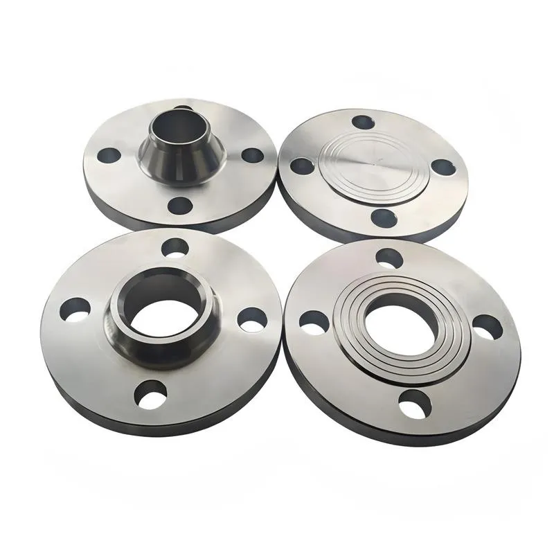
4. **According to Connection Method/Type:** Flanges are classified as follows:
Plate Flat Welding Flange, Necked Flat Welding Flange, Necked Butt Welding Flange, Socket Welding Flange, Threaded Flange, Blind Flange, Necked Butt Welding Ring Loose Flange, Flat Welding Ring Loose Flange, Ring-Type Joint (RTJ) Flange and Blind Flange, Large-Diameter Plate Flange, Large-Diameter High-Neck Flange, Figure-8 Blind Plate, Butt Welding Ring Loose Flange, etc.
5. **According to the Component Being Connected:** Flanges can be classified into Vessel Flanges and Pipe Flanges.
6. **According to Structural Type:** Flanges include Integral Flanges, Threaded Flanges, Flat Welding Flanges, Butt Welding Flanges, Lap Joint (Loose/Swivel) Flanges, and Blind Flanges.
A flange—also referred to as a flange plate or rim—is a component used to connect shafts to one another, or, more commonly, to join the ends of pipes. Flanges are also utilized at the inlet and outlet ports of equipment to facilitate connections between two devices—for instance, the flange on a speed reducer. A "flange connection" or "flanged joint" refers to a detachable joint assembly comprising three interconnected elements—a flange, a gasket, and bolts—that together form a sealed structural unit. In the context of piping systems, a "pipe flange" specifically denotes a flange used for plumbing within the installation; when applied to equipment, it refers to the inlet or outlet flange of that specific device. Flanges feature a series of holes through which bolts are inserted to securely fasten the two flanges together, while a gasket placed between the flanges ensures a leak-proof seal. Flanges are broadly categorized into three types: threaded (screw-in) flanges, welded flanges, and clamp-type flanges. Flanges are invariably used in pairs; threaded flanges are suitable for low-pressure piping applications, whereas welded flanges are required for systems operating at pressures exceeding 4 kilograms per square centimeter. A sealing gasket is inserted between the two flange plates, which are then firmly secured using bolts. The thickness of a flange—as well as the specifications of the bolts used to fasten it—vary depending on the specific pressure rating required for the application. When connecting equipment such as water pumps or valves to piping systems, the corresponding connection points on these devices are often manufactured in the shape of a matching flange; this method of attachment is also referred to as a "flange connection." Generally, any connecting component that utilizes bolts to join and seal the perimeters of two flat surfaces—such as the joints in ventilation ducts—is termed a "flange"; such components may collectively be classified as "flange-type parts." However, since such a connection often constitutes merely a *portion* of a larger device—for instance, the interface between a flange and a water pump—it would be inappropriate to classify the entire water pump itself as a "flange-type part." Conversely, smaller components—such as valves—that feature such flanged interfaces may indeed be appropriately categorized as "flange-type parts."
-:-
For detailed product information, please contact sales.
-:
High Silicon Ductile Iron Flange at RT 4Si-0.5Mo nominal alloy content Product Information
-:-
For detailed product information, please contact sales.
-:
High Silicon Ductile Iron Flange at RT 4Si-0.5Mo nominal alloy content Synonyms
-:-
For detailed product information, please contact sales.
-:
High Silicon Ductile Iron at RT 4Si-0.5Mo nominal alloy content Product Information
-:-
For detailed product information, please contact sales.
-:
### **Product Technical Data Sheet: High Silicon Ductile Iron – RT Series (Nominal 4% Si - 0.5% Mo Alloy)**
---
#### **1. Product Overview**
**High Silicon Ductile Iron (HSDI) with nominal 4% Silicon and 0.5% Molybdenum (4Si-0.5Mo)** is an **advanced, solid-solution and carbide-strengthened ferritic ductile iron** engineered for demanding applications requiring **enhanced elevated temperature strength, creep resistance, and oxidation stability**. This alloy, often referenced in research and development as an **RT-series variant**, strategically combines the **solid solution strengthening of high silicon** with the **precipitation and solid solution hardening of molybdenum**. It is designed to bridge the performance gap between standard ferritic ductile irons and high-alloy austenitic grades, offering a cost-effective solution for components operating under sustained thermal and mechanical stress.
---
#### **2. Governing Standards & Specifications**
This is a performance-optimized engineering alloy, typically governed by proprietary or application-specific specifications.
* **Primary References:**
* **Development/Proprietary Alloys:** Often designated under codes like **RT-4Mo** or grouped within **SiMo ductile iron families** (e.g., analogous to commercial SiMo 4.0-0.5).
* **Industry Framework Standards:** While no direct standard exists for this exact composition, it falls under the broader scope of alloyed ductile irons in:
* **ISO 1083 / EN 1563** (with supplementary alloy requirements).
* **ASTM A536** may be referenced for base ductile iron requirements, with alloy additions as an amendment.
* **Key Testing Standards:** ASTM E8 (Tensile), E21 (Elevated Temperature Tensile), E139 (Creep Test), G54 (Oxidation Resistance).
---
#### **3. Typical Chemical Composition**
The composition is precisely balanced to maximize high-temperature performance without compromising room-temperature integrity.
| Element | Target Range (wt.%) | Critical Role & Rationale |
| :--- | :--- | :--- |
| **Carbon (C)** | 2.8 - 3.3 | **Intentionally lowered.** High Si is a powerful graphitizer; low C prevents excessive carbon equivalent (CE) and graphite flotation, ensuring mechanical soundness. |
| **Silicon (Si)** | **3.8 - 4.2 (Nominal 4.0)** | **Primary Alloy.** Provides **solid solution strengthening** of the ferrite matrix, significantly raises the ferrite-to-austenite transformation temperature (Ac1), and forms a protective, adherent SiO₂ scale for **superior oxidation resistance**. |
| **Molybdenum (Mo)** | **0.4 - 0.6 (Nominal 0.5)** | **Key Additive.** Provides **solid solution strengthening** in ferrite and promotes the formation of fine, stable carbides (e.g., Mo₂C). This significantly **improves high-temperature tensile strength, yield strength, and, most critically, creep resistance** by impeding dislocation climb and grain boundary sliding. |
| **Manganese (Mn)** | **≤ 0.20** | **Very low.** Essential to prevent formation of brittle (Mn,Mo,Si)-rich phases at cell boundaries, which would severely reduce ductility and toughness. |
| **Magnesium (Mg)** | 0.03 - 0.06 | Ensures full nodularity in the alloyed matrix. |
| **Cerium (Ce)/Rare Earths** | Often used | Aids in graphite nodularization and counteracts trace element effects. |
| **Phosphorus (P)** | **≤ 0.03** | **Extremely low.** Critical to avoid severe embrittlement from phosphide networks, exacerbated by high Si and Mo. |
| **Nickel (Ni)** | ≤ 0.50 | May be present incidentally; not a primary addition. |
---
#### **4. Physical & Mechanical Properties**
The 0.5% Mo addition provides a marked improvement in high-temperature capability over the base 4% Si alloy.
| Property | Typical Value (Room Temp) | Elevated Temperature Performance (e.g., 600-700°C / 1112-1292°F) |
| :--- | :--- | :--- |
| **Tensile Strength (UTS)** | **600 - 700 MPa (87 - 102 ksi)** | **Retains ~50-60% of RT UTS** at 700°C, superior to standard and high-Si (no Mo) DI. |
| **Yield Strength (0.2% YS)** | **450 - 550 MPa (65 - 80 ksi)** | **Retains ~55-65% of RT YS** at 700°C. Mo significantly slows yield strength drop-off with temperature. |
| **Elongation** | **8 - 15%** | Ductility remains adequate at RT but decreases at high temperature. |
| **Hardness (HBW)** | 220 - 270 HBW | Increased due to combined Si and Mo strengthening. |
| **Modulus of Elasticity** | ~155 - 165 GPa | Slightly reduced vs. standard DI. |
| **Creep Resistance** | **Good to Very Good** | The 0.5% Mo addition provides a clear improvement in **stress rupture life** and **reduces creep rate** at temperatures up to ~750°C compared to Mo-free high-Si DI. |
| **Oxidation Resistance** | **Excellent** | Comparable to 4% Si alloy. Stable, slow-growing SiO₂-based scale provides protection up to **850-900°C (1562-1652°F)** in oxidizing atmospheres. |
| **Thermal Conductivity** | **~28-33 W/m·K** | Slightly lower than standard DI, but sufficient for many applications. |
| **Thermal Fatigue Resistance** | **Very Good** | Combination of high strength, good ductility, and moderate conductivity resists crack initiation under thermal cycling. |
| **Microstructure** | **100% Ferritic Matrix** with fine **Spheroidal Graphite**. May contain very fine Mo-rich carbides dispersed in the ferrite. |
---
#### **5. Product Applications**
This alloy is targeted at applications where both high temperature and significant mechanical load are present.
* **Turbocharger Housings & Manifolds:** For high-performance and heavy-duty diesel engines, where peak temperatures and pressure cycles demand superior thermal fatigue and creep resistance.
* **Exhaust System Components:** **Manifolds, EGR coolers, and hot ends of exhaust systems** in advanced powertrains.
* **Industrial Heating & Heat Treatment:** **Fixture components, trays, and support structures** in continuous furnaces operating at 700-850°C.
* **Power Generation:** **Components for waste-heat recovery systems, turbine housings**, and other high-temperature energy equipment.
* **Chemical Processing:** **Reactor parts, valve bodies, and pump casings** handling hot, corrosive media.
---
#### **6. Fabrication & Processing Notes**
* **Melting & Casting:** Requires precise control. Mo additions increase hardenability; careful cooling after casting is needed to avoid undesirable carbide networks in heavy sections.
* **Heat Treatment:** Typically used in the **as-cast or subcritically annealed** condition to ensure a fully ferritic matrix and temper any as-cast carbides. **Not suitable for conventional quenching and tempering** due to high Ac1 temperature.
* **Machinability:** **Difficult.** The combination of solid solution strengthening (Si) and fine carbide dispersion (Mo) makes it abrasive and hard. Requires carbide tooling, rigid setups, and optimized parameters.
* **Weldability:** **Extremely Poor.** Highly susceptible to cold cracking and formation of brittle phases in the heat-affected zone (HAZ). **Welding is generally not recommended** for critical components.
---
#### **7. Ordering Information**
**Specify:** **"High Silicon-Molybdenum Ductile Iron Castings, 4Si-0.5Mo Alloy (SiMo-type), As-Cast/Annealed per [Proprietary or Agreed Specification]."**
**Critical Details to Provide:**
* **Exact Compositional Ranges** for Si, Mo, C, and critical residuals (P, Mn).
* **Required Mechanical Properties** at room temperature **and** at specified elevated service temperatures.
* **Application Context & Key Performance Criteria** (e.g., max service temperature, load type - static/cyclic, atmosphere).
* **Certification Requirements:** Full chemical analysis, RT mechanical tests, and ideally elevated temperature test data. Microstructure validation is essential.
* **Special Validation Testing:** May include **creep-rupture testing**, **oxidation weight gain tests**, or **component-level thermal cycling tests**.
**The 4Si-0.5Mo High Silicon Ductile Iron alloy represents a calibrated enhancement for severe service, where the addition of molybdenum provides the necessary mechanical backbone to exploit the full high-temperature potential of the silicon-strengthened ferritic matrix.**
-:-
For detailed product information, please contact sales.
-:
High Silicon Ductile Iron at RT 4Si-0.5Mo nominal alloy content Specification
Dimensions
Size:
Diameter 20-1000 mm Length <6544 mm
Size:We can customized as required
Standard:
Per your request or drawing
We can customized as required
Properties(Theoretical)
Chemical Composition
-:-
For detailed product information, please contact sales.
-:
High Silicon Ductile Iron at RT 4Si-0.5Mo nominal alloy content Properties
-:-
For detailed product information, please contact sales.
-:
Applications of High Silicon Ductile Iron Flange at RT 4Si-0.5Mo nominal alloy content
-:-
For detailed product information, please contact sales.
-:
Chemical Identifiers High Silicon Ductile Iron Flange at RT 4Si-0.5Mo nominal alloy content
-:-
For detailed product information, please contact sales.
-:
Packing of High Silicon Ductile Iron Flange at RT 4Si-0.5Mo nominal alloy content
-:-
For detailed product information, please contact sales.
-:
Standard Packing:
-:-
For detailed product information, please contact sales.
-:
Typical bulk packaging includes palletized plastic 5 gallon/25 kg. pails, fiber and Steel Flange drums to 1 ton super sacks in full container (FCL) or truck load (T/L) quantities. Research and sample quantities and hygroscopic, oxidizing or other air sensitive materials may be packaged under argon or vacuum. Solutions are packaged in polypropylene, plastic or glass jars up to palletized 3015 gallon liquid totes Special package is available on request. E FORUs’ is carefully handled to minimize damage during storage and transportation and to preserve the quality of our products in their original condition