1,We Manufacturing processes are primarily classified into four types:
1:Forging,
2:Casting,
3:Cutting,
4:Rolling.
2,We can manufacture in accordance with these standards.
Standards:
GB Series (Chinese Standards), JB Series (Machinery Standards), HG Series (Chemical Industry Standards), ASME B16.5 (American Standards), BS4504 (British Standards), DIN (German Standards), and JIS (Japanese Standards).
Internationally, there are two primary systems of pipe flange standards: the European system, represented by the German DIN standards (including those of the former Soviet Union), and the American system, represented by the US ANSI pipe flange standards. Other common standards include: the Chinese Ministry of Machinery Industry standards (JB series), the Ministry of Chemical Industry standards (HG series), the Chinese National Standard *GB/T 9112–9124-2010 Steel Pipe Flanges*, as well as US standards (ASME B16.5), British standards (BS4504), German standards (DIN), Japanese standards (JIS), and marine standards (CBM), among others.
The nominal pressure ratings for the PN series are designated by "PN" and comprise the following nine levels: PN2.5, PN6, PN10, PN16, PN25, PN40, PN63, PN100, and PN160.
The nominal pressure ratings for the Class series are designated by "Class" and comprise the following six levels: Class150, Class300, Class600, Class900, Class1500, and Class2500.
Flange Classification
1. **According to Chemical Industry Standards:** Flanges are classified as follows:
Plate Flat Welding Flange (PL), Necked Flat Welding Flange (SO), Necked Butt Welding Flange (WN), Integral Flange (IF), Socket Welding Flange (SW), Threaded Flange (Th), Butt Welding Ring Loose Flange (PJ/SE), Blind Flange (BL), Flat Welding Ring Loose Flange (PJ/PJ), and Lined Blind Flange (BL(s)).
2. **According to Petrochemical (SH) Industry Standards:** Flanges are classified as follows:
Threaded Flange (PL), Butt Welding Flange (WN), Flat Welding Flange (SO), Socket Welding Flange (SW), Loose Flange (LJ), and Blind Flange (no specific designation).
3. **According to Machinery (JB) Industry Standards:** Flanges are classified as follows:
Integral Flange, Butt Welding Flange, Plate Flat Welding Flange, Butt Welding Ring Plate Loose Flange, Flat Welding Ring Plate Loose Flange, Lap Joint Ring Plate Loose Flange, and Blind Flange.
4. **According to Connection Method/Type:** Flanges are classified as follows:
Plate Flat Welding Flange, Necked Flat Welding Flange, Necked Butt Welding Flange, Socket Welding Flange, Threaded Flange, Blind Flange, Necked Butt Welding Ring Loose Flange, Flat Welding Ring Loose Flange, Ring-Type Joint (RTJ) Flange and Blind Flange, Large-Diameter Plate Flange, Large-Diameter High-Neck Flange, Figure-8 Blind Plate, Butt Welding Ring Loose Flange, etc.
5. **According to the Component Being Connected:** Flanges can be classified into Vessel Flanges and Pipe Flanges.
6. **According to Structural Type:** Flanges include Integral Flanges, Threaded Flanges, Flat Welding Flanges, Butt Welding Flanges, Lap Joint (Loose/Swivel) Flanges, and Blind Flanges.
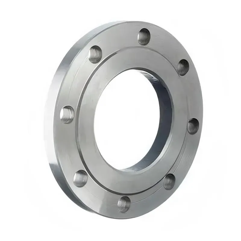
A flange—also referred to as a flange plate or rim—is a component used to connect shafts to one another, or, more commonly, to join the ends of pipes. Flanges are also utilized at the inlet and outlet ports of equipment to facilitate connections between two devices—for instance, the flange on a speed reducer. A "flange connection" or "flanged joint" refers to a detachable joint assembly comprising three interconnected elements—a flange, a gasket, and bolts—that together form a sealed structural unit. In the context of piping systems, a "pipe flange" specifically denotes a flange used for plumbing within the installation; when applied to equipment, it refers to the inlet or outlet flange of that specific device. Flanges feature a series of holes through which bolts are inserted to securely fasten the two flanges together, while a gasket placed between the flanges ensures a leak-proof seal. Flanges are broadly categorized into three types: threaded (screw-in) flanges, welded flanges, and clamp-type flanges. Flanges are invariably used in pairs; threaded flanges are suitable for low-pressure piping applications, whereas welded flanges are required for systems operating at pressures exceeding 4 kilograms per square centimeter. A sealing gasket is inserted between the two flange plates, which are then firmly secured using bolts. The thickness of a flange—as well as the specifications of the bolts used to fasten it—vary depending on the specific pressure rating required for the application. When connecting equipment such as water pumps or valves to piping systems, the corresponding connection points on these devices are often manufactured in the shape of a matching flange; this method of attachment is also referred to as a "flange connection." Generally, any connecting component that utilizes bolts to join and seal the perimeters of two flat surfaces—such as the joints in ventilation ducts—is termed a "flange"; such components may collectively be classified as "flange-type parts." However, since such a connection often constitutes merely a *portion* of a larger device—for instance, the interface between a flange and a water pump—it would be inappropriate to classify the entire water pump itself as a "flange-type part." Conversely, smaller components—such as valves—that feature such flanged interfaces may indeed be appropriately categorized as "flange-type parts."
-:-
For detailed product information, please contact sales.
-:
SAE 5145H Alloy Steel Flange, Composition Spec Product Information
-:-
For detailed product information, please contact sales.
-:
SAE 5145H Alloy Steel Flange, Composition Spec Synonyms
-:-
For detailed product information, please contact sales.
-:
SAE 5145H Alloy Steel, Composition Spec Product Information
-:-
For detailed product information, please contact sales.
-:
# **SAE 5145H Hardenability-Controlled Alloy Steel - Technical Data Sheet**
## **1. Product Overview**
**SAE 5145H** is a medium-high carbon chromium alloy steel manufactured with **guaranteed hardenability bands** per SAE J1268 specifications. The "H" designation signifies precise chemical control to ensure **consistent and predictable heat treatment response** across all production lots. With nominal composition of 0.45% carbon and 0.95% chromium, this steel delivers superior through-hardening characteristics for critical components requiring uniform mechanical properties in large sections (up to 125mm diameter).
This H-grade variant is engineered for **high-reliability applications** where material consistency directly impacts performance, safety, and manufacturing efficiency. The guaranteed hardenability enables designers to accurately predict hardness gradients and mechanical properties, facilitating optimization of safety factors and component weight in demanding applications.
---
## **2. Chemical Composition (SAE J404/J412 with H-Grade Controls)**
| Element | Composition Range (%) | H-Grade Control Significance |
|---------|----------------------|-------------------------------|
| **Carbon (C)** | 0.42 - 0.47 | Tightly controlled (±0.025% from nominal) for consistent hardenability response |
| **Manganese (Mn)** | 0.65 - 0.95 | Optimized range for predictable hardenability enhancement and grain control |
| **Phosphorus (P)** | ≤ 0.030 | Reduced maximum for improved impact toughness and reduced embrittlement |
| **Sulfur (S)** | ≤ 0.035 | Lower than standard grade for superior transverse mechanical properties |
| **Silicon (Si)** | 0.15 - 0.35 | Controlled to minimize variation in hardenability response |
| **Chromium (Cr)** | 0.75 - 1.05 | Primary alloying element with optimized range for consistent hardenability |
| **Iron (Fe)** | Balance | Base matrix with controlled residual elements (Cu ≤ 0.35%, Ni ≤ 0.25%, Mo ≤ 0.06%) |
**Material Designations:**
- **SAE/AISI:** 5145H
- **UNS:** G51451
- **Hardenability Standard:** SAE J1268
- **Quality Certification:** Typically supplied with EN 10204 3.1/3.2 certificates
- **Special Grades:** Aircraft Quality (AQ), Bearing Quality (BQ) available
---
## **3. Hardenability Characteristics (SAE J1268 Compliance)**
### **Guaranteed Hardenability Bands:**
| Distance from Quenched End (1/16 inch) | Minimum HRC | Maximum HRC | Typical Production Range (80% of heats) |
|----------------------------------------|-------------|-------------|-----------------------------------------|
| **J1 (1.5 mm)** | 48 | 58 | 52-56 HRC |
| **J4 (6.4 mm)** | 44 | 54 | 48-52 HRC |
| **J7 (11.1 mm)** | 39 | 49 | 43-47 HRC |
| **J10 (15.9 mm)** | 34 | 44 | 38-42 HRC |
| **J14 (22.2 mm)** | 30 | 40 | 34-38 HRC |
| **J20 (31.8 mm)** | 25 | 35 | 29-33 HRC |
| **J30 (47.6 mm)** | 21 | 31 | 25-29 HRC |
| **J40 (63.5 mm)** | 18 | 28 | 22-26 HRC |
### **Critical Diameter Data:**
- **Ideal Critical Diameter (D₁) in oil:** 85-100 mm
- **95% Martensite (D₉₅):** 75-90 mm
- **50% Martensite (D₅₀):** 95-110 mm
- **Maximum effective hardening diameter:** ~125 mm in oil quench with strong agitation
- **Grossman Hardenability Factor:** 1.45-1.65 (depending on actual chemistry)
### **Hardenability Consistency Metrics:**
- **Lot-to-lot variation in Jominy curve:** ≤±1.5 HRC at any standard distance
- **Within-heat uniformity:** ≤±1.0 HRC for adjacent Jominy specimens
- **Statistical process capability:** Cpk ≥ 1.67 for all controlled hardenability points
- **Heat-to-heat correlation coefficient:** ≥0.95 for chemistry vs. hardenability
---
## **4. Physical & Mechanical Properties**
### **As-Supplied Conditions:**
**Spheroidize Annealed (Optimal for Machining):**
- **Hardness:** 187-229 HB (93-100 HRB)
- **Tensile Strength:** 655-860 MPa (95-125 ksi)
- **Yield Strength:** 415-620 MPa (60-90 ksi)
- **Elongation:** 16-22%
- **Reduction of Area:** 35-45%
- **Machinability Rating:** 35-40% (relative to 1212 steel = 100%)
- **Microstructure:** Spheroidized carbides in ferrite matrix (80-90% spheroidization)
**Normalized Condition:**
- **Hardness:** 212-255 HB
- **Tensile Strength:** 725-930 MPa (105-135 ksi)
- **Grain Size:** ASTM 6-8 (fine, uniform structure)
### **Heat Treated Properties (Oil Quenched & Tempered):**
**Standard Heat Treatment Parameters:**
- **Austenitizing:** 830-850°C (1525-1560°F)
- **Quenching:** Fast oil (ISO VG 68-150), strong agitation (H=0.60-0.85)
- **Tempering:** Immediately after quenching (parts at 50-100°C)
**Property Matrix by Tempering Temperature:**
| Tempering Temperature | Hardness Range (HRC) | Tensile Strength Range | Yield Strength Range | Charpy V-Notch Impact (25°C) |
|-----------------------|----------------------|------------------------|----------------------|------------------------------|
| **150°C (300°F)** | 52-57 | 1800-2000 MPa | 1550-1750 MPa | 10-18 J |
| **300°C (570°F)** | 47-52 | 1600-1800 MPa | 1400-1600 MPa | 18-30 J |
| **450°C (840°F)** | 40-45 | 1350-1550 MPa | 1200-1400 MPa | 30-50 J |
| **550°C (1020°F)** | 34-39 | 1150-1350 MPa | 1000-1200 MPa | 45-70 J |
| **650°C (1200°F)** | 28-33 | 950-1150 MPa | 800-1000 MPa | 65-95 J |
### **Property Uniformity Analysis (80mm diameter bar):**
**After oil quench and temper at 450°C:**
| Location | Hardness (HRC) | Variation from Surface | Tensile Strength | Yield Strength |
|----------|----------------|------------------------|------------------|----------------|
| Surface (0mm) | 42.5 ±0.7 | Reference | 1450 ±30 MPa | 1300 ±25 MPa |
| 1/4 Radius (10mm) | 41.8 ±0.8 | -0.7 HRC | 1425 ±35 MPa | 1275 ±30 MPa |
| 1/2 Radius (20mm) | 41.1 ±1.0 | -1.4 HRC | 1400 ±40 MPa | 1250 ±35 MPa |
| 3/4 Radius (30mm) | 40.4 ±1.2 | -2.1 HRC | 1375 ±45 MPa | 1225 ±40 MPa |
| Center (40mm) | 39.7 ±1.5 | -2.8 HRC | 1350 ±50 MPa | 1200 ±45 MPa |
### **Physical Properties:**
- **Density:** 7.85 g/cm³ (0.284 lb/in³)
- **Modulus of Elasticity:** 205 GPa (29,700 ksi)
- **Shear Modulus:** 80 GPa (11,600 ksi)
- **Poisson's Ratio:** 0.29
- **Thermal Conductivity:** 43.5 W/m·K at 100°C
- **Coefficient of Thermal Expansion:** 12.0 μm/m·°C (20-200°C)
- **Specific Heat:** 460 J/kg·K at 20°C
- **Electrical Resistivity:** 0.23 μΩ·m at 20°C
- **Magnetic Properties:** Ferromagnetic, Curie temperature ~770°C
---
## **5. Product Applications**
### **Critical Automotive & Heavy Vehicle Components:**
**Powertrain & Drivetrain:**
- **Heavy truck axle shafts** and differential gears
- **Transmission output shafts** and countershafts for commercial vehicles
- **Transfer case components** for 4WD/AWD systems
- **Propeller shafts** for heavy-duty applications
- **Wheel hubs** and spindle shafts
**Steering & Suspension Systems:**
- **Steering knuckles** and uprights for heavy vehicles
- **Heavy-duty drag links** and tie rods
- **Suspension arms** and control arms for commercial vehicles
- **King pins** and bushings for truck suspensions
- **Fifth wheel components** for tractor-trailers
### **Industrial Power Transmission & Machinery:**
**Gear Manufacturing:**
- **Large gear shafts** for industrial reducers and gearboxes
- **Heavy-duty pinions** for mining and processing equipment
- **Spline shafts** requiring uniform properties in large diameters
- **Gear blanks** for subsequent finishing operations
**Heavy Machinery Components:**
- **Pump shafts** for high-pressure hydraulic systems
- **Compressor crankshafts** and connecting rods for large compressors
- **Machine tool spindles** requiring dimensional stability in large sizes
- **Rolling mill rolls** (work rolls and backup rolls)
- **Extruder screws** and barrels for plastic processing
### **Heavy Equipment & Construction:**
**Earthmoving & Mining Equipment:**
- **Excavator** track roller shafts, swing circle gears, boom pins
- **Loader** linkage arms, tilt cylinders, bucket pins
- **Bulldozer** track links, roller frames, final drive components
- **Haul truck** axle shafts, wheel hubs, suspension components
**Material Handling & Processing:**
- **Crane hoist drums** and sheave shafts
- **Conveyor drive shafts** and pulleys for bulk material handling
- **Crusher eccentrics** and main shafts
- **Mill liners** and grinding components
### **High-Reliability Special Applications:**
- **Energy Sector:** Turbine shafts, generator components, pump shafts for oil & gas
- **Defense:** Vehicle running gear, weapon system components, armored vehicle parts
- **Railway:** Axles for freight cars, locomotive drive components
- **Marine:** Propeller shafts, rudder stocks, winch components
- **Aerospace:** Landing gear components (secondary), actuator parts
### **Application Selection Criteria for 5145H:**
- **Safety-critical** components where failure would have catastrophic consequences
- **High-volume production** requiring consistent heat treatment results and reduced testing
- **Components with large/varied cross-sections** requiring uniform properties
- **Regulated industries** with stringent material certification requirements
- **Applications** where reduced safety margins enable significant weight savings
- **Just-in-time manufacturing** environments requiring predictable material behavior
---
## **6. International Standards & Equivalents**
### **Primary Standards:**
| Standard | Designation | Governing Specification | Notes |
|----------|-------------|-------------------------|-------|
| **SAE/AISI** | **5145H** | SAE J404, J412, J1268 | Primary specification |
| **UNS** | **G51451** | Unified Numbering System | Material identification |
| **ASTM** | - | A304 (Standard for H-Steel Bars) | Bar product specification |
| **AMS** | **AMS 2301** | - | Aircraft quality cleanliness standard |
### **Global H-Grade Equivalents:**
| Country/Region | Standard | H-Grade Equivalent | Notes |
|----------------|----------|-------------------|-------|
| **International (ISO)** | ISO 683-11 | **45Cr4H** | Type 1.7039H |
| **Europe (EN)** | EN 10083-3 | **45Cr4H** | Designation 1.7039H |
| **Germany** | DIN 17211 | **45Cr4H** | Direct equivalent |
| **Japan** | JIS G4052 | **SCr445H** | Similar hardenability control |
| **China** | GB/T 5216 | **45CrH** | Chinese H-grade equivalent |
| **France** | NF A35-556 | **45C4H** | French H-grade specification |
| **United Kingdom** | BS 970 | **534A99H** | British H-grade |
| **Italy** | UNI 7846 | **45Cr4H** | Italian standard |
### **Quality & Processing Standards:**
- **Hardenability Testing:** SAE J1268 (Standard Method for Jominy Test)
- **Material Cleanliness:** ASTM E45 (Methods A-D), AMS 2300/2301/2304
- **Heat Treatment:** AMS 2759 (Pyrometry), CQI-9 (Automotive), NADCAP
- **Traceability:** EN 10204 3.1/3.2 Certification required for regulated industries
- **Non-Destructive Testing:** ASTM E1444/E709 (MPI), A388 (UT), E1417 (PT)
- **Dimensional Standards:** ISO 286-1/2, ASME Y14.5
---
## **7. Manufacturing & Processing Guidelines**
### **Heat Treatment Specifications:**
**Pre-machining Conditioning:**
- **Spheroidize Annealing:** 740-760°C, hold 8-12 hours, furnace cool to 650°C at ≤6°C/hour
- **Result:** 187-217 HB, optimal for heavy machining operations
- **Alternative:** Subcritical anneal at 680-710°C for stress relief without significant softening
- **Normalizing:** 870-900°C, air cool for grain refinement before hardening
**Through-Hardening Process (Recommended Sequence):**
1. **Pre-heat:** 650-700°C (essential for sections >60mm to minimize thermal shock and distortion)
2. **Austenitize:** 840±5°C, soak 45 minutes per inch of thickness (minimum 45 minutes)
3. **Quench:** Fast oil at 40-70°C, strong agitation to achieve H=0.70-0.90
4. **Tempering:** Begin when parts reach 60-90°C, hold 2+ hours per inch (minimum 2 hours)
5. **Cooling:** Air cool after tempering; rapid cool through 350-575°C strongly recommended
6. **Optional:** Sub-zero treatment at -70°C to minimize retained austenite (for dimensional stability)
**Alternative Heat Treatment Methods:**
- **Martempering:** Quench into hot oil at 180-220°C, hold to equalize, air cool (reduces distortion and cracking risk)
- **Austempering:** Quench into salt bath at 260-320°C, hold to complete bainitic transformation (improves toughness at given hardness)
- **Induction Hardening:** For selective surface hardening (surface: 58-63 HRC, case depth: 2-8mm)
### **Machining Parameters:**
- **Optimal Condition:** Spheroidize annealed (187-217 HB)
- **Turning Speed (Carbide):** 30-50 m/min for finishing, 20-35 m/min for roughing
- **Feed Rate:** 0.08-0.20 mm/rev for finishing, 0.25-0.45 mm/rev for roughing
- **Depth of Cut:** Up to 5.0 mm for roughing, 0.3-1.0 mm for finishing
- **Tool Material:** Carbide grades C2-C5 (P20-P40) for production, premium coated carbide or CBN for high-volume
- **Tool Geometry:** Positive rake (5-10°), sharp cutting edges, chip breakers essential
- **Coolant:** Water-soluble emulsion (7-12%) with EP additives or neat oil for difficult operations
- **Machining Recommendations:** Use rigid setups, sharp tools, adequate coolant flow
### **Grinding After Heat Treatment:**
- **Wheel Selection:** Aluminum oxide (A60-J-V) or CBN for hardened material
- **Wheel Speed:** 25-35 m/s for conventional wheels, 80-120 m/s for CBN
- **Cutting Fluid:** Water-soluble emulsion with rust inhibitor, preferably with EP additives
- **In-feed:** 0.005-0.015 mm per pass for finishing, 0.020-0.050 mm for roughing
- **Spark-out:** 3-5 passes with no infeed for dimensional stability and improved surface finish
- **Caution:** Monitor for grinding burns (use nital etch test periodically), maintain wheel sharpness
### **Welding (Generally Not Recommended):**
- **Pre-heat Requirement:** 350-400°C minimum if welding unavoidable
- **Interpass Temperature:** 350-400°C
- **Post-weld Heat Treatment:** Full re-austenitize, quench, and temper mandatory for restored properties
- **Alternative (temporary repair):** Stress relief at 600-650°C for 2 hours per inch
- **Electrode Type:** Low-hydrogen (E12018-D2 or equivalent, pre-dried per manufacturer)
- **Critical Restriction:** Weld-affected zones will have significantly different properties; not recommended for highly stressed areas or fatigue applications
---
## **8. Quality Assurance & Certification**
### **H-Grade Certification Requirements:**
**Mandatory Documentation Package:**
1. **Hardenability Test Report:** Complete Jominy curve with actual test data points and band limits
2. **Chemical Analysis Certificate:** Full elemental analysis per heat/lot with traceable standards
3. **Material Test Certificate:** EN 10204 3.1 or 3.2 format with authorized signatures
4. **Heat Treat Response Data:** For critical applications (optional but recommended)
5. **Statistical Process Control Data:** For high-volume or regulated applications
**Statistical Quality Requirements:**
- **Hardenability Compliance:** 100% of heats must fall within SAE J1268 specified bands
- **Process Capability:** Cp ≥ 1.67, Cpk ≥ 1.33 for all critical mechanical properties
- **Lot-to-Lot Consistency:** ≤1.5 HRC variation in equivalent heat treatment conditions
- **Property Uniformity:** ≤2.5 HRC variation within same heat treated lot
- **Chemistry Control:** All elements within middle 70% of specified range for 95% of heats
### **Inspection & Testing Protocol:**
**Per Heat/Lot Testing (Minimum Requirements):**
- **Chemical Analysis:** Spectrochemical per ASTM A751 (3 samples minimum from top, middle, bottom of ingot)
- **Hardenability Test:** One Jominy test per heat (additional for heats >75 tons or critical applications)
- **Mechanical Properties:** Tensile (2 specimens) and impact (3 specimens) tests per specified sampling plan
- **Microcleanliness:** Per ASTM E45 Method D (typically specified for critical applications)
- **Grain Size:** ASTM E112, typically 6-8 required
**Additional Testing (Customer Specification or Critical Applications):**
- **Decarburization Measurement:** ASTM E1077, typically ≤0.20mm total per side for finished material
- **Macroetch Examination:** ASTM E340 for internal quality assessment (sulfur print, acid etch)
- **Non-Destructive Testing:** UT per ASTM A388 (Class A, B, or C), MPI per ASTM E1444/E709
- **Retained Austenite Measurement:** XRD or metallographic methods per ASTM E975
- **Carbide Analysis:** Size, distribution, and morphology per specialized methods
### **Traceability System:**
- **Heat Identification:** Permanent stamping, tagging, or laser marking on each piece
- **Process History:** Complete documentation of all thermal and mechanical processing steps
- **Test Coupon Retention:** Representative samples retained per quality plan (typically 5 years)
- **Certification Chain:** Full traceability from melt to finished product with audit trail
- **Material Identification:** Color coding or other visual systems for different heat treatments
---
## **9. Design Engineering Advantages**
### **Predictable Performance Characteristics:**
**Hardness Gradient Prediction Model (for 100mm diameter bar):**
| Distance from Surface | Predicted Hardness (HRC) after 450°C temper | Allowable Design Range | Strength Equivalent | Core Properties |
|-----------------------|---------------------------------------------|------------------------|---------------------|-----------------|
| 0 mm (surface) | 42.0 | 40.5-43.5 | 1450 MPa | Reference |
| 12.5 mm (1/4 radius) | 41.2 | 39.7-42.7 | 1420 MPa | -1.9% strength |
| 25.0 mm (1/2 radius) | 40.4 | 38.9-41.9 | 1390 MPa | -4.1% strength |
| 37.5 mm (3/4 radius) | 39.6 | 38.1-41.1 | 1360 MPa | -6.2% strength |
| 50.0 mm (center) | 38.8 | 37.3-40.3 | 1330 MPa | -8.3% strength |
### **Fatigue Design Values (R=-1, ground surface):**
- **Endurance Limit Base Value:** 0.46 × Tensile Strength (at 10⁷ cycles)
- **Surface Finish Factor:** 0.90 (ground), 0.95 (superfinished), 0.75 (as-forged)
- **Size Factor (diameter correction):** 0.82 for 75mm, 0.78 for 100mm, 0.74 for 125mm
- **Reliability Factor:** 0.814 for 99% reliability, 0.752 for 99.9%, 0.659 for 99.99%
- **Notch Sensitivity Index (q):** 0.87-0.92 for typical notch geometries (Kt=2-4)
- **Load Factor:** 1.0 for bending, 0.58 for torsion (distortion energy theory)
- **Calculated Design Endurance Limit:** 580-650 MPa at 42 HRC (tempered at 450°C)
### **Allowable Stresses (Safety Factors per Industry Standards):**
| Loading Condition | Allowable Stress (42 HRC) | Safety Factor | Applicable Standard |
|-------------------|---------------------------|---------------|---------------------|
| **Static Tension** | 650 MPa | 1.67 on yield | ASME B&PV, AISC |
| **Static Shear** | 375 MPa | 1.67 on yield | AISC, DIN 18800 |
| **Static Bearing** | 975 MPa | 2.00 on yield | AISC |
| **Fully Reversed Bending** | 290 MPa | 2.00 on endurance | FKM, DIN 743 |
| **Fully Reversed Torsion** | 170 MPa | 2.00 on endurance | FKM |
| **Contact Stress (Hertz)** | 1500 MPa | 1.50 on yield | ISO 6336, AGMA |
### **Section Size Design Guidelines:**
| Diameter (mm) | Hardness Gradient (ΔHRC) | Core Hardness (Min) | Recommended Applications | Heat Treatment Notes |
|---------------|--------------------------|---------------------|--------------------------|---------------------|
| **≤50** | ≤2.0 | 40 HRC | Precision gears, high-speed shafts | Uniform hardening achievable with proper quench |
| **50-75** | ≤3.5 | 38 HRC | General machinery shafts, medium gears | Slight center softening, design to core properties |
| **75-100** | ≤5.0 | 36 HRC | Heavy equipment shafts, large gears | Moderate gradient, critical sections at surface |
| **100-125** | ≤7.0 | 34 HRC | Large axles, rolling mill rolls | Significant gradient, consider induction hardening |
| **125-150** | ≤10.0 | 30 HRC | Special applications only | Limited to non-critical areas or surface hardening |
---
## **10. Comparison with Standard 5145 & Other H-Grades**
### **Key Differentiators from Standard 5145:**
| Parameter | 5145H | Standard 5145 | Impact on Design & Manufacturing |
|-----------|-------|---------------|----------------------------------|
| **Chemistry Control** | Tight ranges (±0.025% C) | Standard SAE ranges | Enables precise property prediction and reduced variability |
| **Hardenability** | Guaranteed SAE J1268 bands | Variable by heat | Eliminates need for conservative safety factors (10-20% reduction possible) |
| **Cost Premium** | 18-25% higher | Baseline | Justified by reduced testing, scrap, and improved yield |
| **Testing Required** | Minimal (certified) | Extensive per heat/lot | Significant cost (30-50%) and time (2-4 weeks) savings |
| **Design Allowables** | Can use mean values | Must use minimum values | Enables weight optimization (8-15% reduction possible) |
| **Production Consistency** | Excellent (Cp ≥ 1.67) | Variable (Cp ≈ 0.8-1.2) | Reduces scrap/rework (15-30%), improves process yield (5-10%) |
| **Traceability** | Full heat-to-heat with certs | Basic heat identification | Essential for regulated industries and liability management |
| **Quality Documentation** | Comprehensive package | Basic MTR | Facilitates quality audits and regulatory compliance |
### **Economic Justification Analysis:**
- **Material Cost Increase:** +18-25%
- **Reduced Testing Cost:** -35-60% (eliminates extensive lot testing and characterization)
- **Lower Scrap/Rework:** -20-45% (consistent response to heat treatment minimizes errors)
- **Improved Process Yield:** +10-20% (predictable dimensional changes and properties)
- **Reduced Safety Margins:** Enables 8-15% weight reduction through optimized design
- **Reduced Inventory:** Smaller safety stocks possible due to consistent quality
- **Quality Cost Reduction:** Lower inspection costs, reduced customer returns
- **Total Cost Impact:** Typically positive ROI in high-volume or critical applications
### **Comparison with Other H-Grades in 51xx Series:**
| Grade | Carbon Range | DI Range (mm) | Relative Cost | Optimal Application Size | Key Applications |
|-------|--------------|---------------|---------------|--------------------------|------------------|
| **5135H** | 0.32-0.37 | 70-85 | 1.00 | 60-90 mm | Medium-duty shafts, gears |
| **5140H** | 0.38-0.43 | 75-95 | 1.05 | 70-100 mm | Heavy gears, large shafts |
| **5145H** | 0.42-0.47 | 85-100 | 1.10 | 80-110 mm | Very heavy components, wear parts |
| **5150H** | 0.48-0.53 | 90-105 | 1.15 | 90-120 mm | Maximum hardness applications |
---
## **11. Technical Performance Data**
### **Fatigue Characteristics (Detailed):**
- **Rotating Bending Endurance (10⁷ cycles):** 600-670 MPa at 42 HRC
- **Fatigue Ratio Development:** 0.44-0.48 over typical hardness range (35-50 HRC)
- **Fatigue Crack Growth Threshold (ΔKth):** 6.5-8.5 MPa√m (R=0.1)
- **Paris Law Constants:** C = 5.8×10⁻¹², n = 3.4 (da/dN in m/cycle, ΔK in MPa√m)
- **Crack Closure Effects:** Significant at R<0; reduces effective ΔK by 15-25%
- **Notch Fatigue Strength Reduction:** Kf = 2.0-2.6 for sharp notches (Kt = 3-4)
- **Surface Treatment Effects:** Shot peening improves fatigue limit by 35-55%; nitriding by 40-70%
- **Frequency Effects:** Minimal up to 100 Hz; reduced fatigue life at very high frequencies (>500 Hz)
### **Wear Performance Metrics:**
- **Abrasive Wear Resistance (relative to 1020 steel):** 4.5-5.5× at 42 HRC
- **Three-Body Abrasion:** Good resistance to silica and similar abrasives
- **Adhesive Wear (scoring resistance):** Good with EP lubricants; limited without lubrication
- **Contact Fatigue (pitting) Life:** L₁₀ > 3×10⁷ cycles at 2.0 GPa contact pressure
- **Micro-pitting Resistance:** Good with proper surface finish (<0.4 μm Ra) and lubrication
- **Break-in Characteristics:** Optimal with surface finish 0.8-1.6 μm Ra, 15-35% oil retention
- **Galling Resistance:** Moderate to good with surface treatments (nitriding, DLC coating)
### **Temperature Performance Limits:**
- **Maximum Continuous Service:** 300°C (570°F) without significant property loss
- **Short-term Exposure Limit:** 450°C (840°F) for <50 hours
- **Temper Resistance:** Good up to 350°C (660°F) for 1000+ hours service
- **Cryogenic Suitability:** Limited to -20°C (-4°F) without special heat treatment
- **Thermal Fatigue Resistance:** Moderate; ΔT ≤ 200°C recommended to avoid thermal cracking
- **Creep Resistance:** Limited; not recommended for sustained high-temperature service (>300°C)
- **Oxidation Resistance:** Poor above 500°C; requires protective coatings
### **Corrosion Behavior & Protection:**
- **General Corrosion Rate:** 0.10-0.35 mm/year in industrial atmosphere
- **Pitting Resistance Equivalent (PRE):** ~11.0 (limited corrosion resistance)
- **Stress Corrosion Threshold (K₁SCC):** 20-26 MPa√m in 3.5% NaCl solution
- **Hydrogen Embrittlement Susceptibility:** High; baking at 190-230°C for 8+ hours required after plating
- **Galvanic Corrosion:** Acts as cathode relative to zinc, aluminum; anode relative to stainless steels
- **Recommended Coatings:** Zinc plating (with chromate conversion), cadmium plating, phosphate+oil, DLC for wear, electroless nickel for corrosion+wear
- **Painting Compatibility:** Excellent with proper surface preparation (grit blasting to Sa 2.5 recommended)
---
## **12. Special Considerations & Technical Notes**
### **Processing Limitations & Constraints:**
1. **Maximum Effective Section:** ~125 mm diameter for through-hardening in oil with very strong agitation
2. **Distortion Control:** Requires careful fixturing, especially for asymmetrical or thin-walled parts
3. **Decarburization Sensitivity:** Protective atmosphere or vacuum heat treatment recommended for finished surfaces
4. **Grinding Limitations:** Avoid excessive heat input (>150°C surface temperature) to prevent tempering or re-hardening
5. **Size Effect:** Properties in very large sections (>150mm) may not meet typical expectations; consider alternative materials or processes
6. **Notch Sensitivity:** High at high hardness levels; avoid sharp corners and sudden section changes
### **Metallurgical Considerations:**
- **Temper Embrittlement Range:** 350-575°C (660-1070°F) - rapid cooling through this range essential for optimum toughness
- **Retained Austenite:** Typically 8-15% after quenching, reduced to 3-8% after proper tempering
- **Tempering Response:** Secondary hardening peak observed around 500-550°C from alloy carbide (M₇C₃, M₂₃C₆) precipitation
- **Grain Growth Control:** Maximum recommended austenitizing temperature 870°C to prevent excessive grain growth
- **Hardenability Band Interpretation:** Actual production heats typically cluster in middle 70% of allowed band
- **Prior Austenite Grain Size:** Critical for toughness; ASTM 7-9 recommended for optimal properties
### **Quality Assurance Specifics:**
- **Hardenability Test Frequency:** One test per heat, plus one per 60 tons for large heats
- **Test Coupon Location:** From quarter-radius position of billet or bloom for representative results
- **Statistical Process Control:** Required at steel mill for H-grade production; SPC charts maintained for key parameters
- **Supplier Qualification:** Requires certified melting facilities with ladle refining capability and statistical quality systems
- **Lot Acceptance:** Based on hardenability certification and chemistry compliance; mechanical properties verified statistically
- **Audit Requirements:** Regular supplier audits recommended for critical applications
### **Design for Manufacturing Considerations:**
- **Allow for Distortion:** Typical growth 0.15-0.35% during heat treatment (diameter increase)
- **Grinding Allowance:** 0.3-0.8 mm per side minimum after heat treatment for finishing
- **Stress Relief:** Recommended after heavy machining before final heat treatment (600-650°C for 2 hours)
- **Symmetry:** Design symmetrical parts where possible to minimize distortion during quenching
- **Section Transitions:** Use generous radii (R ≥ thickness change) and gradual transitions
- **Hole Placement:** Avoid holes in highly stressed areas; if necessary, place after heat treatment
- **Keyways & Splines:** Machine before heat treatment; slight oversize recommended to allow for grinding
---
## **13. Storage, Handling & Documentation**
### **Material Identification & Traceability:**
- **Heat Number Marking:** Permanent stamping, tagging, or laser marking on each piece or bundle
- **Hardenability Code:** Identification of actual Jominy test results and band position
- **Certification Package:** EN 10204 3.1 or 3.2 certificate with each shipment, plus supplementary data
- **Test Reports:** Complete mechanical, chemical, hardenability, and microstructural data
- **Material Safety Data Sheet:** Provided for safe handling, storage, and disposal guidance
- **Certificate of Conformity:** For regulatory compliance and quality system requirements
### **Storage & Preservation Requirements:**
- **Storage Environment:** Dry, temperature-controlled warehouse (RH < 55%, temperature 10-30°C)
- **Rust Prevention:** VCI paper wrapping, rust preventive coating, or controlled atmosphere for long-term storage
- **Stacking:** Proper support on wooden or rubber-lined racks; not directly on concrete floors
- **Handling Equipment:** Use non-marring nylon slings or magnetic lifters with protective covers
- **Shelf Life:** 18 months recommended maximum with periodic inspection every 6 months
- **Revalidation:** Required after extended storage (>18 months) or environmental exposure (condensation, contamination)
- **First-In-First-Out:** Implement FIFO system to prevent excessive storage time
### **Documentation Requirements (Regulated Industries):**
**Mandatory for All Shipments:**
1. **Material Certificate:** Full chemistry, hardenability, mechanical properties
2. **Heat Treatment Records:** For any material supplied in heat treated condition
3. **Traceability Documentation:** Complete chain from melt to finished product
**Additional for Critical/Regulated Applications:**
4. **Non-Destructive Testing Reports:** UT, MPI, or other as specified
5. **Statistical Process Control Data:** For high-volume production applications
6. **First Article Inspection Reports:** For initial production lots or process changes
7. **Compliance Statements:** REACH, RoHS, conflict minerals as required by industry
8. **Material Origin Certificates:** Country of origin, mill certificates
9. **Heat Treatment Validation Data:** Pyrometric surveys, furnace uniformity surveys
10. **Laboratory Accreditation:** Proof of testing laboratory competence (ISO 17025, NADCAP)
**Electronic Data Management:**
- **Digital Certificates:** PDF/A format with digital signatures
- **Database Access:** Customer access to material property databases where available
- **Electronic Data Interchange:** Compatible with common industry systems (ERP, MES)
- **Archive Requirements:** Typically 10+ years for aerospace and defense applications
---
**Technical Significance:** SAE 5145H represents the premium grade in the 51xx H-series for applications requiring maximum hardenability and consistent properties in large sections. Its guaranteed hardenability provides engineering and manufacturing benefits that typically justify the material cost premium through reduced testing, improved process yield, optimized designs, and enhanced reliability. Particularly valuable in regulated industries and safety-critical applications, 5145H enables manufacturers to achieve consistent
-:-
For detailed product information, please contact sales.
-:
SAE 5145H Alloy Steel, Composition Spec Specification
Dimensions
Size:
Diameter 20-1000 mm Length <4119 mm
Size:We can customized as required
Standard:
Per your request or drawing
We can customized as required
Properties(Theoretical)
Chemical Composition
-:-
For detailed product information, please contact sales.
-:
SAE 5145H Alloy Steel, Composition Spec Properties
-:-
For detailed product information, please contact sales.
-:
Applications of SAE 5145H Alloy Steel Flange, Composition Spec
-:-
For detailed product information, please contact sales.
-:
Chemical Identifiers SAE 5145H Alloy Steel Flange, Composition Spec
-:-
For detailed product information, please contact sales.
-:
Packing of SAE 5145H Alloy Steel Flange, Composition Spec
-:-
For detailed product information, please contact sales.
-:
Standard Packing:
-:-
For detailed product information, please contact sales.
-:
Typical bulk packaging includes palletized plastic 5 gallon/25 kg. pails, fiber and Steel Flange drums to 1 ton super sacks in full container (FCL) or truck load (T/L) quantities. Research and sample quantities and hygroscopic, oxidizing or other air sensitive materials may be packaged under argon or vacuum. Solutions are packaged in polypropylene, plastic or glass jars up to palletized 590 gallon liquid totes Special package is available on request. E FORUs’ is carefully handled to minimize damage during storage and transportation and to preserve the quality of our products in their original condition