1,We Manufacturing processes are primarily classified into four types:
1:Forging,
2:Casting,
3:Cutting,
4:Rolling.
2,We can manufacture in accordance with these standards.
Standards:
GB Series (Chinese Standards), JB Series (Machinery Standards), HG Series (Chemical Industry Standards), ASME B16.5 (American Standards), BS4504 (British Standards), DIN (German Standards), and JIS (Japanese Standards).
Internationally, there are two primary systems of pipe flange standards: the European system, represented by the German DIN standards (including those of the former Soviet Union), and the American system, represented by the US ANSI pipe flange standards. Other common standards include: the Chinese Ministry of Machinery Industry standards (JB series), the Ministry of Chemical Industry standards (HG series), the Chinese National Standard *GB/T 9112–9124-2010 Steel Pipe Flanges*, as well as US standards (ASME B16.5), British standards (BS4504), German standards (DIN), Japanese standards (JIS), and marine standards (CBM), among others.
The nominal pressure ratings for the PN series are designated by "PN" and comprise the following nine levels: PN2.5, PN6, PN10, PN16, PN25, PN40, PN63, PN100, and PN160.
The nominal pressure ratings for the Class series are designated by "Class" and comprise the following six levels: Class150, Class300, Class600, Class900, Class1500, and Class2500.
Flange Classification
1. **According to Chemical Industry Standards:** Flanges are classified as follows:
Plate Flat Welding Flange (PL), Necked Flat Welding Flange (SO), Necked Butt Welding Flange (WN), Integral Flange (IF), Socket Welding Flange (SW), Threaded Flange (Th), Butt Welding Ring Loose Flange (PJ/SE), Blind Flange (BL), Flat Welding Ring Loose Flange (PJ/PJ), and Lined Blind Flange (BL(s)).
2. **According to Petrochemical (SH) Industry Standards:** Flanges are classified as follows:
Threaded Flange (PL), Butt Welding Flange (WN), Flat Welding Flange (SO), Socket Welding Flange (SW), Loose Flange (LJ), and Blind Flange (no specific designation).
3. **According to Machinery (JB) Industry Standards:** Flanges are classified as follows:
Integral Flange, Butt Welding Flange, Plate Flat Welding Flange, Butt Welding Ring Plate Loose Flange, Flat Welding Ring Plate Loose Flange, Lap Joint Ring Plate Loose Flange, and Blind Flange.
4. **According to Connection Method/Type:** Flanges are classified as follows:
Plate Flat Welding Flange, Necked Flat Welding Flange, Necked Butt Welding Flange, Socket Welding Flange, Threaded Flange, Blind Flange, Necked Butt Welding Ring Loose Flange, Flat Welding Ring Loose Flange, Ring-Type Joint (RTJ) Flange and Blind Flange, Large-Diameter Plate Flange, Large-Diameter High-Neck Flange, Figure-8 Blind Plate, Butt Welding Ring Loose Flange, etc.
5. **According to the Component Being Connected:** Flanges can be classified into Vessel Flanges and Pipe Flanges.
6. **According to Structural Type:** Flanges include Integral Flanges, Threaded Flanges, Flat Welding Flanges, Butt Welding Flanges, Lap Joint (Loose/Swivel) Flanges, and Blind Flanges.
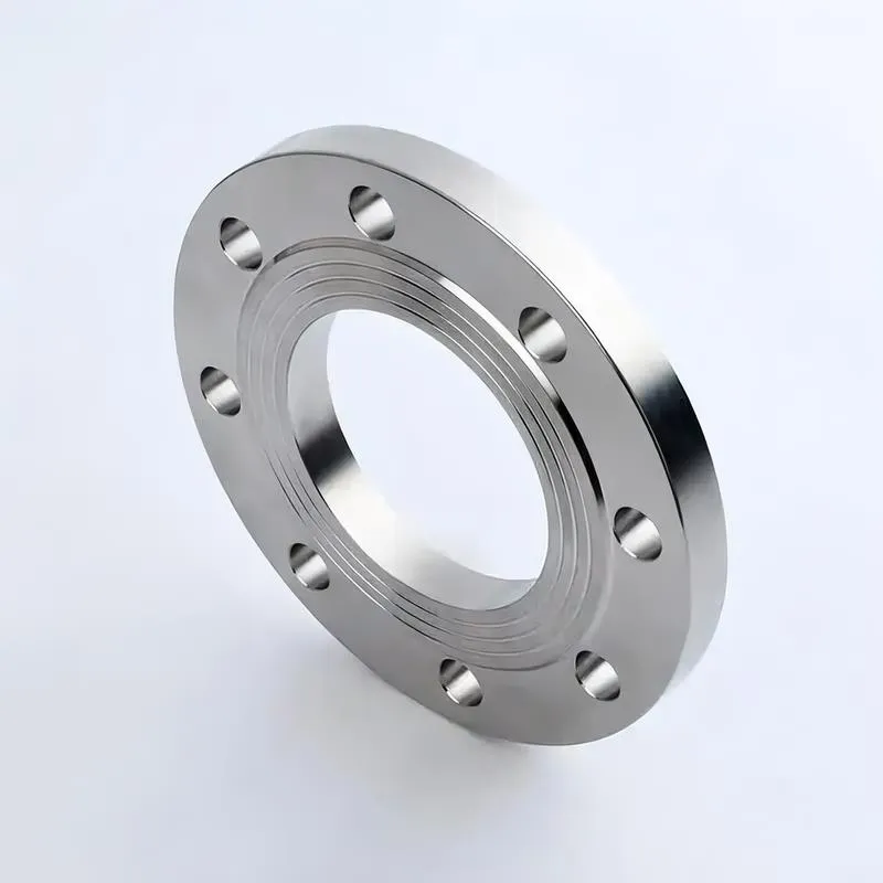
A flange—also referred to as a flange plate or rim—is a component used to connect shafts to one another, or, more commonly, to join the ends of pipes. Flanges are also utilized at the inlet and outlet ports of equipment to facilitate connections between two devices—for instance, the flange on a speed reducer. A "flange connection" or "flanged joint" refers to a detachable joint assembly comprising three interconnected elements—a flange, a gasket, and bolts—that together form a sealed structural unit. In the context of piping systems, a "pipe flange" specifically denotes a flange used for plumbing within the installation; when applied to equipment, it refers to the inlet or outlet flange of that specific device. Flanges feature a series of holes through which bolts are inserted to securely fasten the two flanges together, while a gasket placed between the flanges ensures a leak-proof seal. Flanges are broadly categorized into three types: threaded (screw-in) flanges, welded flanges, and clamp-type flanges. Flanges are invariably used in pairs; threaded flanges are suitable for low-pressure piping applications, whereas welded flanges are required for systems operating at pressures exceeding 4 kilograms per square centimeter. A sealing gasket is inserted between the two flange plates, which are then firmly secured using bolts. The thickness of a flange—as well as the specifications of the bolts used to fasten it—vary depending on the specific pressure rating required for the application. When connecting equipment such as water pumps or valves to piping systems, the corresponding connection points on these devices are often manufactured in the shape of a matching flange; this method of attachment is also referred to as a "flange connection." Generally, any connecting component that utilizes bolts to join and seal the perimeters of two flat surfaces—such as the joints in ventilation ducts—is termed a "flange"; such components may collectively be classified as "flange-type parts." However, since such a connection often constitutes merely a *portion* of a larger device—for instance, the interface between a flange and a water pump—it would be inappropriate to classify the entire water pump itself as a "flange-type part." Conversely, smaller components—such as valves—that feature such flanged interfaces may indeed be appropriately categorized as "flange-type parts."
-:-
For detailed product information, please contact sales.
-:
AISI 4142 Steel Flange, Annealed and Cold Drawn Product Information
-:-
For detailed product information, please contact sales.
-:
AISI 4142 Steel Flange, Annealed and Cold Drawn Synonyms
-:-
For detailed product information, please contact sales.
-:
AISI 4142 Steel, Annealed and Cold Drawn Product Information
-:-
For detailed product information, please contact sales.
-:
# **AISI 4142 Steel - Annealed and Cold Drawn Product Specification**
## **1. Product Definition & Processing History**
This specification covers **AISI 4142** alloy steel supplied as **cold drawn round bars** that have been processed through a specific sequence to achieve optimal mechanical properties and dimensional accuracy.
**Manufacturing Sequence:**
1. **Initial Condition:** Hot-rolled bar stock
2. **Annealing:** Full annealing for microstructure refinement and stress relief
3. **Cold Drawing:** Reduction in diameter through cold working at room temperature
4. **Final Condition:** Annealed and cold drawn (A/CD) with improved surface finish, dimensional accuracy, and enhanced mechanical properties
The combination of annealing and cold drawing produces a material with superior surface characteristics, tighter tolerances, and increased strength compared to hot-rolled or simply annealed material.
## **2. International Standards & Designations**
- **Primary Standard:** ASTM A29/A29M (Standard Specification for Steel Bars, Carbon and Alloy, Hot-Wrought and Cold-Finished)
- **Material Designation:** AISI 4142
- **Condition Designation:** Annealed and Cold Drawn (A/CD)
- **UNS Designation:** G41420
- **European Equivalent:** 1.7227 (42CrMo4 with higher carbon) per EN 10083-3
- **Japanese Equivalent:** SCM440H (modified) per JIS G4105
- **Chinese Equivalent:** 42CrMoA (modified) per GB/T 3077
- **ISO Equivalent:** 42CrMo4+ (ISO 683-18 with adjusted carbon range)
## **3. Chemical Composition (Weight %)**
| Element | Composition Range (%) | Typical Aim (%) | Function in 4142 |
|---------|----------------------|-----------------|------------------|
| **Carbon (C)** | 0.40 - 0.45 | 0.42 | Higher carbon than 4140 for increased strength and hardenability |
| **Manganese (Mn)** | 0.75 - 1.00 | 0.85 | Increases hardenability, strength, and improves response to cold working |
| **Phosphorus (P)** | ≤ 0.035 | 0.020 | Residual element (controlled) |
| **Sulfur (S)** | ≤ 0.040 | 0.025 | Improves machinability (controlled), may be enhanced for free-machining variants |
| **Silicon (Si)** | 0.15 - 0.35 | 0.25 | Deoxidizer, solid solution strengthener |
| **Chromium (Cr)** | 0.80 - 1.10 | 0.95 | Enhances hardenability, wear resistance, and corrosion resistance |
| **Molybdenum (Mo)** | 0.15 - 0.25 | 0.20 | Increases hardenability, high-temperature strength, reduces temper embrittlement |
**Note:** The slightly higher carbon content (0.40-0.45% vs. 4140's 0.38-0.43%) provides greater strength potential, particularly beneficial in the cold drawn condition.
## **4. Physical Properties (Annealed & Cold Drawn Condition)**
- **Density:** 7.85 g/cm³ (0.284 lb/in³)
- **Melting Range:** 1410-1515°C (2570-2760°F)
- **Modulus of Elasticity:** 205 GPa (29.7 × 10⁶ psi) *increased slightly by cold work*
- **Shear Modulus:** 80 GPa (11.6 × 10⁶ psi)
- **Poisson's Ratio:** 0.29
- **Thermal Conductivity:** 41.8 W/m·K at 100°C
- **Specific Heat Capacity:** 460 J/kg·K at 20°C
- **Coefficient of Thermal Expansion:** 11.7 µm/m·°C (20-100°C)
- **Electrical Resistivity:** 0.23 µΩ·m at 20°C
- **Magnetic Properties:** Ferromagnetic
## **5. Mechanical Properties (Annealed & Cold Drawn)**
*Typical guaranteed properties for cold drawn rounds:*
| Property | Value | Notes |
|----------|-------|-------|
| **Tensile Strength** | 860-1030 MPa (125-150 ksi) | 25-40% higher than annealed-only condition |
| **Yield Strength (0.2% offset)** | 690-860 MPa (100-125 ksi) | Significantly increased by cold working |
| **Elongation in 50 mm (2 in.)** | 12-18% | Reduced from annealed due to cold work |
| **Reduction of Area** | 40-50% | - |
| **Hardness (Brinell)** | 255-302 HB | Increased from ~207 HB for annealed-only |
| **Hardness (Rockwell)** | 25-32 HRC | Corresponds to 255-302 HB |
| **Hardness (typical)** | 285 HB / 29 HRC (typical) | - |
| **Impact Energy (Charpy V-notch)** | 27-41 J (20-30 ft-lb) at 20°C | Reduced toughness due to cold work |
**Effect of Cold Drawing:**
- **Strength Increase:** Cold drawing typically increases yield strength by 30-50% compared to annealed condition
- **Work Hardening:** Material exhibits work hardening during drawing, with hardness increasing with greater reduction ratios
- **Anisotropy:** Properties may show slight directional characteristics (higher longitudinal vs. transverse properties)
## **6. Metallurgical Characteristics**
- **Microstructure:** Fine ferrite-pearlite structure with elongated grains in drawing direction
- **Grain Flow:** Characteristic "grain flow" lines parallel to drawing direction
- **Surface Condition:** Superior to hot-rolled with typical roughness (Ra) of 1.6-3.2 µm (63-125 µin)
- **Decarburization:** ≤ 0.13 mm (0.005 in.) total depth - significantly less than hot-rolled due to cold working
- **Dimensional Accuracy:** Superior to hot-rolled material
- **Residual Stress:** Moderate compressive stress at surface, tensile stress in core (balanced condition)
## **7. Manufacturing & Processing Characteristics**
### **Cold Drawing Process Effects**
- **Reduction Ratio:** Typically 10-30% area reduction during drawing
- **Surface Enhancement:** Removes scale and surface imperfections
- **Size Control:** Produces precise diameters with tight tolerances
- **Straightness:** Improved straightness compared to hot-rolled stock
### **Machinability**
- **Relative Machinability:** 60% (compared to 100% for B1112 steel)
- **Machinability Rating:** Fair - harder than annealed-only but with better chip breaking
- **Recommended Cutting Speeds:**
- Turning: 25-40 m/min (80-130 ft/min) with carbide tools
- Drilling: 15-22 m/min (50-72 ft/min) with HSS drills
- Tapping: Use premium taps with appropriate coatings
- **Tool Material:** Carbide recommended, especially for production runs
- **Chip Formation:** Produces shorter chips than fully annealed material
- **Coolant:** Essential for heat dissipation and extended tool life
### **Further Processing Compatibility**
- **Stress Relieving:** Recommended (205-315°C/400-600°F for 1-2 hours) for critical machining to prevent distortion
- **Subsequent Heat Treatment:** Can be quenched and tempered to higher strengths (requires annealing or normalizing first to relieve cold work effects)
- **Weldability:** Poor in cold worked condition - must be annealed before welding
- **Cold Forming:** Limited due to already cold worked state - may require intermediate annealing
- **Surface Hardening:** Suitable after stress relief or annealing
## **8. Dimensional Specifications**
*For cold drawn rounds (typical commercial tolerances):*
- **Diameter Tolerance:** ±0.05 mm to ±0.13 mm (±0.002" to ±0.005") depending on diameter
- **Out-of-Roundness:** ≤ 0.05 mm (0.002") for diameters up to 25 mm
- **Straightness:** ≤ 0.4 mm/m (0.005 in./ft)
- **Surface Finish:** 1.6-3.2 µm Ra (63-125 µin Ra)
- **Standard Diameters:** 3 mm to 100 mm (0.125" to 4.0") commonly available
- **Lengths:** Standard random lengths 3-6 m (10-20 ft), cut lengths available
## **9. Product Applications**
This annealed and cold drawn 4142 product is particularly suitable for:
### **Precision Components**
- **Shafts and axles** requiring minimal machining and good straightness
- **Pivot pins and bushings**
- **Hydraulic cylinder rods** (often hard chrome plated after machining)
- **Linear motion components**
- **Guide rods and columns**
### **Automotive & Transportation**
- **Steering components** (tie rods, drag links)
- **Suspension pins and bushings**
- **Transmission shafts**
- **Axle components**
- **High-strength fasteners** (in this condition or before final heat treatment)
### **Industrial Machinery**
- **Spindles and arbors**
- **Guide rails**
- **Machine tool components**
- **Textile machinery parts**
- **Printing press components**
### **Oil & Gas Equipment**
- **Valve stems and shafts**
- **Pump rods**
- **Measurement while drilling (MWD) tool components**
### **Agricultural Equipment**
- **Implement pins**
- **Hydraulic cylinder rods**
- **Linkage components**
## **10. Advantages of Annealed & Cold Drawn Condition**
1. **Enhanced Mechanical Properties:** Higher strength and hardness compared to annealed-only material
2. **Superior Surface Finish:** Smooth surface ideal for plating, coating, or direct use
3. **Excellent Dimensional Accuracy:** Tight tolerances reduce machining allowance
4. **Improved Straightness:** Better straightness than hot-rolled material
5. **Minimal Decarburization:** Cold drawing removes decarburized surface layer
6. **Good Machinability:** Despite higher hardness, often machines well with proper techniques
7. **Reduced Scale:** No heavy mill scale, reducing cleaning operations
8. **Cost Efficiency:** Often more economical than machining from oversized hot-rolled stock
## **11. Limitations & Considerations**
1. **Directional Properties:** Anisotropic behavior due to cold working
2. **Residual Stress:** May cause distortion during machining if not stress relieved
3. **Reduced Toughness:** Impact resistance lower than annealed condition
4. **Limited Further Cold Work:** Additional cold forming may require annealing
5. **Weldability:** Poor in as-drawn condition
## **12. Quality Assurance**
- **Mill Certification:** Provided with each shipment including chemical analysis and mechanical properties
- **Dimensional Inspection:** 100% dimensional verification for critical applications available
- **Surface Inspection:** Visual and non-destructive testing options
- **Traceability:** Full heat/lot traceability maintained
- **Testing:** Mechanical testing per ASTM A370, dimensional per ASTM A29
- **Certifications:** Can be supplied with EN 10204 3.1/3.2 certifications
## **13. Storage & Handling**
- **Storage:** Dry, indoor environment on padded racks
- **Protection:** Typically oiled or coated with rust preventive
- **Handling:** Use non-marring lifting equipment to prevent surface damage
- **Identification:** Clearly marked with heat number, grade, and size
- **Shelf Life:** 12+ months with proper storage and protection
## **14. Comparison with Other Conditions**
| Condition | Tensile Strength | Yield Strength | Machinability | Cost | Typical Use |
|-----------|-----------------|----------------|---------------|------|-------------|
| **Hot-Rolled** | 655-795 MPa | 415 MPa min | Fair | Lowest | General purpose, forging stock |
| **Annealed Only** | 655-795 MPa | 415 MPa min | Good | Low | Machining before heat treatment |
| **Annealed & Cold Drawn** | 860-1030 MPa | 690-860 MPa | Fair-Good | Medium | Precision parts, shafts, rods |
| **Quenched & Tempered** | 1030-1380 MPa | 930-1240 MPa | Poor | High | High-strength components |
## **15. Technical Notes**
1. **Cold Drawing Effect:** The yield strength increase from cold drawing follows approximately: ΔYS ≈ K × εⁿ, where ε is true strain from drawing
2. **Stress Relief:** For precision components, stress relieve at 260-315°C (500-600°F) for 1 hour per inch of thickness after rough machining
3. **Heat Treatment:** If final heat treatment is required, first normalize at 870-900°C (1600-1650°F) to eliminate cold work effects before quenching and tempering
4. **Size Limitations:** Maximum diameter for effective cold drawing is typically 100-150 mm (4-6 inches)
5. **Alternative:** For larger diameters or when weldability is required, consider annealed-only or normalized material
---
**Disclaimer:** This specification is for informational purposes. Actual properties may vary based on manufacturer, specific drawing process parameters, and testing methods. For critical applications, consult with the material supplier and conduct appropriate qualification testing. Final material selection should be based on specific application requirements and engineering analysis.
-:-
For detailed product information, please contact sales.
-:
AISI 4142 Steel, Annealed and Cold Drawn Specification
Dimensions
Size:
Diameter 20-1000 mm Length <4041 mm
Size:We can customized as required
Standard:
Per your request or drawing
We can customized as required
Properties(Theoretical)
Chemical Composition
-:-
For detailed product information, please contact sales.
-:
AISI 4142 Steel, Annealed and Cold Drawn Properties
-:-
For detailed product information, please contact sales.
-:
Applications of AISI 4142 Steel Flange, Annealed and Cold Drawn
-:-
For detailed product information, please contact sales.
-:
Chemical Identifiers AISI 4142 Steel Flange, Annealed and Cold Drawn
-:-
For detailed product information, please contact sales.
-:
Packing of AISI 4142 Steel Flange, Annealed and Cold Drawn
-:-
For detailed product information, please contact sales.
-:
Standard Packing:
-:-
For detailed product information, please contact sales.
-:
Typical bulk packaging includes palletized plastic 5 gallon/25 kg. pails, fiber and Steel Flange drums to 1 ton super sacks in full container (FCL) or truck load (T/L) quantities. Research and sample quantities and hygroscopic, oxidizing or other air sensitive materials may be packaged under argon or vacuum. Solutions are packaged in polypropylene, plastic or glass jars up to palletized 512 gallon liquid totes Special package is available on request. E FORUs’ is carefully handled to minimize damage during storage and transportation and to preserve the quality of our products in their original condition