1,We Manufacturing processes are primarily classified into four types:
1:Forging,
2:Casting,
3:Cutting,
4:Rolling.
2,We can manufacture in accordance with these standards.
Standards:
GB Series (Chinese Standards), JB Series (Machinery Standards), HG Series (Chemical Industry Standards), ASME B16.5 (American Standards), BS4504 (British Standards), DIN (German Standards), and JIS (Japanese Standards).
Internationally, there are two primary systems of pipe flange standards: the European system, represented by the German DIN standards (including those of the former Soviet Union), and the American system, represented by the US ANSI pipe flange standards. Other common standards include: the Chinese Ministry of Machinery Industry standards (JB series), the Ministry of Chemical Industry standards (HG series), the Chinese National Standard *GB/T 9112–9124-2010 Steel Pipe Flanges*, as well as US standards (ASME B16.5), British standards (BS4504), German standards (DIN), Japanese standards (JIS), and marine standards (CBM), among others.
The nominal pressure ratings for the PN series are designated by "PN" and comprise the following nine levels: PN2.5, PN6, PN10, PN16, PN25, PN40, PN63, PN100, and PN160.
The nominal pressure ratings for the Class series are designated by "Class" and comprise the following six levels: Class150, Class300, Class600, Class900, Class1500, and Class2500.
Flange Classification
1. **According to Chemical Industry Standards:** Flanges are classified as follows:
Plate Flat Welding Flange (PL), Necked Flat Welding Flange (SO), Necked Butt Welding Flange (WN), Integral Flange (IF), Socket Welding Flange (SW), Threaded Flange (Th), Butt Welding Ring Loose Flange (PJ/SE), Blind Flange (BL), Flat Welding Ring Loose Flange (PJ/PJ), and Lined Blind Flange (BL(s)).
2. **According to Petrochemical (SH) Industry Standards:** Flanges are classified as follows:
Threaded Flange (PL), Butt Welding Flange (WN), Flat Welding Flange (SO), Socket Welding Flange (SW), Loose Flange (LJ), and Blind Flange (no specific designation).
3. **According to Machinery (JB) Industry Standards:** Flanges are classified as follows:
Integral Flange, Butt Welding Flange, Plate Flat Welding Flange, Butt Welding Ring Plate Loose Flange, Flat Welding Ring Plate Loose Flange, Lap Joint Ring Plate Loose Flange, and Blind Flange.
4. **According to Connection Method/Type:** Flanges are classified as follows:
Plate Flat Welding Flange, Necked Flat Welding Flange, Necked Butt Welding Flange, Socket Welding Flange, Threaded Flange, Blind Flange, Necked Butt Welding Ring Loose Flange, Flat Welding Ring Loose Flange, Ring-Type Joint (RTJ) Flange and Blind Flange, Large-Diameter Plate Flange, Large-Diameter High-Neck Flange, Figure-8 Blind Plate, Butt Welding Ring Loose Flange, etc.
5. **According to the Component Being Connected:** Flanges can be classified into Vessel Flanges and Pipe Flanges.
6. **According to Structural Type:** Flanges include Integral Flanges, Threaded Flanges, Flat Welding Flanges, Butt Welding Flanges, Lap Joint (Loose/Swivel) Flanges, and Blind Flanges.
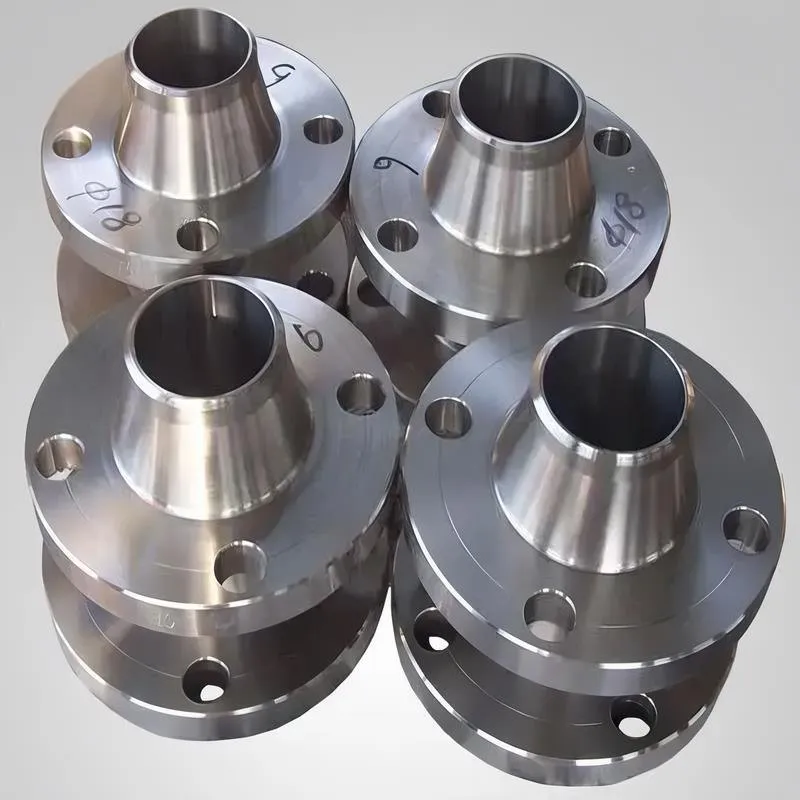
A flange—also referred to as a flange plate or rim—is a component used to connect shafts to one another, or, more commonly, to join the ends of pipes. Flanges are also utilized at the inlet and outlet ports of equipment to facilitate connections between two devices—for instance, the flange on a speed reducer. A "flange connection" or "flanged joint" refers to a detachable joint assembly comprising three interconnected elements—a flange, a gasket, and bolts—that together form a sealed structural unit. In the context of piping systems, a "pipe flange" specifically denotes a flange used for plumbing within the installation; when applied to equipment, it refers to the inlet or outlet flange of that specific device. Flanges feature a series of holes through which bolts are inserted to securely fasten the two flanges together, while a gasket placed between the flanges ensures a leak-proof seal. Flanges are broadly categorized into three types: threaded (screw-in) flanges, welded flanges, and clamp-type flanges. Flanges are invariably used in pairs; threaded flanges are suitable for low-pressure piping applications, whereas welded flanges are required for systems operating at pressures exceeding 4 kilograms per square centimeter. A sealing gasket is inserted between the two flange plates, which are then firmly secured using bolts. The thickness of a flange—as well as the specifications of the bolts used to fasten it—vary depending on the specific pressure rating required for the application. When connecting equipment such as water pumps or valves to piping systems, the corresponding connection points on these devices are often manufactured in the shape of a matching flange; this method of attachment is also referred to as a "flange connection." Generally, any connecting component that utilizes bolts to join and seal the perimeters of two flat surfaces—such as the joints in ventilation ducts—is termed a "flange"; such components may collectively be classified as "flange-type parts." However, since such a connection often constitutes merely a *portion* of a larger device—for instance, the interface between a flange and a water pump—it would be inappropriate to classify the entire water pump itself as a "flange-type part." Conversely, smaller components—such as valves—that feature such flanged interfaces may indeed be appropriately categorized as "flange-type parts."
-:-
For detailed product information, please contact sales.
-:
AISI 1055 Steel Flange, cold drawn, annealed, 19-32 mm (0.75-1.25 in) round Product Information
-:-
For detailed product information, please contact sales.
-:
AISI 1055 Steel Flange, cold drawn, annealed, 19-32 mm (0.75-1.25 in) round Synonyms
-:-
For detailed product information, please contact sales.
-:
AISI 1055 Steel, cold drawn, annealed, 19-32 mm (0.75-1.25 in) round Product Information
-:-
For detailed product information, please contact sales.
-:
# **Technical Datasheet: AISI 1055 Steel - Cold Drawn & Annealed Round Bar (19-32 mm / 0.75-1.25 in)**
---
## **1. Product Overview**
AISI 1055 cold drawn and annealed round bar is a high-carbon steel product that combines the dimensional precision of cold drawing with the optimized machinability and stress relief achieved through full annealing. This dual-process treatment produces material with exceptional dimensional accuracy, superior surface finish, and a fully softened microstructure ideal for precision machining operations. The annealing process specifically at 790-815°C (1450-1500°F) transforms the cold worked structure into a coarse pearlite-ferrite matrix, providing the softest practical condition for this steel grade while maintaining its full hardenability potential for subsequent heat treatment.
---
## **2. Key Characteristics & Advantages**
- **Optimal Machinability**: Annealed condition provides superior chip formation and extended tool life
- **Precision Dimensions**: Cold drawing ensures tight diameter tolerances (±0.05 mm / ±0.002 in typical)
- **Complete Stress Relief**: Eliminates residual stresses from cold working, minimizing distortion during machining
- **Uniform Microstructure**: Coarse pearlite structure for consistent performance
- **Enhanced Formability**: Maximum ductility for this carbon content
- **Excellent Surface Finish**: Smooth, bright surface (0.8-1.6 µm Ra) with scale-free condition
- **Predictable Hardening Response**: Ideal starting condition for subsequent quenching operations
---
## **3. Chemical Composition**
| Element | Composition Range (%) | Standard Reference |
|---------|----------------------|-------------------|
| **Carbon (C)** | 0.50 - 0.60 | ASTM A108 / SAE J403 |
| **Manganese (Mn)** | 0.60 - 0.90 | ASTM A108 / SAE J403 |
| **Phosphorus (P)** | ≤ 0.040 | ASTM A108 / SAE J403 |
| **Sulfur (S)** | ≤ 0.050 | ASTM A108 / SAE J403 |
| **Silicon (Si)** | 0.15 - 0.35 | ASTM A108 / SAE J403 |
| **Iron (Fe)** | Balance | - |
*Note: The carbon range (0.50-0.60%) places this at the higher end of medium-carbon steels, providing excellent hardenability potential.*
---
## **4. Manufacturing Process Sequence**
1. **Hot Rolling**: Initial reduction to approximate dimensions
2. **Cold Drawing**: Precision sizing (typically 10-20% area reduction)
3. **Full Annealing**: Heat to 790-815°C (1450-1500°F), slow furnace cooling at ≤25°C/hr to 500°C
4. **Stress Equalization**: Optional 600-650°C (1110-1200°F) treatment for critical applications
5. **Final Inspection**: Complete dimensional, surface, and metallurgical verification
---
## **5. Typical Mechanical Properties (Annealed Condition)**
| Property | Value Range | Test Standard |
|----------|-------------|---------------|
| **Tensile Strength** | 590 - 740 MPa (86 - 107 ksi) | ASTM A370 |
| **Yield Strength (0.2% offset)** | 330 - 480 MPa (48 - 70 ksi) | ASTM A370 |
| **Elongation in 50 mm (2")** | 18% - 25% | ASTM A370 |
| **Reduction of Area** | 50% - 65% | ASTM A370 |
| **Brinell Hardness** | 163 - 207 HB | ASTM E10 |
| **Surface Roughness (Ra)** | 0.8 - 1.6 µm (32 - 63 µin) | ASME B46.1 |
| **Modulus of Elasticity** | 200 GPa (29,000 ksi) | ASTM E111 |
| **Charpy Impact (20°C)** | 35 - 55 J (26 - 41 ft-lb) | ASTM A370 |
| **Machinability Rating** | ~55% (relative to 1212 steel) | - |
| **Residual Stress** | < 40 MPa surface compression | X-ray diffraction |
---
## **6. Microstructural Characteristics**
- **Primary Structure**: Coarse lamellar pearlite (75-85%) with grain boundary ferrite
- **Grain Size**: ASTM 5-7 (medium-coarse)
- **Pearlite Spacing**: 0.3-0.5 µm interlamellar distance
- **Phase Distribution**: Uniform throughout cross-section
- **Decarburization**: ≤ 0.15 mm (0.006 in) maximum
- **Inclusion Rating**: ASTM E45 ≤ 1.5 thin series
---
## **7. Physical & Thermal Properties**
| Property | Value |
|----------|-------|
| **Density** | 7.87 g/cm³ (0.284 lb/in³) |
| **Thermal Conductivity (20°C)** | 47.8 W/m·K (33.1 BTU·in/hr·ft²·°F) |
| **Specific Heat Capacity** | 486 J/kg·K (0.116 BTU/lb·°F) |
| **Coefficient of Thermal Expansion** | 11.3 µm/m·°C (6.3 µin/in·°F) 20-100°C |
| **Electrical Resistivity** | 0.250 µΩ·m |
| **Magnetic Properties** | Ferromagnetic |
---
## **8. International Standard Equivalents**
| Standard System | Designation | Primary Specification |
|----------------|-------------|----------------------|
| **UNS** | G10550 | Unified Numbering System |
| **SAE/AISI** | 1055 | SAE J403 |
| **ASTM** | Grade 1055 | ASTM A108 (with annealing) |
| **EN (Europe)** | 1.1208 (C56E) | EN 10083-2 |
| **ISO** | C56E | ISO 683-18 |
| **JIS (Japan)** | S55C | JIS G4051 |
| **GB (China)** | 55# (55钢) | GB/T 699 |
| **DIN (Germany)** | 1.1208, Ck56 | DIN 17200 |
---
## **9. Heat Treatment Response**
**Subsequent Hardening Capability**:
- **Austenitizing**: 830-855°C (1525-1575°F)
- **Quenching**: Water or oil for maximum hardness
- **Tempering Range**: 200-650°C (400-1200°F)
- **Maximum Hardness**: 65-67 HRC (as-quenched)
- **Typical Tempered Hardness**: 32-52 HRC depending on temperature
---
## **10. Primary Applications**
**Precision Machining Blanks**:
- Complex gear and sprocket blanks
- High-strength shaft and spindle preforms
- Tool and die component blanks
- Automotive transmission parts
- Heavy machinery components
**Industrial Components**:
- Machine tool precision parts
- Hydraulic system components
- Bearing race blanks
- Fastener stock for critical applications
- Custom engineered parts
---
## **11. Fabrication Characteristics**
**Machining Performance**:
- Excellent chip control and surface finish
- Recommended cutting speeds: 35-55 m/min
- Extended tool life compared to harder conditions
- Suitable for complex, multi-operation machining
**Forming & Welding**:
- Good cold formability with proper radii
- Welding not recommended without complete re-heat treatment
- Best practice: Complete all machining before final hardening
---
## **12. Quality Assurance**
- Full traceability and certification
- Dimensional tolerances per ASTM A108
- Microstructural verification
- Hardness testing multiple locations
- Surface finish certification
---
## **13. Comparative Advantages**
| Property | Cold Drawn Only | Cold Drawn & Annealed | Improvement |
|----------|-----------------|----------------------|-------------|
| **Machinability** | 30% | 55% | +83% |
| **Tool Life** | Standard | Extended (2-3×) | Significant |
| **Surface Finish** | 1.6-3.2 µm | 0.8-1.6 µm | 50% better |
| **Distortion Risk** | High | Low | Improved stability |
| **Total Machining Cost** | 100% | 70-85% | 15-30% savings |
---
## **14. Technical Specifications Summary**
**Dimensional Tolerances**:
- Diameter (19-32 mm): ±0.05 mm (±0.002 in)
- Straightness: ≤0.2 mm per 300 mm
- Roundness: ≤0.03 mm
**Available Conditions**:
- Standard annealed at 790-815°C
- Stress relieved (optional)
- Cut to length or standard mill lengths
**Packaging**:
- VCI paper protected
- Plastic end caps
- Bundled for secure handling
---
**Disclaimer**: This material is supplied in annealed condition for machining purposes and requires final heat treatment for service applications. Properties may vary based on specific processing parameters. Consult technical data for critical applications.
---
**Revision**: 1.0
**Date**: November 2023
**Status**: Current Specification
-:-
For detailed product information, please contact sales.
-:
AISI 1055 Steel, cold drawn, annealed, 19-32 mm (0.75-1.25 in) round Specification
Dimensions
Size:
Diameter 20-1000 mm Length <4828 mm
Size:We can customized as required
Standard:
Per your request or drawing
We can customized as required
Properties(Theoretical)
Chemical Composition
-:-
For detailed product information, please contact sales.
-:
AISI 1055 Steel, cold drawn, annealed, 19-32 mm (0.75-1.25 in) round Properties
-:-
For detailed product information, please contact sales.
-:
Applications of AISI 1055 Steel Flange, cold drawn, annealed, 19-32 mm (0.75-1.25 in) round
-:-
For detailed product information, please contact sales.
-:
Chemical Identifiers AISI 1055 Steel Flange, cold drawn, annealed, 19-32 mm (0.75-1.25 in) round
-:-
For detailed product information, please contact sales.
-:
Packing of AISI 1055 Steel Flange, cold drawn, annealed, 19-32 mm (0.75-1.25 in) round
-:-
For detailed product information, please contact sales.
-:
Standard Packing:
-:-
For detailed product information, please contact sales.
-:
Typical bulk packaging includes palletized plastic 5 gallon/25 kg. pails, fiber and Steel Flange drums to 1 ton super sacks in full container (FCL) or truck load (T/L) quantities. Research and sample quantities and hygroscopic, oxidizing or other air sensitive materials may be packaged under argon or vacuum. Solutions are packaged in polypropylene, plastic or glass jars up to palletized 1299 gallon liquid totes Special package is available on request. E FORUs’ is carefully handled to minimize damage during storage and transportation and to preserve the quality of our products in their original condition