1,We Manufacturing processes are primarily classified into four types:
1:Forging,
2:Casting,
3:Cutting,
4:Rolling.
2,We can manufacture in accordance with these standards.
Standards:
GB Series (Chinese Standards), JB Series (Machinery Standards), HG Series (Chemical Industry Standards), ASME B16.5 (American Standards), BS4504 (British Standards), DIN (German Standards), and JIS (Japanese Standards).
Internationally, there are two primary systems of pipe flange standards: the European system, represented by the German DIN standards (including those of the former Soviet Union), and the American system, represented by the US ANSI pipe flange standards. Other common standards include: the Chinese Ministry of Machinery Industry standards (JB series), the Ministry of Chemical Industry standards (HG series), the Chinese National Standard *GB/T 9112–9124-2010 Steel Pipe Flanges*, as well as US standards (ASME B16.5), British standards (BS4504), German standards (DIN), Japanese standards (JIS), and marine standards (CBM), among others.
The nominal pressure ratings for the PN series are designated by "PN" and comprise the following nine levels: PN2.5, PN6, PN10, PN16, PN25, PN40, PN63, PN100, and PN160.
The nominal pressure ratings for the Class series are designated by "Class" and comprise the following six levels: Class150, Class300, Class600, Class900, Class1500, and Class2500.
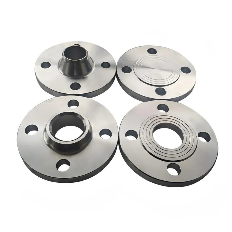
Flange Classification
1. **According to Chemical Industry Standards:** Flanges are classified as follows:
Plate Flat Welding Flange (PL), Necked Flat Welding Flange (SO), Necked Butt Welding Flange (WN), Integral Flange (IF), Socket Welding Flange (SW), Threaded Flange (Th), Butt Welding Ring Loose Flange (PJ/SE), Blind Flange (BL), Flat Welding Ring Loose Flange (PJ/PJ), and Lined Blind Flange (BL(s)).
2. **According to Petrochemical (SH) Industry Standards:** Flanges are classified as follows:
Threaded Flange (PL), Butt Welding Flange (WN), Flat Welding Flange (SO), Socket Welding Flange (SW), Loose Flange (LJ), and Blind Flange (no specific designation).
3. **According to Machinery (JB) Industry Standards:** Flanges are classified as follows:
Integral Flange, Butt Welding Flange, Plate Flat Welding Flange, Butt Welding Ring Plate Loose Flange, Flat Welding Ring Plate Loose Flange, Lap Joint Ring Plate Loose Flange, and Blind Flange.
4. **According to Connection Method/Type:** Flanges are classified as follows:
Plate Flat Welding Flange, Necked Flat Welding Flange, Necked Butt Welding Flange, Socket Welding Flange, Threaded Flange, Blind Flange, Necked Butt Welding Ring Loose Flange, Flat Welding Ring Loose Flange, Ring-Type Joint (RTJ) Flange and Blind Flange, Large-Diameter Plate Flange, Large-Diameter High-Neck Flange, Figure-8 Blind Plate, Butt Welding Ring Loose Flange, etc.
5. **According to the Component Being Connected:** Flanges can be classified into Vessel Flanges and Pipe Flanges.
6. **According to Structural Type:** Flanges include Integral Flanges, Threaded Flanges, Flat Welding Flanges, Butt Welding Flanges, Lap Joint (Loose/Swivel) Flanges, and Blind Flanges.
A flange—also referred to as a flange plate or rim—is a component used to connect shafts to one another, or, more commonly, to join the ends of pipes. Flanges are also utilized at the inlet and outlet ports of equipment to facilitate connections between two devices—for instance, the flange on a speed reducer. A "flange connection" or "flanged joint" refers to a detachable joint assembly comprising three interconnected elements—a flange, a gasket, and bolts—that together form a sealed structural unit. In the context of piping systems, a "pipe flange" specifically denotes a flange used for plumbing within the installation; when applied to equipment, it refers to the inlet or outlet flange of that specific device. Flanges feature a series of holes through which bolts are inserted to securely fasten the two flanges together, while a gasket placed between the flanges ensures a leak-proof seal. Flanges are broadly categorized into three types: threaded (screw-in) flanges, welded flanges, and clamp-type flanges. Flanges are invariably used in pairs; threaded flanges are suitable for low-pressure piping applications, whereas welded flanges are required for systems operating at pressures exceeding 4 kilograms per square centimeter. A sealing gasket is inserted between the two flange plates, which are then firmly secured using bolts. The thickness of a flange—as well as the specifications of the bolts used to fasten it—vary depending on the specific pressure rating required for the application. When connecting equipment such as water pumps or valves to piping systems, the corresponding connection points on these devices are often manufactured in the shape of a matching flange; this method of attachment is also referred to as a "flange connection." Generally, any connecting component that utilizes bolts to join and seal the perimeters of two flat surfaces—such as the joints in ventilation ducts—is termed a "flange"; such components may collectively be classified as "flange-type parts." However, since such a connection often constitutes merely a *portion* of a larger device—for instance, the interface between a flange and a water pump—it would be inappropriate to classify the entire water pump itself as a "flange-type part." Conversely, smaller components—such as valves—that feature such flanged interfaces may indeed be appropriately categorized as "flange-type parts."
-:-
For detailed product information, please contact sales.
-:
EN 1.0143 Structural, Hot Rolled, Quality Steel Flange, t 200-250 mm Product Information
-:-
For detailed product information, please contact sales.
-:
EN 1.0143 Structural, Hot Rolled, Quality Steel Flange, t 200-250 mm Synonyms
-:-
For detailed product information, please contact sales.
-:
EN 1.0143 Structural, Hot Rolled, Quality Steel, t 200-250 mm Product Information
-:-
For detailed product information, please contact sales.
-:
# **Technical Datasheet: EN 1.0143 (S275J0) Structural Steel**
**Thickness Range: 200-250 mm | Condition: Hot Rolled, Normalized (N)**
## **1. PRODUCT OVERVIEW**
**EN 1.0143 (S275J0)** in the **extra-heavy thickness range of 200-250 mm** represents a **specialized, high-quality structural steel** specifically engineered for **massive structural components** requiring **certified impact toughness at 0°C**. This ultra-thick plate variant undergoes **specialized manufacturing processes** including controlled rolling, extended normalizing, and enhanced quality controls to ensure **through-thickness property uniformity** and **resistance to centerline segregation** – critical challenges in such substantial cross-sections.
Supplied exclusively in the **normalized or thermomechanically rolled condition**, this material is designed for **heavy civil engineering, offshore structures, and power generation applications** where extreme thicknesses combine with moderate low-temperature service requirements. The "J0" designation (0°C impact testing) provides assurance against brittle fracture in service temperatures down to approximately -10°C, a critical consideration for thick sections where triaxial stress states increase fracture risk.
**Key Characteristics for 200-250 mm Thickness:**
- **Through-Thickness Property Control:** Specialized processing minimizes centerline segregation
- **Guaranteed Moderate Temperature Toughness:** Minimum 27J impact energy at 0°C, tested at quarter-thickness
- **Heavy Fabrication Optimized:** Chemistry and processing tailored for welding and machining of massive sections
- **Strict Quality Assurance:** Enhanced non-destructive testing and multiple mechanical tests
- **Structural Reliability:** Verified performance for safety-critical applications in moderate climates with thick sections
---
## **2. CHEMICAL COMPOSITION (200-250 mm)**
**Compliance:** EN 10025-2:2019 - With special controls for heavy sections
*Enhanced chemistry control to address centerline segregation in ultra-thick plates*
| Element | Maximum (%) | Typical Range (%) | Metallurgical Significance for 200-250 mm |
|---------|------------|------------------|-------------------------------------------|
| **Carbon (C)** | **0.18** | 0.12-0.16 | Deliberately controlled at lower range to maintain weldability and toughness in slow-cooled sections |
| **Manganese (Mn)** | **1.50** | 1.25-1.45 | **Critical for through-thickness properties**; higher end of range to compensate for segregation effects |
| **Phosphorus (P)** | **0.020** | ≤0.015 | Extremely tight control to prevent centerline embrittlement |
| **Sulfur (S)** | **0.015** | ≤0.008 | Ultra-low with calcium treatment for sulfide shape control (Type II inclusions) |
| **Silicon (Si)** | **0.50** | 0.20-0.35 | Reduced maximum compared to thinner sections for improved toughness |
| **Aluminum, total (Alt)** | — | **0.030-0.070** | Enhanced grain refinement through entire thickness |
| **Nitrogen (N)** | **0.010** | ≤0.007 | Tighter control to minimize aging in slow-cooled sections |
| **Calcium (Ca)** | 0.005 | 0.001-0.003 | **Mandatory for sulfide shape control** in heavy sections |
| **Microalloying Elements** | As agreed | Nb: 0.010-0.030
V: 0.005-0.015 | For grain refinement in controlled rolling |
| **Residual Elements** | Stricter limits | Cu ≤0.25, Cr ≤0.15, Ni ≤0.15, Mo ≤0.05 | Enhanced control for weldability |
| **Iron (Fe)** | Balance | Balance | Base metal |
**Special Chemical Considerations for 200-250 mm:**
- **Carbon Equivalent (CEV):** 0.35-0.40% (CEIIW = C + Mn/6) - Controlled at lower end
- **Cracking Parameter (Pcm):** 0.19-0.23% - Optimized for heavy-section welding
- **Segregation Control:** Intentional chemistry adjustments to minimize Mn and P banding
- **Cleanness Requirements:** Enhanced inclusion control per SEP 1571 or equivalent
- **Optional Enhanced Melting:** ESR (Electroslag Remelting) or VD (Vacuum Degassing) available
---
## **3. PHYSICAL & MECHANICAL PROPERTIES**
### **A. Physical Properties (Typical at 20°C):**
- **Density:** 7.85 g/cm³
- **Modulus of Elasticity (E):** 210 GPa (may show slight anisotropy)
- **Shear Modulus (G):** 81 GPa
- **Poisson's Ratio (ν):** 0.30
- **Coefficient of Thermal Expansion:** 11.8 × 10⁻⁶/K (20-100°C)
- **Thermal Conductivity:** 47 W/(m·K) at 20°C (reduced due to microstructure)
- **Specific Heat Capacity:** 460 J/(kg·K)
- **Electrical Resistivity:** 0.17 μΩ·m
- **Acoustic Properties:** Longitudinal velocity 5850 m/s, Shear velocity 3200 m/s
### **B. Mandatory Mechanical Properties (EN 10025-2 for t > 150 mm):**
*Note: EN 10025-2 does not specify values beyond 150 mm; these are based on manufacturer guarantees and project specifications*
| Property | Symbol | Guaranteed Minimum | Test Position | Test Standard |
|----------|--------|-------------------|---------------|---------------|
| **Yield Strength** | ReH | **200 MPa** | Quarter-thickness | EN ISO 6892-1 |
| **Tensile Strength** | Rm | **340-490 MPa** | Quarter-thickness | EN ISO 6892-1 |
| **Minimum Elongation** | A | **18%** | Quarter-thickness | EN ISO 6892-1 |
| **Impact Energy** | KV | **27 J at 0°C** | Quarter-thickness | EN ISO 148-1 |
### **C. Through-Thickness Property Gradient (Typical for 225 mm):**
| Property | Surface (0 mm) | Quarter-Thickness (56 mm) | Half-Thickness (112 mm) | Centerline (112 mm) |
|----------|----------------|---------------------------|-------------------------|---------------------|
| **Yield Strength** | 240-280 MPa | 210-250 MPa | 200-240 MPa | 190-230 MPa |
| **Tensile Strength** | 380-440 MPa | 350-410 MPa | 340-400 MPa | 330-390 MPa |
| **Elongation** | 22-28% | 18-24% | 16-22% | 15-20% |
| **Impact Energy (0°C)** | 40-80 J | 30-60 J | 25-50 J | 20-45 J |
| **Hardness (HB)** | 130-150 | 115-135 | 110-130 | 105-125 |
| **Through-Thickness RA** | 55-65% | 35-45% | 25-35% | 20-30% |
### **D. Special Properties for Ultra-Thick Sections:**
- **Z-Direction Properties:** Through-thickness reduction in area typically 15-25% at centerline
- **Fracture Toughness:** CTOD values 0.10-0.25 mm at 0°C (centerline)
- **Fatigue Strength:** 120-150 MPa at 2×10⁶ cycles (as-rolled surface)
- **Brittle Fracture Resistance:** Enhanced by fine grain structure despite thickness
- **Residual Stress Profile:** Characteristic "M-shaped" distribution through thickness
---
## **4. MANUFACTURING & PROCESSING (200-250 mm)**
### **A. Special Manufacturing Requirements:**
- **Steelmaking:** Electric arc furnace or basic oxygen furnace with ladle refining
- **Casting:** Continuous casting with soft reduction or ingot casting with controlled solidification
- **Rolling:** Controlled rolling with multiple passes and controlled cooling
- **Heat Treatment:** **Normalizing mandatory** - 900-930°C with extended soak times (typically 2.5-3.5 hours)
- **Testing:** Extensive mechanical testing at multiple through-thickness locations
### **B. Cutting & Machining:**
- **Thermal Cutting:** Oxy-fuel with 150-200°C preheat; plasma for precision edges
- **Mechanical Cutting:** Band saws with special blades; very slow feed rates
- **Machining Parameters:**
- Turning: 60-100 m/min, feed 0.3-0.5 mm/rev
- Milling: 40-80 m/min, feed 0.2-0.4 mm/tooth
- Drilling: 15-30 m/min, **mandatory peck drilling**
- **Edge Preparation:** Machining required for highly stressed edges to remove thermal effects
### **C. Welding Procedures (Critical for 200-250 mm):**
**Mandatory Requirements:**
- **Preheating:** 150-200°C minimum, based on actual CEV and restraint
- **Interpass Temperature:** 150-250°C maximum
- **Post-Weld Heat Treatment:** **Mandatory** - 580-620°C for extended periods (typically 4-8 hours)
- **Heat Input Control:** 2.0-4.0 kJ/mm depending on process
**Recommended Welding Processes:**
| Process | Application | Preheat | PWHT | Special Considerations |
|---------|-------------|---------|------|------------------------|
| **SMAW** | Root passes, repairs | 175°C | Mandatory | Low-hydrogen electrodes essential |
| **SAW** | Main seams | 200°C | Mandatory | Multiple wire techniques common |
| **FCAW** | Out-of-position | 175°C | Mandatory | Gas-shielded preferred |
| **Electroslag** | Very thick welds | Not required | Mandatory+Normalizing | For maximum productivity |
**Weld Procedure Qualification:** **Extensive qualification required** including:
- Through-thickness tensile tests at multiple locations
- Charpy testing at surface, quarter, and centerline positions
- CTOD testing for fracture-critical applications
- Macroscopic examination for fusion and HAZ characteristics
---
## **5. TYPICAL APPLICATIONS**
### **A. Heavy Civil Engineering:**
- **Hydroelectric Projects:** Dam gate components, turbine casings, spiral cases
- **Bridge Construction:** Massive pier caps, anchor blocks, bearing supports for long-span bridges
- **Lock & Canal Systems:** Massive gate leaves, operating machinery foundations
- **Tunnel Engineering:** Tunnel boring machine components, segment molds
### **B. Offshore & Marine Structures:**
- **Fixed Offshore Platforms:** Leg nodes, pile sleeves, conductor guides
- **Shipbuilding:** Keel blocks, stern frames, rudder stocks for large vessels
- **Dry Dock Components:** Caisson gates, dock gate hinges
- **Heavy Marine Equipment:** Crane pedestals, winch foundations
### **C. Power Generation:**
- **Thermal Power:** Turbine foundations, generator pedestals, boiler supports
- **Nuclear Facilities:** Secondary containment structures (non-nuclear grade), equipment supports
- **Hydroelectric:** Turbine stay rings, generator frames, governor bases
- **Heavy Foundations:** For turbines, generators, and other rotating equipment
### **D. Heavy Industrial Applications:**
- **Press Frames:** Forging press components, extrusion press frames
- **Mill Equipment:** Rolling mill housings, back-up roll chocks, shear frames
- **Mining:** Crusher frames, shovel components, hoist foundations
- **Heavy Machinery:** Test machine frames, calibration equipment bases
### **E. Specialized Applications:**
- **Research Facilities:** Particle accelerator components, test reactor structures
- **Defense:** Heavy vehicle components, protective structures
- **Transportation:** Railway turntables, heavy lift device components
- **Special Foundations:** For telescopes, large antennas, scientific instruments
**Application Limitations:**
- **Not for pressure containment** unless specifically qualified
- **Limited to moderate temperatures** (design temperature ≥ -10°C)
- **Not for highly corrosive environments** without protection
- **Requires specialized fabrication facilities** and expertise
---
## **6. INTERNATIONAL STANDARDS & EQUIVALENTS**
### **Primary Designations:**
- **EN Standard:** EN 10025-2:2019 (with special agreement for t > 150 mm)
- **Material Number:** 1.0143
- **Steel Name:** S275J0+N (Normalized mandatory)
- **Supplementary Standards:** EN 10164 (Z-quality), EN 10204 (certification)
### **Global Equivalents for Ultra-Thick Sections:**
| Country/Standard | Equivalent Concept | Thickness Range | Key Comparison Notes |
|-----------------|-------------------|-----------------|----------------------|
| **ISO** | Agreement between parties | Up to 250 mm | Properties by negotiation |
| **USA (ASTM)** | ASTM A6 Plate | Up to 305 mm (12") | Similar but different testing requirements |
| **USA (ASTM)** | ASTM A283 Gr. D with Z-quality | Up to 200 mm | Similar moderate strength |
| **Japan (JIS)** | JIS G3106 SM490A with special quality | Up to 200 mm | Different testing philosophy |
| **Germany (DIN)** | DIN EN 10025-2 S275J0 with Sondervereinbarung | Up to 250 mm | Direct adoption with special agreement |
| **China (GB)** | GB/T 1591 Q275D with Z-direction requirements | Up to 200 mm | Similar enhanced quality concept |
| **Korea (KS)** | KS D 3503 with special quality | Up to 200 mm | Different classification system |
### **Thickness-Dependent Property Derating (Typical):**
| Thickness (mm) | Yield Strength Factor | Impact Test Location | Special Requirements |
|----------------|-----------------------|----------------------|----------------------|
| **≤ 40** | 1.00 (275 MPa) | Surface | Standard testing |
| **40-100** | 0.91 (250 MPa) | 1/4 thickness | Normalizing recommended |
| **100-150** | 0.82 (225 MPa) | 1/4 thickness | Normalizing mandatory |
| **150-200** | 0.73 (200 MPa) | 1/4 thickness | Enhanced testing |
| **200-250** | **0.67 (185 MPa)** | **Multiple locations** | **Special manufacturing agreement** |
---
## **7. QUALITY ASSURANCE & TESTING**
### **Mandatory Testing for 200-250 mm Plate:**
1. **Tensile Tests:** Minimum three tests (surface, quarter, centerline)
2. **Impact Tests:** Three sets at 0°C (surface, quarter, centerline)
3. **Bend Tests:** Transverse at surface and quarter thickness
4. **Ultrasonic Testing:** 100% per EN 10160 Class S3E4 minimum
5. **Macroexamination:** Full thickness etched section for segregation assessment
### **Enhanced Testing for Critical Applications:**
- **Drop-Weight Tear Test (DWTT):** For fracture arrest assessment
- **CTOD Testing:** At multiple through-thickness locations
- **Residual Stress Measurement:** Using hole-drilling or X-ray diffraction
- **Sulfur Print:** For segregation pattern evaluation
- **Inclusion Rating:** Multiple locations per SEP 1571 or ASTM E45
### **Certification Requirements:**
- **EN 10204 3.2 Certificate:** **Mandatory** with independent inspection
- **Heat Treatment Records:** Complete normalizing cycle with temperature charts
- **NDT Reports:** Ultrasonic testing with indication mapping
- **Traceability:** Unique identification of each plate with test location maps
- **Material Test Reports:** Comprehensive including all supplementary tests
---
## **8. DESIGN & SPECIFICATION CONSIDERATIONS**
### **Design Advantages:**
1. **Availability in Extreme Thicknesses:** One of few structural grades available up to 250 mm
2. **Moderate Temperature Capability:** Suitable for applications down to -10°C
3. **Proven Performance:** Extensive use in heavy civil engineering
4. **Economic Alternative:** More cost-effective than alloy steels for many applications
5. **Code Acceptance:** Recognized in major structural design codes with appropriate derating
### **Critical Design Limitations:**
1. **Significant Strength Reduction:** Approximately 33% lower yield strength than 16 mm material
2. **Anisotropic Properties:** Substantial through-thickness property variations
3. **Welding Challenges:** Complex procedures with high preheat and mandatory PWHT
4. **Fabrication Restrictions:** Limited to specialized fabricators with appropriate equipment
5. **Lead Time:** Typically 12-20 weeks for manufacture and testing
### **Specification Best Practices:**
```plaintext
EN 10025-2 S275J0+N with Special Agreement for 225 mm thickness
Supplementary Requirements:
- Minimum yield strength: 200 MPa at quarter-thickness
- Impact testing at 0°C: 27J min at surface, quarter, and centerline
- Ultrasonic testing: EN 10160 Class S3E4 with report
- Through-thickness tensile testing: Z15 minimum
- Normalizing: Full cycle documentation required
- Certification: EN 10204 3.2 with independent inspection
- Marking: Heat number, test locations, orientation marks
```
### **Fabrication Sequence Recommendations:**
1. **Material Certification Review:** Complete before fabrication begins
2. **Welding Procedure Qualification:** Extensive qualification required
3. **Preheat Verification:** Continuous monitoring during welding
4. **NDT Planning:** Phased examination during fabrication
5. **PWHT Coordination:** Furnace availability and temperature uniformity verification
6. **Final Inspection:** Comprehensive before shipment
---
## **9. TRANSPORTATION & HANDLING**
### **Special Handling Requirements:**
- **Lifting:** Multiple lift points with spreader beams to prevent plate distortion
- **Storage:** Horizontal on multiple continuous supports to prevent sagging
- **Temperature Control:** Protect from rapid temperature changes
- **Identification:** Permanent marking including test locations and orientation
### **Transportation Considerations:**
- **Weight Limitations:** Single plates may exceed 4,000 kg per square meter
- **Equipment Requirements:** Specialized trailers and handling equipment
- **Route Planning:** Consider bridge weight limits and access restrictions
- **Packaging:** Protective coating to prevent corrosion during transit
---
## **10. TECHNICAL SUMMARY**
**EN 1.0143 (S275J0)** in the **200-250 mm thickness range** represents a **highly specialized structural steel solution** for applications requiring **extreme thickness combined with moderate low-temperature toughness**. While maintaining the fundamental S275 strength classification, this ultra-thick variant requires **sophisticated manufacturing controls, specialized heat treatment, and complex fabrication procedures** to ensure reliable performance.
**Market Position:** S275J0 in 200-250 mm thickness occupies a niche market segment, primarily serving:
- Heavy civil engineering projects
- Power generation equipment foundations
- Specialized industrial machinery
- Offshore and marine heavy components
**Industry Trends:** Increasing demand for renewable energy infrastructure (particularly hydroelectric and offshore wind) is driving need for ultra-thick structural plates. However, the market is also seeing competition from alternative solutions including fabricated assemblies from thinner plates and concrete composites.
**Selection Decision Framework:**
- **Choose 200-250 mm S275J0 when:** Monolithic construction is preferred, extreme thickness is functionally required, and moderate strength is sufficient
- **Consider fabricated alternatives when:** Higher strength is needed, welding of extreme thickness poses challenges, or transportation/logistics favor smaller components
- **Evaluate higher grades when:** Strength requirements exceed S275J0 capacity even with thickness, or service temperatures are lower than -10°C
**Final Recommendation:** **S275J0 in 200-250 mm thickness should be specified only when justified by specific engineering requirements** that cannot be met by alternative construction methods. Its use requires **specialized manufacturing, rigorous quality control, and expert fabrication** – all of which contribute to significant cost and lead time implications that must be balanced against project requirements.
---
**Critical Notice for Ultra-Thick Applications:** This technical information is based on **manufacturer capabilities and special agreements** beyond standard EN 10025-2 requirements. For projects considering 200-250 mm thickness:
1. **Early Engagement:** Consult with steel manufacturers and fabricators during design phase
2. **Performance Verification:** Conduct project-specific testing to confirm properties
3. **Fabrication Assessment:** Verify fabricator capability and experience
4. **Cost-Benefit Analysis:** Compare against alternative construction methods
5. **Risk Management:** Consider all implications of working with extreme thicknesses
**Properties are not guaranteed by EN 10025-2 for thicknesses > 150 mm** and must be specifically agreed between purchaser and manufacturer. Always obtain written quotations with guaranteed properties and testing requirements before specification.
-:-
For detailed product information, please contact sales.
-:
EN 1.0143 Structural, Hot Rolled, Quality Steel, t 200-250 mm Specification
Dimensions
Size:
Diameter 20-1000 mm Length <5794 mm
Size:We can customized as required
Standard:
Per your request or drawing
We can customized as required
Properties(Theoretical)
Chemical Composition
-:-
For detailed product information, please contact sales.
-:
EN 1.0143 Structural, Hot Rolled, Quality Steel, t 200-250 mm Properties
-:-
For detailed product information, please contact sales.
-:
Applications of EN 1.0143 Structural, Hot Rolled, Quality Steel Flange, t 200-250 mm
-:-
For detailed product information, please contact sales.
-:
Chemical Identifiers EN 1.0143 Structural, Hot Rolled, Quality Steel Flange, t 200-250 mm
-:-
For detailed product information, please contact sales.
-:
Packing of EN 1.0143 Structural, Hot Rolled, Quality Steel Flange, t 200-250 mm
-:-
For detailed product information, please contact sales.
-:
Standard Packing:
-:-
For detailed product information, please contact sales.
-:
Typical bulk packaging includes palletized plastic 5 gallon/25 kg. pails, fiber and Steel Flange drums to 1 ton super sacks in full container (FCL) or truck load (T/L) quantities. Research and sample quantities and hygroscopic, oxidizing or other air sensitive materials may be packaged under argon or vacuum. Solutions are packaged in polypropylene, plastic or glass jars up to palletized 2265 gallon liquid totes Special package is available on request. E FORUs’ is carefully handled to minimize damage during storage and transportation and to preserve the quality of our products in their original condition