1,We Manufacturing processes are primarily classified into four types:
1:Forging,
2:Casting,
3:Cutting,
4:Rolling.
2,We can manufacture in accordance with these standards.
Standards:
GB Series (Chinese Standards), JB Series (Machinery Standards), HG Series (Chemical Industry Standards), ASME B16.5 (American Standards), BS4504 (British Standards), DIN (German Standards), and JIS (Japanese Standards).
Internationally, there are two primary systems of pipe flange standards: the European system, represented by the German DIN standards (including those of the former Soviet Union), and the American system, represented by the US ANSI pipe flange standards. Other common standards include: the Chinese Ministry of Machinery Industry standards (JB series), the Ministry of Chemical Industry standards (HG series), the Chinese National Standard *GB/T 9112–9124-2010 Steel Pipe Flanges*, as well as US standards (ASME B16.5), British standards (BS4504), German standards (DIN), Japanese standards (JIS), and marine standards (CBM), among others.
The nominal pressure ratings for the PN series are designated by "PN" and comprise the following nine levels: PN2.5, PN6, PN10, PN16, PN25, PN40, PN63, PN100, and PN160.
The nominal pressure ratings for the Class series are designated by "Class" and comprise the following six levels: Class150, Class300, Class600, Class900, Class1500, and Class2500.
Flange Classification
1. **According to Chemical Industry Standards:** Flanges are classified as follows:
Plate Flat Welding Flange (PL), Necked Flat Welding Flange (SO), Necked Butt Welding Flange (WN), Integral Flange (IF), Socket Welding Flange (SW), Threaded Flange (Th), Butt Welding Ring Loose Flange (PJ/SE), Blind Flange (BL), Flat Welding Ring Loose Flange (PJ/PJ), and Lined Blind Flange (BL(s)).
2. **According to Petrochemical (SH) Industry Standards:** Flanges are classified as follows:
Threaded Flange (PL), Butt Welding Flange (WN), Flat Welding Flange (SO), Socket Welding Flange (SW), Loose Flange (LJ), and Blind Flange (no specific designation).
3. **According to Machinery (JB) Industry Standards:** Flanges are classified as follows:
Integral Flange, Butt Welding Flange, Plate Flat Welding Flange, Butt Welding Ring Plate Loose Flange, Flat Welding Ring Plate Loose Flange, Lap Joint Ring Plate Loose Flange, and Blind Flange.
4. **According to Connection Method/Type:** Flanges are classified as follows:
Plate Flat Welding Flange, Necked Flat Welding Flange, Necked Butt Welding Flange, Socket Welding Flange, Threaded Flange, Blind Flange, Necked Butt Welding Ring Loose Flange, Flat Welding Ring Loose Flange, Ring-Type Joint (RTJ) Flange and Blind Flange, Large-Diameter Plate Flange, Large-Diameter High-Neck Flange, Figure-8 Blind Plate, Butt Welding Ring Loose Flange, etc.
5. **According to the Component Being Connected:** Flanges can be classified into Vessel Flanges and Pipe Flanges.
6. **According to Structural Type:** Flanges include Integral Flanges, Threaded Flanges, Flat Welding Flanges, Butt Welding Flanges, Lap Joint (Loose/Swivel) Flanges, and Blind Flanges.
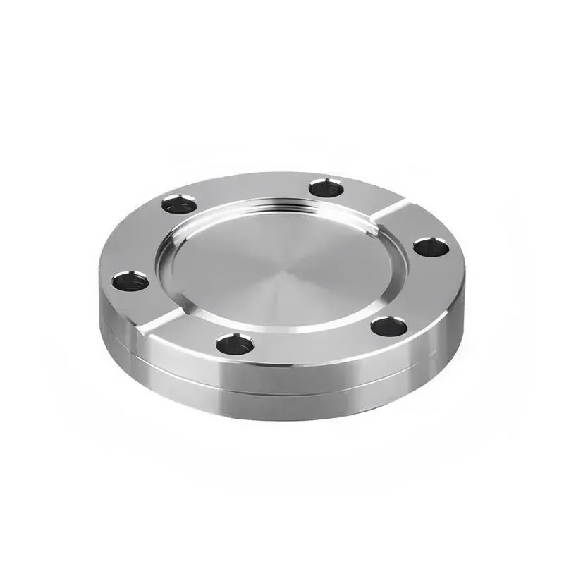
A flange—also referred to as a flange plate or rim—is a component used to connect shafts to one another, or, more commonly, to join the ends of pipes. Flanges are also utilized at the inlet and outlet ports of equipment to facilitate connections between two devices—for instance, the flange on a speed reducer. A "flange connection" or "flanged joint" refers to a detachable joint assembly comprising three interconnected elements—a flange, a gasket, and bolts—that together form a sealed structural unit. In the context of piping systems, a "pipe flange" specifically denotes a flange used for plumbing within the installation; when applied to equipment, it refers to the inlet or outlet flange of that specific device. Flanges feature a series of holes through which bolts are inserted to securely fasten the two flanges together, while a gasket placed between the flanges ensures a leak-proof seal. Flanges are broadly categorized into three types: threaded (screw-in) flanges, welded flanges, and clamp-type flanges. Flanges are invariably used in pairs; threaded flanges are suitable for low-pressure piping applications, whereas welded flanges are required for systems operating at pressures exceeding 4 kilograms per square centimeter. A sealing gasket is inserted between the two flange plates, which are then firmly secured using bolts. The thickness of a flange—as well as the specifications of the bolts used to fasten it—vary depending on the specific pressure rating required for the application. When connecting equipment such as water pumps or valves to piping systems, the corresponding connection points on these devices are often manufactured in the shape of a matching flange; this method of attachment is also referred to as a "flange connection." Generally, any connecting component that utilizes bolts to join and seal the perimeters of two flat surfaces—such as the joints in ventilation ducts—is termed a "flange"; such components may collectively be classified as "flange-type parts." However, since such a connection often constitutes merely a *portion* of a larger device—for instance, the interface between a flange and a water pump—it would be inappropriate to classify the entire water pump itself as a "flange-type part." Conversely, smaller components—such as valves—that feature such flanged interfaces may indeed be appropriately categorized as "flange-type parts."
-:-
For detailed product information, please contact sales.
-:
Latrobe LSS™ S7 Shock-Resisting Tool Steel Flange (ASTM S7) Product Information
-:-
For detailed product information, please contact sales.
-:
Latrobe LSS™ S7 Shock-Resisting Tool Steel Flange (ASTM S7) Synonyms
-:-
For detailed product information, please contact sales.
-:
Latrobe LSS™ S7 Shock-Resisting Tool Steel (ASTM S7) Product Information
-:-
For detailed product information, please contact sales.
-:
# **PRODUCT DATASHEET: LATROBE LSS™ S7 SHOCK-RESISTING TOOL STEEL (ASTM S7)**
## **EXECUTIVE SUMMARY**
Latrobe LSS™ **S7 Shock-Resisting Tool Steel** represents the **pinnacle of shock-resistance combined with exceptional air-hardening capability** in the tool steel industry. As the **premium grade within the S-series (shock-resisting) classification**, S7 delivers **unmatched toughness (up to 325 ft-lb Charpy impact) with excellent wear resistance and dimensional stability** during heat treatment. This **chromium-molybdenum alloy steel** is specifically engineered for applications subjected to **severe impact loading, high stress, and demanding service conditions** where tool failure is not an option.
Distinguished by its unique **air-hardening characteristics and deep hardenability**, Latrobe S7 maintains superior dimensional stability with minimal distortion during heat treatment—a critical advantage for precision tools and dies. Manufactured using proprietary melting and thermomechanical processing, this grade offers **enhanced microstructural homogeneity, optimized carbide distribution, and consistent mechanical properties** that exceed conventional S7 standards. With its balanced combination of **high toughness, good wear resistance, and excellent machinability in the annealed state**, S7 has become the material of choice for **punches, dies, shear blades, and other impact tools** across demanding industries.
---
## **METALLURGICAL DESIGN**
### **Material Innovation**
S7 tool steel employs a sophisticated **chromium-molybdenum-silicon alloying system** engineered to achieve:
1. **Maximum Shock Absorption:** Medium carbon content (0.45-0.55%) combined with silicon (0.20-1.00%) creates a microstructure that effectively absorbs and dissipates impact energy
2. **Air-Hardening Capability:** 3.00-3.50% chromium content enables full hardening through air cooling, minimizing thermal stresses and distortion
3. **Tempering Resistance:** Molybdenum (1.30-1.80%) provides excellent secondary hardening response and maintains hardness at elevated temperatures
4. **Deep Hardenability:** Optimized alloy balance ensures consistent through-hardening in substantial cross-sections
### **Manufacturing Excellence**
- **Advanced Melting Practices:** Electric arc furnace with ladle refining for superior cleanliness
- **Controlled Solidification:** Optimized ingot casting to minimize segregation
- **Precision Thermomechanical Processing:** Forged at carefully controlled temperatures to refine grain structure
- **Stress Management:** Gradual cooling and specialized annealing for minimal residual stresses
- **Quality Verification:** Comprehensive testing at multiple processing stages
### **Microstructural Advantages**
- **Fine Austenitic Grain Size:** ASTM 8-10 for optimal toughness
- **Uniform Carbide Distribution:** Fine, evenly dispersed carbides for balanced wear resistance
- **Tempered Martensite Matrix:** Optimized for maximum impact energy absorption
- **Minimal Retained Austenite:** Typically <5% for dimensional stability
---
## **CHEMICAL COMPOSITION**
### **Standard Composition (Weight %)**
| Element | Minimum | Maximum | Typical | Metallurgical Function |
|---------|---------|---------|---------|------------------------|
| **Carbon (C)** | 0.45 | 0.55 | 0.50 | Hardness, strength, wear resistance base |
| **Chromium (Cr)** | 3.00 | 3.50 | 3.25 | Hardenability, wear resistance, air-hardening capability |
| **Molybdenum (Mo)** | 1.30 | 1.80 | 1.55 | Secondary hardening, toughness, temper resistance |
| **Silicon (Si)** | 0.20 | 1.00 | 0.60 | Toughness enhancement, temper resistance, deoxidation |
| **Manganese (Mn)** | 0.20 | 0.60 | 0.40 | Hardenability, strength |
| **Vanadium (V)** | 0.15 | 0.30 | 0.22 | Grain refinement, secondary hardening, wear resistance |
| **Nickel (Ni)** | — | 0.25 | 0.15 | Optional, improves toughness in heavy sections |
| **Sulfur (S)** | — | 0.030 | 0.010 | Residual (controlled for machinability) |
| **Phosphorus (P)** | — | 0.030 | 0.015 | Residual (minimized for toughness) |
### **Latrobe Premium Modifications**
- **Enhanced Purity:** Extra-low sulfur and phosphorus (S<0.008%, P<0.012%) for superior transverse toughness
- **Micro-Alloying:** Controlled boron additions (0.001-0.003%) for optimized hardenability in large sections
- **Gas Control:** Oxygen <20 ppm, Hydrogen <1.5 ppm through vacuum degassing
- **Trace Element Management:** Tin, antimony, arsenic controlled to minimize temper embrittlement
### **Comparative Chemistry Advantages**
- **Optimized Chromium:** Higher than other S-grades for superior air-hardening capability
- **Balanced Molybdenum:** Provides excellent tempering response without excessive carbide formation
- **Controlled Silicon:** Enough for toughness enhancement without compromising machinability
- **Vanadium Precision:** Sufficient for grain refinement while maintaining grindability
---
## **PHYSICAL & MECHANICAL PROPERTIES**
### **Hardened and Tempered Condition**
*Typical Heat Treatment: Austenitize 1750°F (954°C), air cool, double temper*
| Property | 54-56 HRC | 56-58 HRC | 58-60 HRC | 60-62 HRC | Units |
|----------|------------|------------|------------|------------|--------|
| **Hardness** | 54-56 | 56-58 | 58-60 | 60-62 | HRC |
| **Tensile Strength** | 280-300 | 300-320 | 320-340 | 340-360 | ksi |
| **Yield Strength (0.2%)** | 250-270 | 270-290 | 290-310 | 310-330 | ksi |
| **Compressive Strength** | 350-370 | 370-390 | 390-410 | 410-430 | ksi |
| **Elongation** | 12-14 | 10-12 | 8-10 | 6-8 | % |
| **Reduction of Area** | 45-50 | 40-45 | 35-40 | 30-35 | % |
| **Impact Energy (Charpy V)** | 300-325 | 250-300 | 200-250 | 150-200 | ft-lb |
### **Physical Properties**
| Property | Value | Units | Test Standard |
|----------|-------|--------|----------------|
| **Density** | 0.284 lb/in³ | 7.86 g/cm³ | ASTM B311 |
| **Elastic Modulus** | 29.0 × 10⁶ psi | 200 GPa | ASTM E111 |
| **Shear Modulus** | 11.2 × 10⁶ psi | 77 GPa | ASTM E143 |
| **Poisson's Ratio** | 0.29 | | ASTM E132 |
| **Thermal Conductivity** | 21.0 BTU·in/(hr·ft²·°F) | 30.3 W/(m·K) @ 100°C | ASTM E1225 |
| **Specific Heat** | 0.11 BTU/(lb·°F) | 460 J/(kg·K) | ASTM E1269 |
| **Coefficient of Thermal Expansion** | 6.5 × 10⁻⁶ /°F | 11.7 × 10⁻⁶ /K (20-315°C) | ASTM E228 |
| **Electrical Resistivity** | 45 μΩ·cm | | ASTM B193 |
| **Magnetic Permeability** | Ferromagnetic | | All conditions |
### **Hardenability Data (Jominy Test)**
- **Surface Hardness (as-quenched):** 63-65 HRC
- **Depth for 60 HRC:** 0.75 inch from quenched end
- **Depth for 55 HRC:** 1.50 inches from quenched end
- **Depth for 50 HRC:** 2.50 inches from quenched end
- **Air-Hardening Capacity:** Full through-hardening up to 6-inch diameter sections
### **Tempering Response Chart**
| Tempering Temperature | Hardness After Single Temper | Hardness After Double Temper | Impact Energy |
|----------------------|------------------------------|-------------------------------|---------------|
| **400°F (204°C)** | 60-62 HRC | 61-63 HRC | 120-150 ft-lb |
| **600°F (316°C)** | 58-60 HRC | 59-61 HRC | 150-200 ft-lb |
| **800°F (427°C)** | 56-58 HRC | 57-59 HRC | 200-250 ft-lb |
| **1000°F (538°C)** | 54-56 HRC | 55-57 HRC | 250-300 ft-lb |
| **1050°F (566°C)** | 52-54 HRC | 53-55 HRC | 300-325 ft-lb |
### **Hot Hardness Properties**
| Temperature | Hardness Retention | Relative to Room Temp |
|-------------|-------------------|------------------------|
| **Room Temperature** | 100% | Baseline |
| **400°F (204°C)** | 96-98% | Excellent |
| **600°F (316°C)** | 92-95% | Superior |
| **800°F (427°C)** | 85-88% | Very Good |
| **1000°F (538°C)** | 75-80% | Good |
| **1100°F (593°C)** | 65-70% | Moderate |
### **Annealed Condition Properties**
- **Hardness:** 192-212 HB (90-95 HRB)
- **Machinability Rating:** 55-65% of 1212 steel
- **Microstructure:** Spheroidized carbides in ferritic matrix
- **Recommended Cutting Speeds:**
- Turning: 180-220 SFM with carbide
- Milling: 120-180 SFM with HSS or carbide
- Drilling: 70-110 SFM with HSS drills
- Tapping: 40-60 SFM with appropriate lubricant
### **Fatigue Properties**
- **Endurance Limit (10⁷ cycles):** 120-130 ksi (rotating bending)
- **Fatigue Ratio:** 0.35-0.40
- **Fatigue Crack Growth Rate:** 2.5-3.5 × 10⁻⁵ in/cycle @ ΔK=20 ksi√in
- **Notch Sensitivity:** Relatively low due to high toughness
---
## **INTERNATIONAL STANDARDS & SPECIFICATIONS**
### **Primary Material Standards**
| Standard | Designation | Equivalent Grades | Region |
|----------|-------------|-------------------|--------|
| **ASTM A681** | S7 Type 1 | Primary US Standard | North America |
| **UNS** | T41907 | Unified Numbering System | International |
| **AISI/SAE** | S7 | Tool Steel Classification | North America |
| **DIN** | 1.2550 | 55NiCrMoV7 (similar) | Europe |
| **ISO** | 55NiCrMoV7 | International Standard | International |
| **JIS** | SKD61 (modified) | Japanese Standard | Japan |
| **GB** | 5CrNiMo (similar) | Chinese Standard | China |
| **AMS** | 6491 | Aerospace Material Specification | Aerospace |
### **Industry & OEM Specifications**
- **NADCA (Die Casting):** #207-S7 for die casting applications
- **Forging Industry:** Standard for forging dies and tools
- **Automotive:** OEM-specific specifications for tooling
- **Aerospace:** Customer-specific requirements for high-stress tools
### **Quality & Testing Standards**
- **ASTM A681:** Standard Specification for Tool Steels Alloy
- **ASTM E45:** Standard Test Methods for Determining Inclusion Content
- **ASTM E112:** Standard Test Methods for Determining Average Grain Size
- **AMS 2301:** Premium Aircraft Quality Steel Cleanliness (optional)
- **Internal Latrobe Premium:** Exceeds standard industry requirements
---
## **APPLICATIONS**
### **Primary Impact Applications**
#### **Punching & Blanking**
- **Heavy-Duty Punches:** For thick materials and high-strength alloys
- **Blank Dies:** For demanding blanking operations
- **Piercing Tools:** For tough materials and challenging geometries
- **Notching Tools:** For high-production notching operations
#### **Shearing & Cutting**
- **Shear Blades:** For metal, plastic, and composite materials
- **Slitter Knives:** For metal coil processing
- **Cutoff Tools:** For bars, tubes, and profiles
- **Scrap Choppers:** For recycling and scrap processing
#### **Forming & Stamping**
- **Forming Dies:** For high-stress forming operations
- **Stamping Dies:** For heavy-gauge materials
- **Bending Tools:** For press brake applications
- **Deep Drawing Dies:** For challenging draw operations
### **Hot Work Applications**
#### **Forging**
- **Hammer Dies:** For impact forging operations
- **Press Dies:** For press forging applications
- **Trimming Dies:** Hot trimming of forgings
- **Punching Tools:** Hot punching and piercing
#### **Die Casting**
- **Cavity Inserts:** For aluminum and magnesium die casting
- **Cores & Slides:** For complex die casting geometries
- **Ejector Pins:** For heavy-section castings
- **Shot Sleeves:** For critical die casting applications
### **Specialized Applications**
#### **Aerospace & Defense**
- **High-Stress Tooling:** For aircraft component manufacturing
- **Armor Processing Tools:** For ballistic material fabrication
- **Missile Components:** Specialized tooling and fixtures
- **Repair Tools:** For field maintenance and repair
#### **Oil & Gas**
- **Downhole Tools:** For drilling and completion operations
- **Wellhead Components:** High-pressure tooling
- **Pipe Processing:** Tools for pipeline fabrication
- **Valve Components:** For severe service valves
#### **Mining & Construction**
- **Rock Drilling Tools:** For exploration and mining
- **Excavator Components:** Wear-resistant parts
- **Crusher Parts:** Impact-resistant components
- **Ground Engaging Tools:** For earth-moving equipment
### **Service Recommendations by Application**
| Application Type | Recommended Hardness | Tempering Temperature | Key Requirements |
|-----------------|----------------------|-----------------------|------------------|
| **Severe Impact** | 54-56 HRC | 1000-1050°F | Maximum toughness |
| **Heavy Impact** | 56-58 HRC | 800-1000°F | Toughness + wear resistance |
| **Moderate Impact** | 58-60 HRC | 600-800°F | Balanced properties |
| **Hot Work** | 52-54 HRC | 1050-1100°F | Thermal stability |
| **Wear-Intensive** | 60-62 HRC | 400-600°F | Maximum wear resistance |
---
## **HEAT TREATMENT**
### **Annealing (Full Anneal)**
- **Temperature:** 1450-1500°F (788-816°C)
- **Soak Time:** 2 hours per inch of thickness (minimum 1 hour)
- **Cooling Rate:** Furnace cool at 20-30°F/hour (11-17°C/hour) to 1000°F (538°C)
- **Resultant Hardness:** 192-212 HB (90-95 HRB)
- **Microstructure:** Spheroidized carbides for optimal machinability
### **Process Annealing (Stress Relief)**
- **Temperature:** 1200-1250°F (649-677°C)
- **Time:** 1-2 hours per inch of thickness
- **Cooling:** Air cool
- **Purpose:** Reduce machining stresses, minimize distortion
### **Hardening Protocol**
#### **Standard Hardening Cycle**
1. **Preheat:** 1200-1250°F (649-677°C) - equalize thoroughly
2. **Intermediate Heat:** 1500-1550°F (816-843°C) - optional for heavy sections
3. **Austenitize:** 1750-1800°F (954-982°C) - higher for maximum wear resistance
4. **Soak Time:** 30-45 minutes per inch at temperature
5. **Quenching:** Air cool - still air for minimal distortion
6. **Temperature at Quench:** Cool to 150°F (66°C) or below
7. **Immediate Tempering:** Temper immediately after reaching quenching temperature
#### **Alternative Quenching Methods**
- **Oil Quench:** For maximum hardness in heavy sections (adds risk of distortion)
- **Air Blast:** Accelerated air cooling for intermediate sections
- **Marquenching:** Hot oil or salt bath for minimal distortion
### **Tempering Requirements**
#### **Critical Parameters**
- **Temperature Range:** 350-1100°F (177-593°C)
- **Time at Temperature:** 1-2 hours per inch, minimum 2 hours
- **Double Tempering:** Always recommended - second temper 25-50°F (14-28°C) lower
- **Cooling:** Air cool after each temper
#### **Secondary Hardening Response**
- **Peak Secondary Hardness:** Occurs at 900-1000°F (482-538°C)
- **Hardness Increase:** 1-3 HRC points during secondary hardening
- **Impact Energy Peak:** Maximum toughness at 1000-1050°F (538-566°C)
### **Special Heat Treatments**
#### **Sub-Zero Treatment**
- **Purpose:** Reduce retained austenite for maximum dimensional stability
- **Temperature:** -100 to -150°F (-73 to -101°C)
- **Duration:** 2-4 hours
- **Timing:** Between quench and temper
#### **Austempering**
- **Temperature:** 600-700°F (316-371°C) salt bath
- **Benefits:** Improved toughness, reduced distortion
- **Resultant Structure:** Bainite
- **Hardness:** 52-56 HRC
---
## **MACHINING & FABRICATION**
### **Machining in Annealed Condition**
#### **General Guidelines**
- **Tool Material:** C2/C3 carbide for roughing, C5/C6 for finishing
- **Tool Geometry:** Positive rake angles (5-10°), sharp cutting edges
- **Cutting Fluids:** Water-soluble oils (8-12%) or sulfurized oils
- **Rigidity:** Maximize setup rigidity to prevent chatter and vibration
#### **Specific Operation Parameters**
| Operation | Speed (SFM) | Feed | Depth of Cut | Notes |
|-----------|-------------|------|--------------|-------|
| **Turning** | 180-220 | 0.012-0.020 IPR | 0.150-0.300" | Carbide inserts |
| **Milling** | 120-180 | 0.004-0.008 IPT | 0.100-0.200" | Climb milling preferred |
| **Drilling** | 70-110 | 0.004-0.008 IPR | Full diameter | Peck drill >3× diameter |
| **Tapping** | 40-60 | — | — | Spiral-point taps, good lubricant |
| **Sawing** | 80-120 FPM | Moderate | — | Bimetal blades, coolant |
| **Broaching** | 10-20 FPM | 0.002-0.005 IPT | — | Rigid setup required |
### **Grinding Operations**
- **Wheel Selection:** Aluminum oxide (32A-46J-V) for most operations
- **Coolant:** Water-soluble grinding fluid (3-5% concentration)
- **Infeed:** 0.0005-0.002" per pass for finish grinding
- **Spark-out:** 2-3 passes with no infeed for best finish
- **Dressing:** Frequent dressing for free-cutting action
### **Electrical Discharge Machining (EDM)**
- **Excellent EDM Characteristics:** Good material removal rates with fine finishes
- **Recommended Settings:** Follow machine manufacturer guidelines for tool steel
- **Recast Layer:** 0.001-0.003" (25-75 µm) - should be removed by grinding or polishing
- **Stress Effects:** Minimal with proper EDM parameters and post-EDM tempering
- **Post-EDM Treatment:** Temper at 50°F (28°C) below original temper temperature
### **Welding & Repair**
#### **Pre-Welding Preparation**
- **Preheat:** 600-800°F (316-427°C) minimum
- **Cleaning:** Remove all scale, oil, and contaminants
- **Joint Design:** Generous radii, avoid sharp corners
- **Fixturing:** Minimize restraint to reduce stresses
#### **Welding Processes**
1. **GTAW (TIG):** Preferred for precision repairs
2. **SMAW (Stick):** For heavy repairs and build-up
3. **GMAW (MIG):** For high-deposition applications
4. **PAW (Plasma Arc):** For precision and deep penetration
#### **Filler Metal Selection**
- **Matching Composition:** AWS A5.9 ER410 or similar
- **High Toughness:** Nickel-base alloys (ENiCrMo-3, ENiCrFe-2)
- **Tool Steel Electrodes:** Specialized electrodes for tool repair
- **Austenitic Stainless:** For non-critical repairs requiring machinability
#### **Post-Weld Heat Treatment**
- **Stress Relief:** 1100-1200°F (593-649°C) for non-critical repairs
- **Full Re-hardening:** Required for critical applications
- **Tempering:** Match original tempering temperature
---
## **SURFACE TREATMENTS & COATINGS**
### **Nitriding**
- **Process:** Gas or plasma nitriding recommended
- **Case Depth:** 0.005-0.020" (0.13-0.51 mm)
- **Surface Hardness:** 65-72 HRC
- **Benefits:** 3-5× improvement in wear resistance, reduced galling
- **Temperature:** 950-1050°F (510-566°C)
- **Pre-treatment:** Hardened and tempered to final hardness
### **Physical Vapor Deposition (PVD)**
- **Coatings:** TiN, TiCN, TiAlN, CrN
- **Thickness:** 0.0001-0.0003" (2.5-7.6 µm)
- **Hardness:** 80-85 HRC equivalent
- **Benefits:** Excellent wear resistance, low friction, good for punching
- **Temperature:** <900°F (482°C) during coating
### **Chemical Vapor Deposition (CVD)**
- **Coatings:** TiC, TiCN, TiN
- **Thickness:** 0.0003-0.0005" (7.6-12.7 µm)
- **Hardness:** 85-90 HRC equivalent
- **Benefits:** Superior wear resistance for high-volume applications
- **Temperature:** 1600-1900°F (871-1038°C) - requires post-coating heat treatment
### **Other Surface Treatments**
- **Chrome Plating:** 0.0002-0.0005" (5-13 µm) for corrosion resistance and release
- **Black Oxide:** For corrosion resistance and appearance
- **Laser Hardening:** Localized surface hardening
- **Shot Peening:** For compressive stress and fatigue improvement
### **Treatment Compatibility Guide**
| Treatment | Base Hardness | Max Temp | Typical Applications |
|-----------|---------------|----------|---------------------|
| **Gas Nitriding** | 54-60 HRC | 900°F (482°C) | General wear improvement |
| **Plasma Nitriding** | 54-60 HRC | 900°F (482°C) | Precision tools, complex geometries |
| **TiN PVD** | 58-62 HRC | 1000°F (538°C) | Punching, blanking, forming |
| **TiCN CVD** | 58-62 HRC | 1100°F (593°C) | High-volume stamping |
| **Chrome Plate** | Any | 800°F (427°C) | Corrosion resistance, release |
---
## **QUALITY ASSURANCE**
### **Testing & Certification**
- **Chemical Analysis:** Full composition per heat and remelt
- **Hardness Testing:** Multiple locations including core verification
- **Microstructural Analysis:** Grain size (ASTM 8-10), carbide distribution
- **Non-Destructive Testing:** UT, MT, PT as specified
- **Mechanical Testing:** Tensile, impact, compression as required
- **Dimensional Verification:** To customer specifications
### **Premium Quality Features**
- **Superior Cleanliness:** Inclusion rating per ASTM E45, Method D
- **Uniform Hardness:** ±1 HRC point through cross-section
- **Fine Grain Size:** ASTM 8-10 guaranteed
- **Stress-Relieved:** Minimized residual stresses
- **Traceability:** Complete mill history from melt to finished product
### **Available Grades & Conditions**
- **Standard S7:** Annealed, spheroidized for machining
- **Pre-hardened S7:** 28-32 HRC for some applications
- **Premium S7:** Enhanced cleanliness for critical applications
- **Custom S7:** Modified chemistry for specific requirements
### **Size Range Availability**
- **Round Bars:** 1/4" to 16" diameter
- **Flat Bars:** Up to 8" thick × 36" wide
- **Forged Blocks:** Custom sizes up to 48" cube
- **Plate:** Up to 6" thick × 120" wide
- **Billets:** For forging operations
---
## **COMPARATIVE PERFORMANCE**
### **vs. Other Shock-Resisting Steels**
| Property | S7 | S1 | S5 | H13 |
|----------|----|----|----|-----|
| **Carbon Content** | 0.50% | 0.50% | 0.55% | 0.40% |
| **Primary Alloy** | Cr-Mo | W-Cr | Si-Mn | Cr-Mo-V |
| **Hardening Method** | Air | Oil | Oil | Air/Oil |
| **Max Toughness** | 325 ft-lb | 300 ft-lb | 280 ft-lb | 200 ft-lb |
| **Wear Resistance** | Very Good | Good | Good | Excellent |
| **Hot Hardness** | Excellent | Good | Fair | Excellent |
| **Dimensional Stability** | Excellent | Good | Good | Very Good |
| **Machinability** | Very Good | Fair | Good | Good |
| **Cost Factor** | High | Moderate | Moderate | High |
### **vs. Other Tool Steel Categories**
| Application | S7 Recommended When | Consider Alternatives |
|-------------|---------------------|------------------------|
| **Impact Tools** | Maximum toughness required | S5, S1 for lower cost |
| **Hot Work** | Combined impact + heat needed | H13, H11 for pure hot work |
| **Cold Work** | Severe impact conditions | A2, D2 for pure wear |
| **Plastic Molds** | High-wear areas in molds | P20, 420 for general use |
| **Die Casting** | High-stress inserts | H13 for aluminum, HD for zinc |
### **Latrobe-Specific Advantages**
- **Consistent Quality:** Tight control from melt to finished product
- **Superior Toughness:** Optimized processing for maximum impact resistance
- **Technical Expertise:** Comprehensive support for heat treatment and application
- **Proven Performance:** Industry-recognized reliability in demanding applications
- **Custom Capability:** Ability to modify chemistry and processing for specific needs
---
## **HANDLING, STORAGE & SAFETY**
### **Best Practices**
- **Storage Conditions:** Dry environment, temperature controlled if possible
- **Rust Prevention:** Apply protective oil or rust preventative for long-term storage
- **Handling Equipment:** Use appropriate lifting gear for heavy sections
- **Material Identification:** Maintain clear identification throughout processing
- **Segregation:** Store separately from other materials to prevent mix-ups
### **Safety Considerations**
- **Heat Treatment Safety:** Proper furnace operation, ventilation, and personal protective equipment
- **Machining Safety:** Machine guards, eye protection, proper ventilation for cutting fluids
- **Grinding Safety:** Wheel guards, face shields, dust collection
- **Welding Safety:** Adequate ventilation, welding screens, protective clothing
- **Material Handling:** Proper lifting techniques, back support, team lifting for heavy items
### **Environmental Considerations**
- **Recyclability:** 100% recyclable as tool steel scrap
- **Coolant Management:** Proper disposal of cutting and grinding fluids
- **Waste Minimization:** Optimize cutting plans to reduce scrap
- **Energy Efficiency:** Optimize heat treatment cycles for energy conservation
---
## **ORDERING INFORMATION**
### **Standard Order Specifications**
```
MATERIAL: Latrobe LSS™ S7 Shock-Resisting Tool Steel
SPECIFICATION: ASTM A681 S7 Type 1
CONDITION: Annealed (192-212 HB) [or specify other]
SIZE: Diameter _____ × Length _____ [or other dimensions]
QUANTITY: _____ pieces or _____ pounds
TESTING: Standard / Premium / Custom
CERTIFICATION: Mill Test Report / Certified MTR / Full Pedigree
SPECIAL REQUIREMENTS: [Heat treatment, machining, etc.]
```
### **Available Forms & Conditions**
- **Hot Rolled:** As-rolled surface, decaled
- **Turned & Polished:** Precision turned, polished finish
- **Ground:** Centerless ground to tight tolerances
- **Black:** Annealed and blasted
- **Rough Machined:** To customer specifications
- **Pre-hardened:** 28-32 HRC if required
### **Lead Time Guidelines**
- **Stock Items:** 1-2 weeks
- **Production Items:** 6-8 weeks standard
- **Custom Forging:** 8-12 weeks
- **Special Testing:** Additional 2-4 weeks
- **Export Orders:** Additional 1-2 weeks for documentation
### **Packaging Options**
- **Standard:** Bare with protective ends, bundled
- **Premium:** VCI paper wrap, individual protection
- **Export:** Crated, weather protected, fully documented
- **Custom:** To specific customer requirements
---
## **TECHNICAL SUPPORT SERVICES**
### **Comprehensive Support Offering**
- **Application Engineering:** Material selection and design optimization
- **Heat Treatment Development:** Custom cycles for specific applications
- **Troubleshooting:** Failure analysis and problem resolution
- **Process Optimization:** Machining and fabrication recommendations
- **Training Programs:** Customer education on material characteristics
### **Specialized Services**
- **Failure Analysis:** Metallurgical investigation of tool failures
- **Life Prediction:** Service life estimation for critical tools
- **Repair Guidance:** Welding and repair procedure development
- **Coating Selection:** Recommendations for surface treatments
- **Quality Assurance:** Assistance with inspection and testing
### **Contact Information**
**Latrobe Specialty Metals Technical Services**
Phone: +1 (724) 537-7711
Email: technicalservices@latrobemetals.com
Emergency Support: +1 (724) 539-7711 (24/7 for critical issues)
**Online Resources:**
Website: www.latrobemetals.com
Technical Library: Available upon request
Application Notes: Industry-specific guidance documents
---
## **DISCLAIMER & LIMITATIONS**
### **Important Notices**
1. **Performance Data:** The information provided represents typical properties and performance characteristics. Actual results may vary based on specific processing, heat treatment, and application conditions.
2. **Heat Treatment:** Properties are highly dependent on proper heat treatment. Users should validate heat treatment cycles for their specific applications.
3. **Application Suitability:** While S7 is an excellent general-purpose shock-resisting steel, specific applications may require material modifications or alternative materials.
4. **Safety Responsibility:** Users are responsible for implementing appropriate safety procedures when handling, machining, and heat treating this material.
5. **Intellectual Property:** This datasheet contains proprietary information of Latrobe Specialty Metals. Unauthorized reproduction or distribution is prohibited.
### **Warranty Limitations**
Latrobe Specialty Metals warrants that material supplied will meet the chemical and physical specifications agreed upon at time of order. Final performance in specific applications depends on proper processing by the customer, and Latrobe cannot guarantee performance in end-use applications.
### **Revision Information**
**Document Number:** LSS-S7-DS-2024-01
**Effective Date:** January 2024
**Supersedes:** All previous versions
**Next Review:** January 2025
---
## **CORPORATE INFORMATION**
**Latrobe Specialty Metals**
A TimkenSteel Company
2626 Ligonier Street
Latrobe, PA 15650 USA
**Main Phone:** +1 (724) 537-7711
**Customer Service:** +1 (800) 235-3555
**Technical Support:** +1 (724) 537-7711
**Fax:** +1 (724) 537-7113
**Website:** www.latrobemetals.com
**Email:** info@latrobemetals.com
*© 2024 Latrobe Specialty Metals. All rights reserved.*
*LSS™ is a trademark of Latrobe Specialty Metals.*
*ASTM S7 is a registered standard of ASTM International.*
-:-
For detailed product information, please contact sales.
-:
Latrobe LSS™ S7 Shock-Resisting Tool Steel (ASTM S7) Specification
Dimensions
Size:
Diameter 20-1000 mm Length <6470 mm
Size:We can customized as required
Standard:
Per your request or drawing
We can customized as required
Properties(Theoretical)
Chemical Composition
-:-
For detailed product information, please contact sales.
-:
Latrobe LSS™ S7 Shock-Resisting Tool Steel (ASTM S7) Properties
-:-
For detailed product information, please contact sales.
-:
Applications of Latrobe LSS™ S7 Shock-Resisting Tool Steel Flange (ASTM S7)
-:-
For detailed product information, please contact sales.
-:
Chemical Identifiers Latrobe LSS™ S7 Shock-Resisting Tool Steel Flange (ASTM S7)
-:-
For detailed product information, please contact sales.
-:
Packing of Latrobe LSS™ S7 Shock-Resisting Tool Steel Flange (ASTM S7)
-:-
For detailed product information, please contact sales.
-:
Standard Packing:
-:-
For detailed product information, please contact sales.
-:
Typical bulk packaging includes palletized plastic 5 gallon/25 kg. pails, fiber and Steel Flange drums to 1 ton super sacks in full container (FCL) or truck load (T/L) quantities. Research and sample quantities and hygroscopic, oxidizing or other air sensitive materials may be packaged under argon or vacuum. Solutions are packaged in polypropylene, plastic or glass jars up to palletized 2941 gallon liquid totes Special package is available on request. E FORUs’ is carefully handled to minimize damage during storage and transportation and to preserve the quality of our products in their original condition