1,We Manufacturing processes are primarily classified into four types:
1:Forging,
2:Casting,
3:Cutting,
4:Rolling.
2,We can manufacture in accordance with these standards.
Standards:
GB Series (Chinese Standards), JB Series (Machinery Standards), HG Series (Chemical Industry Standards), ASME B16.5 (American Standards), BS4504 (British Standards), DIN (German Standards), and JIS (Japanese Standards).
Internationally, there are two primary systems of pipe flange standards: the European system, represented by the German DIN standards (including those of the former Soviet Union), and the American system, represented by the US ANSI pipe flange standards. Other common standards include: the Chinese Ministry of Machinery Industry standards (JB series), the Ministry of Chemical Industry standards (HG series), the Chinese National Standard *GB/T 9112–9124-2010 Steel Pipe Flanges*, as well as US standards (ASME B16.5), British standards (BS4504), German standards (DIN), Japanese standards (JIS), and marine standards (CBM), among others.
The nominal pressure ratings for the PN series are designated by "PN" and comprise the following nine levels: PN2.5, PN6, PN10, PN16, PN25, PN40, PN63, PN100, and PN160.
The nominal pressure ratings for the Class series are designated by "Class" and comprise the following six levels: Class150, Class300, Class600, Class900, Class1500, and Class2500.
Flange Classification
1. **According to Chemical Industry Standards:** Flanges are classified as follows:
Plate Flat Welding Flange (PL), Necked Flat Welding Flange (SO), Necked Butt Welding Flange (WN), Integral Flange (IF), Socket Welding Flange (SW), Threaded Flange (Th), Butt Welding Ring Loose Flange (PJ/SE), Blind Flange (BL), Flat Welding Ring Loose Flange (PJ/PJ), and Lined Blind Flange (BL(s)).
2. **According to Petrochemical (SH) Industry Standards:** Flanges are classified as follows:
Threaded Flange (PL), Butt Welding Flange (WN), Flat Welding Flange (SO), Socket Welding Flange (SW), Loose Flange (LJ), and Blind Flange (no specific designation).
3. **According to Machinery (JB) Industry Standards:** Flanges are classified as follows:
Integral Flange, Butt Welding Flange, Plate Flat Welding Flange, Butt Welding Ring Plate Loose Flange, Flat Welding Ring Plate Loose Flange, Lap Joint Ring Plate Loose Flange, and Blind Flange.
4. **According to Connection Method/Type:** Flanges are classified as follows:
Plate Flat Welding Flange, Necked Flat Welding Flange, Necked Butt Welding Flange, Socket Welding Flange, Threaded Flange, Blind Flange, Necked Butt Welding Ring Loose Flange, Flat Welding Ring Loose Flange, Ring-Type Joint (RTJ) Flange and Blind Flange, Large-Diameter Plate Flange, Large-Diameter High-Neck Flange, Figure-8 Blind Plate, Butt Welding Ring Loose Flange, etc.
5. **According to the Component Being Connected:** Flanges can be classified into Vessel Flanges and Pipe Flanges.
6. **According to Structural Type:** Flanges include Integral Flanges, Threaded Flanges, Flat Welding Flanges, Butt Welding Flanges, Lap Joint (Loose/Swivel) Flanges, and Blind Flanges.
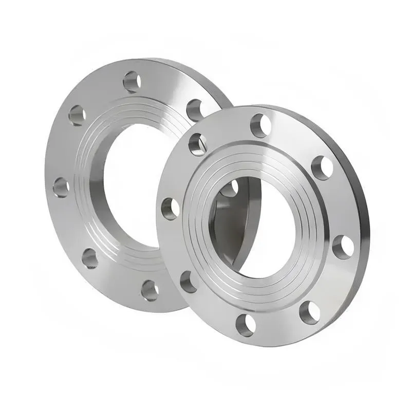
A flange—also referred to as a flange plate or rim—is a component used to connect shafts to one another, or, more commonly, to join the ends of pipes. Flanges are also utilized at the inlet and outlet ports of equipment to facilitate connections between two devices—for instance, the flange on a speed reducer. A "flange connection" or "flanged joint" refers to a detachable joint assembly comprising three interconnected elements—a flange, a gasket, and bolts—that together form a sealed structural unit. In the context of piping systems, a "pipe flange" specifically denotes a flange used for plumbing within the installation; when applied to equipment, it refers to the inlet or outlet flange of that specific device. Flanges feature a series of holes through which bolts are inserted to securely fasten the two flanges together, while a gasket placed between the flanges ensures a leak-proof seal. Flanges are broadly categorized into three types: threaded (screw-in) flanges, welded flanges, and clamp-type flanges. Flanges are invariably used in pairs; threaded flanges are suitable for low-pressure piping applications, whereas welded flanges are required for systems operating at pressures exceeding 4 kilograms per square centimeter. A sealing gasket is inserted between the two flange plates, which are then firmly secured using bolts. The thickness of a flange—as well as the specifications of the bolts used to fasten it—vary depending on the specific pressure rating required for the application. When connecting equipment such as water pumps or valves to piping systems, the corresponding connection points on these devices are often manufactured in the shape of a matching flange; this method of attachment is also referred to as a "flange connection." Generally, any connecting component that utilizes bolts to join and seal the perimeters of two flat surfaces—such as the joints in ventilation ducts—is termed a "flange"; such components may collectively be classified as "flange-type parts." However, since such a connection often constitutes merely a *portion* of a larger device—for instance, the interface between a flange and a water pump—it would be inappropriate to classify the entire water pump itself as a "flange-type part." Conversely, smaller components—such as valves—that feature such flanged interfaces may indeed be appropriately categorized as "flange-type parts."
-:-
For detailed product information, please contact sales.
-:
Markforged D2 v2 3D PrintedTool Steel Flange, Heat-Treated Product Information
-:-
For detailed product information, please contact sales.
-:
Markforged D2 v2 3D PrintedTool Steel Flange, Heat-Treated Synonyms
-:-
For detailed product information, please contact sales.
-:
Markforged D2 v2 3D PrintedTool Steel, Heat-Treated Product Information
-:-
For detailed product information, please contact sales.
-:
# **Product Introduction: Markforged D2 v2 3D Printed Tool Steel (Heat-Treated)**
## **1. Overview**
**Markforged D2 v2 3D Printed Tool Steel** is an advanced **additively manufactured (AM) version of the high-carbon, high-chromium cold work tool steel**, produced via the second-generation **Metal Fused Filament Fabrication (Metal FFF)** process followed by rigorous thermal processing. This material digitally replicates the renowned **AISI D2 (UNS T30402)** alloy, engineered to deliver **exceptional wear resistance and high hardness in complex, monolithic geometries** unattainable through conventional manufacturing. The "v2" designation signifies an evolved formulation and process optimized for improved **sintered density, reduced porosity, and more consistent mechanical properties** compared to earlier iterations. It enables the production of durable tooling inserts, wear parts, and forming dies with intricate internal features like conformal cooling, making it a strategic material for extending service life and solving thermal management challenges in demanding production environments.
## **2. Manufacturing Process & Specifications**
This material is defined by Markforged's proprietary digital manufacturing ecosystem and subsequent thermal cycles.
* **Primary Manufacturing Process:**
* **Markforged Metal FFF v2 Process (Metal X System):** An advanced two-stage additive manufacturing workflow:
1. **Printing:** Precise extrusion of a D2 tool steel powder-filled polymer filament to build a "green" part layer by layer.
2. **Post-Processing:**
* **Wash (Debinding):** Removal of the primary polymer binder in a Wash-1 station.
* **Sinter:** High-temperature furnace cycle to remove residual binders and fuse metal particles into a near-full-density solid. This results in the "brown" part.
* **Mandatory Final Heat Treatment:** The sintered part **must undergo** a complete **austenitize, quench, and temper (AQT) cycle** in a controlled atmosphere (vacuum or argon) furnace to develop the final martensitic microstructure with secondary carbides, achieving the high hardness and wear resistance characteristic of D2 tool steel.
* **Material Classification:**
* **Type:** **Additively Manufactured D2-Type Tool Steel (Second Generation)**.
* **Standard Reference:** Targets the chemistry and performance envelope of **ASTM A681 AISI D2 / UNS T30402**, but **properties are process- and geometry-dependent**. Markforged provides **guaranteed minimum** mechanical property data for standardized test artifacts.
* **Industry Context:** Competes with other AM-processed high-carbon, high-chromium steels from Binder Jetting (BJT) and Laser Powder Bed Fusion (LPBF) technologies, offering a specific balance of cost, surface finish, and ease of operation.
## **3. Chemical Composition (Weight %, Target)**
The feedstock is engineered to yield a post-sintering chemistry that closely matches standard D2 specifications.
| Element | Target Range (%) (Post-Sintering) | Role in D2 |
|---------|-----------------------------------|------------|
| **Carbon (C)** | ~1.40 – 1.60 | Forms chromium carbides for extreme wear resistance. Sintering atmosphere is critical for carbon control. |
| **Chromium (Cr)** | ~11.00 – 13.00 | Primary alloy; forms hard Cr₇C₃ carbides and provides hardenability. |
| **Molybdenum (Mo)** | ~0.70 – 1.20 | Enhances hardenability, toughness, and tempering resistance. |
| **Vanadium (V)** | ~0.50 – 1.10 | Forms ultra-hard VC carbides for added wear resistance and grain refinement. |
| **Manganese (Mn)** | ~0.20 – 0.60 | Aids hardenability. |
| **Iron (Fe)** | Balance. | |
## **4. Typical Physical & Mechanical Properties (As Printed & Heat Treated)**
* **Critical Note on Anisotropy:** Like all layer-based AM processes, properties are **directionally dependent**. Strength and ductility are typically highest in the plane of printing (XY) and lower in the build direction (Z).
* **Density:** >99% of theoretical density post-sintering (with potential for optional Hot Isostatic Pressing (HIP) to achieve 100% and improve toughness).
* **As-Sintered Condition:** Relatively soft, allowing for machining, drilling, or EDM to add final features before the hardening heat treatment.
* **After Final Heat Treatment (Typical Values for Optimal XY Orientation):**
* **Hardness:** **58 – 62+ HRC** (achievable with proper AQT cycle). The high alloy content supports high hardness.
* **Ultimate Tensile Strength (UTS):** **1600 – 1900 MPa** (232,000 – 275,000 psi). *[Guaranteed minimums are lower, e.g., ~1500 MPa].*
* **Yield Strength (0.2% Offset):** **1400 – 1700 MPa** (203,000 – 246,000 psi).
* **Elongation at Break:** **< 2%.** **Very low ductility** is a hallmark of both wrought and AM D2, but the AM microstructure (sinter necks, potential micro-porosity) can make it more brittle than its wrought counterpart.
* **Impact Toughness:** **Low.** D2 is inherently brittle; the AM process does not improve this. Not suitable for shock or impact loading.
* **Wear/Abrasion Resistance:** **Excellent.** The primary reason for selecting this material. The high volume of chromium and vanadium carbides in the hardened matrix provides outstanding resistance to abrasive wear.
* **Dimensional Change:** Significant and predictable shrinkage occurs during sintering (~17-20%). The heat treatment step also causes dimensional changes that must be accounted for in the initial CAD design.
## **5. Product Application**
Ideal for **complex, wear-intensive tooling components** where geometry-driven performance outweighs the need for high toughness.
* **Wear-Resistant Tooling Inserts:**
* **Injection mold cores/cavities** for abrasive plastics (glass-filled, mineral-filled) featuring **conformal cooling channels** to manage heat and further extend life.
* **Blanking, punching, and forming die inserts** with complex internal cooling or lightweight structures.
* **Custom Wear Parts & Tooling:**
* **Nozzles, liners, and guides** for abrasive media handling.
* **Cutting blades, slitters, and knives** with optimized geometries.
* **Jigs and fixtures** subject to abrasive wear in high-volume production.
* **Repair & Hybrid Tooling:**
* **Replacement of worn sections** on large dies or molds with a perfectly fitting, printed insert.
* **Adding complex wear-resistant features** to a conventional base tool.
## **6. Key Features & Advantages**
* **Wear Resistance in Complex Shapes:** Delivers the legendary wear resistance of D2 in geometries that solve thermal and mechanical design challenges (conformal cooling, latticed structures).
* **Design Freedom & Integration:** Enables part consolidation, internal channels, and topology-optimized lightweight designs impossible to machine.
* **Material Efficiency & Rapid Lead Time:** Near-net-shape production reduces waste and can shorten the tooling development cycle from weeks to days.
* **Achieves Production-Grade Hardness:** Proper post-processing yields hardness levels suitable for demanding production environments.
* **Office-Compatible Process:** Metal FFF is more accessible than powder-bed systems, with safer feedstock handling.
## **7. Critical Design & Processing Considerations**
* **Inherent Brittleness:** **D2 is not a tough steel.** AM D2 v2 is equally or more brittle. **Designs must avoid tensile stress concentrations, sharp corners, and thin, unsupported sections.** The primary loading should be compressive.
* **Anisotropy is Crucial:** **Orient the part so that the primary applied loads lie within the XY printing plane.** The Z-direction is the weakest.
* **Complex, Mandatory Post-Processing:** The journey from "green" part to finished tool involves **Wash, Sinter, and Heat Treatment** in separate, specialized equipment. This requires significant time, expertise, and adds cost.
* **Shrinkage & Distortion:** Sintering shrinkage is large and must be compensated for in the initial CAD model via scaling. Heat treatment can also induce distortion.
* **Surface Finish & Porosity:** As-sintered surfaces have a characteristic texture and may contain micro-porosity. Critical functional surfaces may require finishing (grinding, polishing) or surface enhancement (nitriding, PVD coating).
* **Not a Wrought Replacement:** It is a **complement** to conventional D2, best used for applications leveraging its geometric advantages, not for replacing a simple, solid D2 punch or die block.
**Summary:**
Markforged D2 v2 3D Printed Tool Steel is a specialized digital manufacturing solution for **extreme wear problems in complex geometries.** It brings the unmatched abrasion resistance of D2 into the realm of additive design, allowing engineers to create tools that not only last longer but also perform better through integrated cooling and optimized structures. Its successful application requires a clear understanding of its limitations—primarily low toughness and anisotropic behavior—and a design philosophy that exploits its strengths while meticulously avoiding its weaknesses. For the right application, such as a conformally cooled mold insert for abrasive plastics, it represents a transformative leap in tooling performance and longevity.
-:-
For detailed product information, please contact sales.
-:
Markforged D2 v2 3D PrintedTool Steel, Heat-Treated Specification
Dimensions
Size:
Diameter 20-1000 mm Length <7062 mm
Size:We can customized as required
Standard:
Per your request or drawing
We can customized as required
Properties(Theoretical)
Chemical Composition
-:-
For detailed product information, please contact sales.
-:
Markforged D2 v2 3D PrintedTool Steel, Heat-Treated Properties
-:-
For detailed product information, please contact sales.
-:
Applications of Markforged D2 v2 3D PrintedTool Steel Flange, Heat-Treated
-:-
For detailed product information, please contact sales.
-:
Chemical Identifiers Markforged D2 v2 3D PrintedTool Steel Flange, Heat-Treated
-:-
For detailed product information, please contact sales.
-:
Packing of Markforged D2 v2 3D PrintedTool Steel Flange, Heat-Treated
-:-
For detailed product information, please contact sales.
-:
Standard Packing:
-:-
For detailed product information, please contact sales.
-:
Typical bulk packaging includes palletized plastic 5 gallon/25 kg. pails, fiber and Steel Flange drums to 1 ton super sacks in full container (FCL) or truck load (T/L) quantities. Research and sample quantities and hygroscopic, oxidizing or other air sensitive materials may be packaged under argon or vacuum. Solutions are packaged in polypropylene, plastic or glass jars up to palletized 3533 gallon liquid totes Special package is available on request. E FORUs’ is carefully handled to minimize damage during storage and transportation and to preserve the quality of our products in their original condition