1,We Manufacturing processes are primarily classified into four types:
1:Forging,
2:Casting,
3:Cutting,
4:Rolling.
2,We can manufacture in accordance with these standards.
Standards:
GB Series (Chinese Standards), JB Series (Machinery Standards), HG Series (Chemical Industry Standards), ASME B16.5 (American Standards), BS4504 (British Standards), DIN (German Standards), and JIS (Japanese Standards).
Internationally, there are two primary systems of pipe flange standards: the European system, represented by the German DIN standards (including those of the former Soviet Union), and the American system, represented by the US ANSI pipe flange standards. Other common standards include: the Chinese Ministry of Machinery Industry standards (JB series), the Ministry of Chemical Industry standards (HG series), the Chinese National Standard *GB/T 9112–9124-2010 Steel Pipe Flanges*, as well as US standards (ASME B16.5), British standards (BS4504), German standards (DIN), Japanese standards (JIS), and marine standards (CBM), among others.
The nominal pressure ratings for the PN series are designated by "PN" and comprise the following nine levels: PN2.5, PN6, PN10, PN16, PN25, PN40, PN63, PN100, and PN160.
The nominal pressure ratings for the Class series are designated by "Class" and comprise the following six levels: Class150, Class300, Class600, Class900, Class1500, and Class2500.
Flange Classification
1. **According to Chemical Industry Standards:** Flanges are classified as follows:
Plate Flat Welding Flange (PL), Necked Flat Welding Flange (SO), Necked Butt Welding Flange (WN), Integral Flange (IF), Socket Welding Flange (SW), Threaded Flange (Th), Butt Welding Ring Loose Flange (PJ/SE), Blind Flange (BL), Flat Welding Ring Loose Flange (PJ/PJ), and Lined Blind Flange (BL(s)).
2. **According to Petrochemical (SH) Industry Standards:** Flanges are classified as follows:
Threaded Flange (PL), Butt Welding Flange (WN), Flat Welding Flange (SO), Socket Welding Flange (SW), Loose Flange (LJ), and Blind Flange (no specific designation).
3. **According to Machinery (JB) Industry Standards:** Flanges are classified as follows:
Integral Flange, Butt Welding Flange, Plate Flat Welding Flange, Butt Welding Ring Plate Loose Flange, Flat Welding Ring Plate Loose Flange, Lap Joint Ring Plate Loose Flange, and Blind Flange.
4. **According to Connection Method/Type:** Flanges are classified as follows:
Plate Flat Welding Flange, Necked Flat Welding Flange, Necked Butt Welding Flange, Socket Welding Flange, Threaded Flange, Blind Flange, Necked Butt Welding Ring Loose Flange, Flat Welding Ring Loose Flange, Ring-Type Joint (RTJ) Flange and Blind Flange, Large-Diameter Plate Flange, Large-Diameter High-Neck Flange, Figure-8 Blind Plate, Butt Welding Ring Loose Flange, etc.
5. **According to the Component Being Connected:** Flanges can be classified into Vessel Flanges and Pipe Flanges.
6. **According to Structural Type:** Flanges include Integral Flanges, Threaded Flanges, Flat Welding Flanges, Butt Welding Flanges, Lap Joint (Loose/Swivel) Flanges, and Blind Flanges.
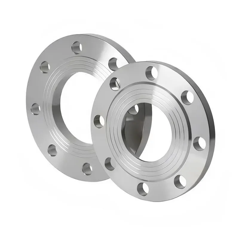
A flange—also referred to as a flange plate or rim—is a component used to connect shafts to one another, or, more commonly, to join the ends of pipes. Flanges are also utilized at the inlet and outlet ports of equipment to facilitate connections between two devices—for instance, the flange on a speed reducer. A "flange connection" or "flanged joint" refers to a detachable joint assembly comprising three interconnected elements—a flange, a gasket, and bolts—that together form a sealed structural unit. In the context of piping systems, a "pipe flange" specifically denotes a flange used for plumbing within the installation; when applied to equipment, it refers to the inlet or outlet flange of that specific device. Flanges feature a series of holes through which bolts are inserted to securely fasten the two flanges together, while a gasket placed between the flanges ensures a leak-proof seal. Flanges are broadly categorized into three types: threaded (screw-in) flanges, welded flanges, and clamp-type flanges. Flanges are invariably used in pairs; threaded flanges are suitable for low-pressure piping applications, whereas welded flanges are required for systems operating at pressures exceeding 4 kilograms per square centimeter. A sealing gasket is inserted between the two flange plates, which are then firmly secured using bolts. The thickness of a flange—as well as the specifications of the bolts used to fasten it—vary depending on the specific pressure rating required for the application. When connecting equipment such as water pumps or valves to piping systems, the corresponding connection points on these devices are often manufactured in the shape of a matching flange; this method of attachment is also referred to as a "flange connection." Generally, any connecting component that utilizes bolts to join and seal the perimeters of two flat surfaces—such as the joints in ventilation ducts—is termed a "flange"; such components may collectively be classified as "flange-type parts." However, since such a connection often constitutes merely a *portion* of a larger device—for instance, the interface between a flange and a water pump—it would be inappropriate to classify the entire water pump itself as a "flange-type part." Conversely, smaller components—such as valves—that feature such flanged interfaces may indeed be appropriately categorized as "flange-type parts."
-:-
For detailed product information, please contact sales.
-:
PSM Industries PM Krupp M-2 Powder Metallurgy Steel Flange Alloy Product Information
-:-
For detailed product information, please contact sales.
-:
PSM Industries PM Krupp M-2 Powder Metallurgy Steel Flange Alloy Synonyms
-:-
For detailed product information, please contact sales.
-:
PSM Industries PM Krupp M-2 Powder Metallurgy Steel Alloy Product Information
-:-
For detailed product information, please contact sales.
-:
# **PSM Industries PM Krupp M-2 | Premium Powder Metallurgy High-Speed Steel**
## **Overview**
PSM Industries' PM Krupp M-2 represents the gold standard in powder metallurgy (PM) high-speed steel technology, delivering a transformative advancement over conventional wrought M2 (AISI M2 / 1.3343 / HS6-5-2). Through advanced gas atomization and hot isostatic pressing (HIP) manufacturing processes, this alloy achieves an exceptionally fine, homogeneous microstructure that eliminates the carbide segregation, banding, and coarse primary carbides inherent in ingot metallurgy. The result is a material with isotropic mechanical properties, superior toughness, enhanced grindability, and consistent performance predictability. PM Krupp M-2 is engineered for high-performance cutting tools and demanding applications where edge retention, thermal resistance, and reliability under extreme conditions are critical.
## **Key Features:**
- **Ultra-Fine Homogeneous Microstructure:** Complete elimination of carbide segregation through PM processing
- **Exceptional Isotropy:** Identical properties in all directions - no transverse weakness
- **Superior Toughness:** 25-50% higher transverse rupture strength compared to conventional M2
- **Enhanced Grindability:** Reduced grinding forces, improved surface finishes, and extended wheel life
- **Excellent Red Hardness:** Maintains cutting hardness up to 540°C (1000°F)
- **Minimal Distortion:** Superior dimensional stability during heat treatment
- **High Purity:** Significantly reduced non-metallic inclusions
- **Consistent Performance:** Excellent lot-to-lot uniformity ensures predictable tool life
- **Optimized Carbide Distribution:** Fine, uniform MC and M₆C carbides (1-4 μm)
---
## **Material Specifications: PM Krupp M-2**
### **1. Chemical Composition (wt%)**
| Element | Content Range (wt%) | Function & Notes |
|---------|---------------------|------------------|
| **Carbon (C)** | 0.85 - 0.95% | Optimized for carbide formation and matrix hardness |
| **Chromium (Cr)** | 3.80 - 4.40% | Provides hardenability and wear/corrosion resistance |
| **Molybdenum (Mo)** | 4.80 - 5.50% | Primary carbide former, enhances hot hardness |
| **Tungsten (W)** | 6.00 - 6.50% | Secondary carbide former, improves red hardness |
| **Vanadium (V)** | 1.70 - 2.00% | Forms hard MC carbides for wear resistance |
| **Cobalt (Co)** | ≤ 0.50% | Optional trace amounts |
| **Silicon (Si)** | 0.20 - 0.40% | Deoxidizer and solid solution strengthener |
| **Manganese (Mn)** | 0.20 - 0.40% | Improves hardenability and strength |
| **Sulfur (S)** | ≤ 0.010% | Minimized for improved toughness |
| **Phosphorus (P)** | ≤ 0.020% | Minimized for enhanced ductility |
| **Iron (Fe)** | Balance | Matrix |
**PM-Specific Advantages:**
- **Tighter Compositional Control:** ±0.02% for critical elements
- **No Micro-segregation:** Homogeneous element distribution
- **Controlled Carbide Chemistry:** Precise MC/M₆C carbide ratios
### **2. Physical & Mechanical Properties**
#### **Physical Properties:**
| Property | Typical Value | Test Standard |
|----------|---------------|----------------|
| **Density** | 8.10 g/cm³ | ASTM B311 |
| **Melting Range** | 1430-1480°C | - |
| **Thermal Conductivity** | 24.0 W/m·K @ 20°C | ASTM E1461 |
| **Coefficient of Thermal Expansion** | 10.4 × 10⁻⁶/K (20-400°C) | ASTM E228 |
| **Modulus of Elasticity** | 220 GPa | ASTM E111 |
| **Specific Heat Capacity** | 460 J/kg·K @ 20°C | ASTM E1269 |
| **Electrical Resistivity** | 0.50 μΩ·m @ 20°C | ASTM B193 |
#### **Mechanical Properties (Hardened & Triple Tempered):**
| Tempering Condition | Hardness (HRC) | Transverse Rupture Strength (MPa) | Impact Toughness (Charpy, J) | Compressive Strength (MPa) |
|----------------------|----------------|-----------------------------------|-----------------------------|----------------------------|
| **3× 540°C** | 64-66 | 4,000-4,500 | 20-25 | 3,000-3,300 |
| **3× 560°C** | 63-65 | 4,200-4,700 | 22-28 | 2,900-3,200 |
| **3× 580°C** | 62-64 | 4,400-5,000 | 24-30 | 2,800-3,100 |
#### **High-Temperature Properties:**
| Temperature | Hot Hardness (HV) | Hot Yield Strength (MPa) | Retained Hardness (% of RT) |
|-------------|-------------------|--------------------------|------------------------------|
| **400°C** | 750-800 | 1,800-2,000 | 85-90% |
| **500°C** | 650-700 | 1,200-1,400 | 75-80% |
| **550°C** | 550-600 | 800-1,000 | 65-70% |
| **600°C** | 450-500 | 500-700 | 50-55% |
#### **Performance Comparison vs. Conventional M2:**
| Property | PM Krupp M-2 | Conventional M2 | Improvement |
|----------|--------------|-----------------|-------------|
| **Carbide Size** | 1-4 μm | 10-25 μm | 75-85% reduction |
| **Transverse Toughness** | 100% (Reference) | 60-70% | 40-50% |
| **Fatigue Life** | 100% (Reference) | 50-60% | 60-80% |
| **Wear Resistance** | 100% (Reference) | 90-95% | 5-10% |
| **Grinding Ratio** | 100% (Reference) | 50-60% | 60-80% |
### **3. Microstructural Characteristics**
- **Carbide Volume Fraction:** 10-12%
- **Average Carbide Size:** 1-4 μm (100% ≤ 6 μm)
- **Carbide Types:** MC (Vanadium-rich), M₆C (Molybdenum/Tungsten-rich)
- **Carbide Distribution:** Uniform, isotropic
- **Grain Size:** ASTM 10-12
- **Inclusion Rating:** ASTM E45: A ≤ 0.5, B ≤ 0.5, C ≤ 0.5, D ≤ 0.5
- **Microcleanliness:** ≤ 0.3% area fraction non-metallic inclusions
### **4. Applicable & Reference Standards**
- **ISO 4957:** Tool steels (Grade HS6-5-2)
- **ASTM A600:** Standard Specification for Tool Steel High Speed (Grade M2)
- **DIN 1.3343:** German standard for high-speed steel
- **JIS G4403:** High speed tool steels (Grade SKH51)
- **AMS 6491:** Aerospace Material Specification
- **UNS T11302:** Unified Numbering System
- **GB/T 9943:** Chinese standard (Grade W6Mo5Cr4V2)
- **Customer-Specific Specifications:** Widely adopted in cutting tool industries
---
## **Heat Treatment Guidelines**
### **Annealing:**
- **Temperature:** 850-870°C (1560-1600°F)
- **Soak Time:** 2-4 hours
- **Cooling Rate:** 10-20°C/hour to 600°C, then furnace cool
- **Resulting Hardness:** 220-240 HB
- **Microstructure:** Fine spheroidized carbides
### **Stress Relieving:**
- **After Rough Machining:** 600-650°C (1110-1200°F), 2 hours
- **After EDM:** 150-200°C (300-400°F) below final temper, 2-4 hours
### **Hardening:**
1. **Preheating:**
- First Stage: 450-500°C (840-930°F)
- Second Stage: 800-850°C (1470-1560°F)
2. **Austenitizing:**
- **Temperature:** 1190-1220°C (2175-2230°F)
- **Soak Time:** 2-5 minutes per 25mm thickness
- **Atmosphere:** Vacuum or salt bath preferred
3. **Quenching Options:**
- **Gas Quench:** 4-6 bar nitrogen/argon (minimal distortion)
- **Oil Quench:** Fast oil at 40-60°C
- **Salt Bath:** Marquench at 500-550°C
### **Tempering:**
- **Minimum:** Triple tempering required
- **Temperature Range:** 540-600°C (1000-1110°F)
- **Time:** 60-120 minutes per temper
- **Cooling:** Air cool between tempers
- **Cryogenic Treatment:** Optional between 1st and 2nd tempers
### **Surface Treatments:**
- **Nitriding:** Plasma or gas, 480-520°C, case depth 0.05-0.15mm
- **PVD Coatings:** Excellent adhesion for TiN, TiCN, TiAlN, AlCrN
- **Oxidation:** Steam tempering for reduced friction
---
## **Machining & Grinding**
### **Machining (Annealed Condition):**
- **Hardness:** 220-240 HB (good machinability)
- **Cutting Tools:** Carbide tools recommended
- **Turning Parameters:**
- Speed: 50-70 m/min
- Feed: 0.15-0.25 mm/rev
- Depth of Cut: 2-4 mm
- **Milling Parameters:**
- Speed: 70-90 m/min
- Feed per Tooth: 0.08-0.15 mm
- **Drilling Parameters:**
- Speed: 15-20 m/min
- Feed: 0.08-0.15 mm/rev
### **Grinding (Hardened Condition):**
- **Wheel Selection:**
- Aluminum Oxide (A): 46-60 I-J
- CBN: 80-120 concentration, vitrified bond
- **Parameters:**
- Speed: 25-30 m/s
- Feed: 0.005-0.015 mm/pass
- Cross-feed: 1-3 mm/pass
- **Coolant:** Essential - high volume, directed flow
### **Electrical Discharge Machining (EDM):**
- **Excellent Suitability:** Fine microstructure enables superior finishes
- **Wire EDM:** Multiple skim cuts for best results
- **Sinker EDM:** Graphite electrodes, fine finish settings
- **White Layer:** Typically 5-15 μm
- **Post-EDM Treatment:** Stress relieve immediately
### **Polishing:**
- **Capable of:** Fine finishes ≤ 0.02 μm Ra
- **Progression:** 220 → 320 → 400 → 600 → 800 grit
- **Final Polish:** Diamond compound for optical quality
---
## **Product Applications**
### **Metal Cutting Tools:**
- **End Mills:** Solid and indexable for steels and cast irons
- **Drills:** Twist drills, gun drills, deep hole drills
- **Reamers:** Precision hole finishing tools
- **Broaches:** Internal and surface broaching tools
- **Gear Cutters:** Hobs, shaper cutters, shaving tools
- **Threading Tools:** Taps, dies, thread mills
- **Saw Blades:** Bandsaw and circular saw blades
### **Forming Tools:**
- **Punches and Dies:** For cold forming operations
- **Extrusion Tools:** Forward and backward extrusion
- **Roll Forming Rolls:** For profile forming
- **Heading Dies:** For bolt and fastener production
### **Special Applications:**
- **Woodworking Tools:** For hardwoods and composites
- **Plastic Molding Tools:** For abrasive filled plastics
- **Knives:** Industrial cutting blades
- **Wear Parts:** Bushings, guides, wear plates
### **Industry-Specific Applications:**
- **Automotive:** Transmission components, engine parts
- **Aerospace:** Structural components, turbine parts
- **Medical:** Surgical instrument components
- **Energy:** Turbine blades, valve components
- **Die & Mold:** Injection molds, die casting dies
---
## **Quality Assurance**
### **Testing Protocol:**
1. **Chemical Analysis:** Optical emission spectroscopy (OES)
2. **Hardness Testing:** Brinell, Rockwell, microhardness
3. **Microstructural Analysis:**
- Carbide size distribution (image analysis)
- Inclusion rating per ASTM E45
- Grain size measurement
4. **Non-Destructive Testing:**
- Ultrasonic testing
- Dye penetrant inspection
5. **Mechanical Testing:** (When specified)
- Transverse rupture strength
- Impact toughness
- Fatigue testing
### **Certification:**
- **Material Certificate 3.1** per EN 10204
- **Heat Treatment Certificate**
- **Ultrasonic Test Report** (when specified)
- **Micrographic Analysis**
### **Traceability:**
- Full heat/lot traceability
- Complete processing history
- Chemical analysis certificate
- Heat treatment records
---
## **Comparative Advantages**
### **Technical Advantages:**
| Aspect | Benefit | Impact |
|--------|---------|--------|
| **Isotropic Properties** | Equal properties in all directions | Eliminates transverse weakness |
| **Fine Carbides** | 1-4 μm vs. 10-25 μm | Sharper edges, better finishes |
| **No Carbide Banding** | Uniform distribution | Consistent wear patterns |
| **Higher Toughness** | 25-50% improvement | Reduced chipping |
| **Better Grindability** | 60-80% improved ratio | Lower finishing costs |
### **Economic Benefits:**
- **Extended Tool Life:** 20-40% longer service life
- **Reduced Downtime:** More predictable performance
- **Higher Productivity:** Ability to run at higher parameters
- **Lower Total Cost:** Improved cost per part
- **Reduced Scrap:** More consistent performance
### **Performance in Specific Applications:**
- **End Mills:** 30-50% longer life in steels
- **Drills:** 20-40% improvement in difficult materials
- **Taps:** Reduced breakage in hard materials
- **Forming Tools:** Less chipping in cold forming
---
## **Technical Support Services**
PSM Industries provides:
- **Application Engineering:** Material selection and optimization
- **Heat Treatment Support:** Customized cycles
- **Failure Analysis:** Root cause determination
- **Field Performance Monitoring:** Ongoing support
- **Technical Training:** Workshops and seminars
---
**Disclaimer:** The information contained herein is based on typical data and represents general guidelines. Actual performance may vary depending on specific application conditions, heat treatment procedures, geometric factors, and operational parameters. This document does not constitute a warranty or guarantee of performance. Users should conduct appropriate testing and validation for their specific applications. PSM Industries reserves the right to modify product specifications and processing recommendations without notice. For critical applications, consultation with PSM technical personnel is strongly recommended.
-:-
For detailed product information, please contact sales.
-:
PSM Industries PM Krupp M-2 Powder Metallurgy Steel Alloy Specification
Dimensions
Size:
Diameter 20-1000 mm Length <7108 mm
Size:We can customized as required
Standard:
Per your request or drawing
We can customized as required
Properties(Theoretical)
Chemical Composition
-:-
For detailed product information, please contact sales.
-:
PSM Industries PM Krupp M-2 Powder Metallurgy Steel Alloy Properties
-:-
For detailed product information, please contact sales.
-:
Applications of PSM Industries PM Krupp M-2 Powder Metallurgy Steel Flange Alloy
-:-
For detailed product information, please contact sales.
-:
Chemical Identifiers PSM Industries PM Krupp M-2 Powder Metallurgy Steel Flange Alloy
-:-
For detailed product information, please contact sales.
-:
Packing of PSM Industries PM Krupp M-2 Powder Metallurgy Steel Flange Alloy
-:-
For detailed product information, please contact sales.
-:
Standard Packing:
-:-
For detailed product information, please contact sales.
-:
Typical bulk packaging includes palletized plastic 5 gallon/25 kg. pails, fiber and Steel Flange drums to 1 ton super sacks in full container (FCL) or truck load (T/L) quantities. Research and sample quantities and hygroscopic, oxidizing or other air sensitive materials may be packaged under argon or vacuum. Solutions are packaged in polypropylene, plastic or glass jars up to palletized 3579 gallon liquid totes Special package is available on request. E FORUs’ is carefully handled to minimize damage during storage and transportation and to preserve the quality of our products in their original condition