1,We Manufacturing processes are primarily classified into four types:
1:Forging,
2:Casting,
3:Cutting,
4:Rolling.
2,We can manufacture in accordance with these standards.
Standards:
GB Series (Chinese Standards), JB Series (Machinery Standards), HG Series (Chemical Industry Standards), ASME B16.5 (American Standards), BS4504 (British Standards), DIN (German Standards), and JIS (Japanese Standards).
Internationally, there are two primary systems of pipe flange standards: the European system, represented by the German DIN standards (including those of the former Soviet Union), and the American system, represented by the US ANSI pipe flange standards. Other common standards include: the Chinese Ministry of Machinery Industry standards (JB series), the Ministry of Chemical Industry standards (HG series), the Chinese National Standard *GB/T 9112–9124-2010 Steel Pipe Flanges*, as well as US standards (ASME B16.5), British standards (BS4504), German standards (DIN), Japanese standards (JIS), and marine standards (CBM), among others.
The nominal pressure ratings for the PN series are designated by "PN" and comprise the following nine levels: PN2.5, PN6, PN10, PN16, PN25, PN40, PN63, PN100, and PN160.
The nominal pressure ratings for the Class series are designated by "Class" and comprise the following six levels: Class150, Class300, Class600, Class900, Class1500, and Class2500.
Flange Classification
1. **According to Chemical Industry Standards:** Flanges are classified as follows:
Plate Flat Welding Flange (PL), Necked Flat Welding Flange (SO), Necked Butt Welding Flange (WN), Integral Flange (IF), Socket Welding Flange (SW), Threaded Flange (Th), Butt Welding Ring Loose Flange (PJ/SE), Blind Flange (BL), Flat Welding Ring Loose Flange (PJ/PJ), and Lined Blind Flange (BL(s)).
2. **According to Petrochemical (SH) Industry Standards:** Flanges are classified as follows:
Threaded Flange (PL), Butt Welding Flange (WN), Flat Welding Flange (SO), Socket Welding Flange (SW), Loose Flange (LJ), and Blind Flange (no specific designation).
3. **According to Machinery (JB) Industry Standards:** Flanges are classified as follows:
Integral Flange, Butt Welding Flange, Plate Flat Welding Flange, Butt Welding Ring Plate Loose Flange, Flat Welding Ring Plate Loose Flange, Lap Joint Ring Plate Loose Flange, and Blind Flange.
4. **According to Connection Method/Type:** Flanges are classified as follows:
Plate Flat Welding Flange, Necked Flat Welding Flange, Necked Butt Welding Flange, Socket Welding Flange, Threaded Flange, Blind Flange, Necked Butt Welding Ring Loose Flange, Flat Welding Ring Loose Flange, Ring-Type Joint (RTJ) Flange and Blind Flange, Large-Diameter Plate Flange, Large-Diameter High-Neck Flange, Figure-8 Blind Plate, Butt Welding Ring Loose Flange, etc.
5. **According to the Component Being Connected:** Flanges can be classified into Vessel Flanges and Pipe Flanges.
6. **According to Structural Type:** Flanges include Integral Flanges, Threaded Flanges, Flat Welding Flanges, Butt Welding Flanges, Lap Joint (Loose/Swivel) Flanges, and Blind Flanges.
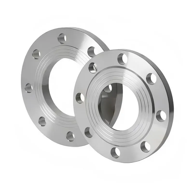
A flange—also referred to as a flange plate or rim—is a component used to connect shafts to one another, or, more commonly, to join the ends of pipes. Flanges are also utilized at the inlet and outlet ports of equipment to facilitate connections between two devices—for instance, the flange on a speed reducer. A "flange connection" or "flanged joint" refers to a detachable joint assembly comprising three interconnected elements—a flange, a gasket, and bolts—that together form a sealed structural unit. In the context of piping systems, a "pipe flange" specifically denotes a flange used for plumbing within the installation; when applied to equipment, it refers to the inlet or outlet flange of that specific device. Flanges feature a series of holes through which bolts are inserted to securely fasten the two flanges together, while a gasket placed between the flanges ensures a leak-proof seal. Flanges are broadly categorized into three types: threaded (screw-in) flanges, welded flanges, and clamp-type flanges. Flanges are invariably used in pairs; threaded flanges are suitable for low-pressure piping applications, whereas welded flanges are required for systems operating at pressures exceeding 4 kilograms per square centimeter. A sealing gasket is inserted between the two flange plates, which are then firmly secured using bolts. The thickness of a flange—as well as the specifications of the bolts used to fasten it—vary depending on the specific pressure rating required for the application. When connecting equipment such as water pumps or valves to piping systems, the corresponding connection points on these devices are often manufactured in the shape of a matching flange; this method of attachment is also referred to as a "flange connection." Generally, any connecting component that utilizes bolts to join and seal the perimeters of two flat surfaces—such as the joints in ventilation ducts—is termed a "flange"; such components may collectively be classified as "flange-type parts." However, since such a connection often constitutes merely a *portion* of a larger device—for instance, the interface between a flange and a water pump—it would be inappropriate to classify the entire water pump itself as a "flange-type part." Conversely, smaller components—such as valves—that feature such flanged interfaces may indeed be appropriately categorized as "flange-type parts."
-:-
For detailed product information, please contact sales.
-:
Sandvik Osprey A6 Tool Steel Flange Powder Product Information
-:-
For detailed product information, please contact sales.
-:
Sandvik Osprey A6 Tool Steel Flange Powder Synonyms
-:-
For detailed product information, please contact sales.
-:
Sandvik Osprey A6 Tool Steel Powder Product Information
-:-
For detailed product information, please contact sales.
-:
# **Sandvik Osprey™ A6 Tool Steel Powder | Premium Gas-Atomized Tool Steel Powder for Additive Manufacturing**
## **Overview**
Sandvik Osprey™ A6 is a high-performance, gas-atomized tool steel powder specifically engineered for additive manufacturing (AM) processes, particularly Laser Powder Bed Fusion (L-PBF) and Direct Energy Deposition (DED). This proprietary powder composition builds upon the legacy of the established AISI A6 air-hardening, medium-alloy cold work tool steel, but has been meticulously optimized for the unique thermal dynamics and solidification characteristics of AM processes. Through Sandvik's advanced gas atomization technology, Osprey™ A6 delivers exceptional powder characteristics—**high sphericity, controlled particle size distribution, minimal satellite particles, and low oxygen content**—enabling the production of complex, high-density tooling components with superior mechanical properties directly from digital designs.
## **Key Features:**
- **AM-Optimized Chemistry:** Modified from standard A6 to enhance processability in AM while retaining desirable tool steel properties
- **Exceptional Powder Quality:** High sphericity (>95%), controlled particle size distribution, minimal satellites
- **Excellent Flowability:** Designed for reliable, consistent powder spreading in L-PBF systems
- **Low Oxygen Content:** Typically <100 ppm, minimizing oxide formation during processing
- **High Recyclability:** Maintains consistent properties over multiple reuse cycles
- **Minimal Internal Stresses:** Reduced tendency for cracking during AM build process
- **Excellent As-Built Surface Finish:** Optimized for minimal post-processing
- **Comprehensive Traceability:** Full batch documentation and quality certification
- **Broad Process Compatibility:** Optimized for L-PBF (SLM, DMLS) and compatible with DED processes
---
## **Material Specifications: Osprey™ A6**
### **1. Chemical Composition (wt%)**
| Element | Content Range (wt%) | Function & AM-Specific Considerations |
|---------|---------------------|--------------------------------------|
| **Carbon (C)** | 0.65 - 0.75% | Balanced for carbide formation while minimizing cracking risk in AM |
| **Manganese (Mn)** | 1.80 - 2.20% | Enhances hardenability and strength; optimized for AM solidification |
| **Chromium (Cr)** | 0.90 - 1.20% | Provides moderate corrosion resistance and hardenability |
| **Molybdenum (Mo)** | 0.90 - 1.10% | Improves hardenability and tempering resistance |
| **Silicon (Si)** | 0.10 - 0.30% | Controlled for deoxidation and fluidity during atomization |
| **Nickel (Ni)** | 0.25 - 0.45% | Enhances toughness and hardenability |
| **Vanadium (V)** | 0.15 - 0.25% | Forms fine carbides; grain refinement |
| **Oxygen (O)** | ≤ 0.010% | Minimized to reduce oxide inclusions |
| **Nitrogen (N)** | ≤ 0.010% | Controlled to prevent porosity |
| **Iron (Fe)** | Balance | Matrix |
**AM-Specific Composition Optimizations:**
- **Reduced Carbon Range:** Narrower than conventional A6 to minimize solidification cracking
- **Manganese Enhancement:** Slightly elevated for improved hardenability without excessive alloying
- **Silicon Control:** Optimized for powder production and melt pool stability
- **Low Gas Content:** Oxygen and nitrogen minimized for high-density builds
### **2. Powder Characteristics**
#### **Physical Powder Properties:**
| Property | Specification | Test Method |
|----------|---------------|-------------|
| **Particle Size Distribution** | 15-53 μm (D10: 18-25 μm, D50: 30-38 μm, D90: 45-52 μm) | ISO 13320 |
| **Apparent Density** | 4.0 - 4.3 g/cm³ | ISO 3923-1 |
| **Tap Density** | 4.4 - 4.7 g/cm³ | ISO 3953 |
| **Flowability (Hall Flowmeter)** | ≤ 25 s/50g | ISO 4490 |
| **Sphericity** | > 95% | Image Analysis |
| **Satellite Particles** | < 3% by count | SEM Analysis |
| **Hausner Ratio** | 1.10 - 1.15 | Calculated |
| **Moisture Content** | < 0.02% | Karl Fischer |
#### **Chemical Powder Properties:**
- **Oxygen Content:** Typically 50-80 ppm
- **Nitrogen Content:** Typically 20-50 ppm
- **Hydrogen Content:** < 10 ppm
- **Metallic Impurities:** Each < 0.05%
- **Non-Metallic Inclusions:** Minimal, BSE-SEM verified
### **3. As-Built Material Properties**
#### **As-Built Condition (L-PBF, No Heat Treatment):**
| Property | Typical Value | Test Standard |
|----------|---------------|----------------|
| **Relative Density** | > 99.5% | ASTM E2858 |
| **Hardness** | 38-42 HRC | ASTM E18 |
| **Ultimate Tensile Strength** | 1,300-1,500 MPa | ASTM E8 |
| **Yield Strength (0.2%)** | 1,100-1,300 MPa | ASTM E8 |
| **Elongation at Break** | 3-6% | ASTM E8 |
| **Young's Modulus** | 190-210 GPa | ASTM E111 |
#### **Heat Treated Condition (Hardened & Tempered):**
| Condition | Hardness (HRC) | UTS (MPa) | Impact Toughness (J) |
|-----------|----------------|-----------|----------------------|
| **Annealed** | 18-22 HRC | 600-700 | 40-60 |
| **Hardened (Air)** | 62-64 HRC | 2,000-2,200 | 8-12 |
| **Tempered @ 200°C** | 60-62 HRC | 1,900-2,100 | 10-14 |
| **Tempered @ 400°C** | 58-60 HRC | 1,800-2,000 | 12-16 |
| **Tempered @ 500°C** | 54-56 HRC | 1,600-1,800 | 16-20 |
#### **Comparison to Conventional A6:**
| Property | Osprey™ A6 (AM) | Conventional A6 (Wrought) | Difference |
|----------|-----------------|--------------------------|------------|
| **As-Built Hardness** | 38-42 HRC | 18-22 HRC (annealed) | +20 HRC |
| **Max Hardness** | 62-64 HRC | 62-64 HRC | Comparable |
| **Tensile Strength** | 95-100% | 100% (reference) | Slightly lower |
| **Impact Toughness** | 80-90% | 100% (reference) | Slightly lower |
| **Isotropy Ratio** | 0.85-0.95 | 1.0 | Mild anisotropy |
### **4. Microstructural Characteristics (As-Built L-PBF)**
- **Microstructure:** Fine cellular/dendritic structure with minimal epitaxial growth
- **Cell Size:** 0.5-2.0 μm (significantly finer than wrought)
- **Grain Structure:** Columnar grains in build direction, equiaxed in transverse
- **Porosity:** < 0.5% (typically spherical gas pores)
- **Lack of Fusion:** < 0.1% with optimized parameters
- **Surface Roughness:** As-built Ra 10-20 μm, reducible to Ra 1-5 μm with optimized parameters
### **5. Post-Processing Requirements**
- **Stress Relief:** 600-650°C for 2 hours (mandatory after build)
- **Hot Isostatic Pressing (HIP):** Optional: 1150°C @ 100 MPa, 3 hours
- **Machinability:** Annealed condition: 180-220 HB, good machinability
- **Surface Finishing:** Responds well to machining, grinding, EDM, polishing
---
## **Additive Manufacturing Process Parameters**
### **Recommended L-PBF Parameters:**
| Parameter | Typical Range | Notes |
|-----------|---------------|-------|
| **Laser Power** | 180-280 W | Depends on machine and layer thickness |
| **Scan Speed** | 800-1400 mm/s | Optimized for minimal porosity |
| **Layer Thickness** | 30-50 μm | 40 μm recommended |
| **Hatch Spacing** | 90-120 μm | 110 μm typical |
| **Scan Strategy** | 67° rotation between layers | Reduces texture and anisotropy |
| **Preheat Temperature** | 100-200°C | Reduces residual stress |
| **Atmosphere** | Argon, O₂ < 100 ppm | Critical for low oxygen pickup |
### **Build Characteristics:**
- **Maximum Build Rate:** 5-10 cm³/hour (machine dependent)
- **Feature Resolution:** Down to 200 μm features achievable
- **Overhang Performance:** Up to 45° without supports (with optimized parameters)
- **Support Removal:** Good, but recommended for overhangs < 45°
### **Quality Assurance During Build:**
- **In-situ Monitoring:** Compatible with common melt pool monitoring systems
- **Layerwise Control:** Powder bed monitoring recommended
- **Atmosphere Control:** Continuous oxygen monitoring essential
---
## **Product Applications**
### **Tooling & Molds:**
- **Injection Molds:** With conformal cooling channels for reduced cycle times
- **Die Casting Inserts:** For aluminum and zinc alloys
- **Stamping & Forming Tools:** Progressive dies, bending tools
- **Blow Molds:** For PET and other plastics
### **Specialty Tooling Components:**
- **Complex Cutting Tools:** End mills, drills with internal cooling
- **Fixtures & Jigs:** Lightweight, optimized designs
- **Gauges & Measuring Tools:** High-wear components
- **Wear Parts:** Guides, bushings, wear plates
### **Industrial Applications:**
- **Automotive:** Prototype tooling, low-volume production tools
- **Aerospace:** Composite tooling, assembly fixtures
- **Medical:** Surgical instrument molds, custom tooling
- **Consumer Goods:** Packaging molds, appliance components
### **Specific AM Advantages Utilized:**
| Application Feature | Benefit | Typical Improvement |
|--------------------|---------|---------------------|
| **Conformal Cooling** | Reduced cycle time | 20-40% faster cycles |
| **Lightweight Design** | Reduced tool weight | 30-50% weight reduction |
| **Integrated Features** | Reduced assembly | Fewer components |
| **Topology Optimization** | Improved stiffness/weight | Better performance |
---
## **Standards & Certifications**
### **Applicable Standards:**
- **ISO/ASTM 52900:** Additive manufacturing - General principles
- **ISO 17296-3:** Additive manufacturing - Part 3: Main characteristics
- **ASTM F3049:** Standard guide for characterizing properties of metal powders
- **ASTM F3184:** Standard specification for additive manufacturing stainless steel
- **ISO 4957:** Tool steels (reference for A6 composition)
- **Customer-Specific Standards:** Qualified for various industry specifications
### **Quality Certifications:**
- **Batch Certification:** Each lot fully characterized
- **Traceability:** Full chemical and process history
- **Powder Reuse Documentation:** Performance over multiple cycles
- **AM Process Parameters:** Validated build parameters provided
### **Industry Qualifications:**
- **Aerospace:** Qualified under various customer programs
- **Medical:** Biocompatibility testing available
- **Automotive:** Meets major OEM material specifications
- **Tool & Die:** Accepted by major mold-making companies
---
## **Technical Support**
Sandvik provides comprehensive support for Osprey™ A6:
- **Parameter Development:** Machine-specific parameter optimization
- **Design for AM:** Consulting on tooling design optimization
- **Powder Management:** Best practices for handling and recycling
- **Training:** Workshops on AM with tool steel powders
- **Application Engineering:** Specific application development
---
## **Safety & Handling**
### **Powder Handling:**
- **Storage:** Inert atmosphere or dry air recommended
- **Handling:** Use appropriate PPE (gloves, eye protection, respirator)
- **Ventilation:** Local exhaust ventilation required
- **Fire Safety:** Class D fire extinguisher required
### **MSDS Compliance:**
- **EU:** REACH compliant
- **USA:** OSHA compliant
- **Global:** GHS compliant labeling
---
## **Economic Considerations**
### **Cost Analysis:**
| Factor | Consideration | Impact |
|--------|---------------|--------|
| **Powder Cost** | Premium pricing | Higher initial cost |
| **Powder Reuse** | 10+ cycles possible | Reduced effective cost |
| **Tool Performance** | Extended tool life | Long-term savings |
| **Production Efficiency** | Reduced cycle times | Operational savings |
| **Design Freedom** | New capabilities | Competitive advantage |
### **Return on Investment:**
- **Typical ROI Period:** 6-18 months depending on application
- **Tool Life Improvement:** 20-50% over conventional in optimized applications
- **Production Cost Reduction:** 15-30% in high-volume applications
---
**Disclaimer:** The information provided is based on typical laboratory data and field experience. Actual performance may vary depending on specific AM equipment, process parameters, part geometry, and post-processing. Users should conduct their own validation for critical applications. Sandvik reserves the right to modify specifications without notice. Osprey™ is a trademark of Sandvik AB. Always follow manufacturer's safety guidelines and local regulations when handling metal powders.
-:-
For detailed product information, please contact sales.
-:
Sandvik Osprey A6 Tool Steel Powder Specification
Dimensions
Size:
Diameter 20-1000 mm Length <7116 mm
Size:We can customized as required
Standard:
Per your request or drawing
We can customized as required
Properties(Theoretical)
Chemical Composition
-:-
For detailed product information, please contact sales.
-:
Sandvik Osprey A6 Tool Steel Powder Properties
-:-
For detailed product information, please contact sales.
-:
Applications of Sandvik Osprey A6 Tool Steel Flange Powder
-:-
For detailed product information, please contact sales.
-:
Chemical Identifiers Sandvik Osprey A6 Tool Steel Flange Powder
-:-
For detailed product information, please contact sales.
-:
Packing of Sandvik Osprey A6 Tool Steel Flange Powder
-:-
For detailed product information, please contact sales.
-:
Standard Packing:
-:-
For detailed product information, please contact sales.
-:
Typical bulk packaging includes palletized plastic 5 gallon/25 kg. pails, fiber and Steel Flange drums to 1 ton super sacks in full container (FCL) or truck load (T/L) quantities. Research and sample quantities and hygroscopic, oxidizing or other air sensitive materials may be packaged under argon or vacuum. Solutions are packaged in polypropylene, plastic or glass jars up to palletized 3587 gallon liquid totes Special package is available on request. E FORUs’ is carefully handled to minimize damage during storage and transportation and to preserve the quality of our products in their original condition