1,We Manufacturing processes are primarily classified into four types:
1:Forging,
2:Casting,
3:Cutting,
4:Rolling.
2,We can manufacture in accordance with these standards.
Standards:
GB Series (Chinese Standards), JB Series (Machinery Standards), HG Series (Chemical Industry Standards), ASME B16.5 (American Standards), BS4504 (British Standards), DIN (German Standards), and JIS (Japanese Standards).
Internationally, there are two primary systems of pipe flange standards: the European system, represented by the German DIN standards (including those of the former Soviet Union), and the American system, represented by the US ANSI pipe flange standards. Other common standards include: the Chinese Ministry of Machinery Industry standards (JB series), the Ministry of Chemical Industry standards (HG series), the Chinese National Standard *GB/T 9112–9124-2010 Steel Pipe Flanges*, as well as US standards (ASME B16.5), British standards (BS4504), German standards (DIN), Japanese standards (JIS), and marine standards (CBM), among others.
The nominal pressure ratings for the PN series are designated by "PN" and comprise the following nine levels: PN2.5, PN6, PN10, PN16, PN25, PN40, PN63, PN100, and PN160.
The nominal pressure ratings for the Class series are designated by "Class" and comprise the following six levels: Class150, Class300, Class600, Class900, Class1500, and Class2500.
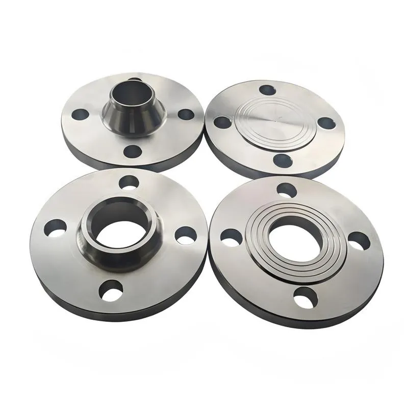
Flange Classification
1. **According to Chemical Industry Standards:** Flanges are classified as follows:
Plate Flat Welding Flange (PL), Necked Flat Welding Flange (SO), Necked Butt Welding Flange (WN), Integral Flange (IF), Socket Welding Flange (SW), Threaded Flange (Th), Butt Welding Ring Loose Flange (PJ/SE), Blind Flange (BL), Flat Welding Ring Loose Flange (PJ/PJ), and Lined Blind Flange (BL(s)).
2. **According to Petrochemical (SH) Industry Standards:** Flanges are classified as follows:
Threaded Flange (PL), Butt Welding Flange (WN), Flat Welding Flange (SO), Socket Welding Flange (SW), Loose Flange (LJ), and Blind Flange (no specific designation).
3. **According to Machinery (JB) Industry Standards:** Flanges are classified as follows:
Integral Flange, Butt Welding Flange, Plate Flat Welding Flange, Butt Welding Ring Plate Loose Flange, Flat Welding Ring Plate Loose Flange, Lap Joint Ring Plate Loose Flange, and Blind Flange.
4. **According to Connection Method/Type:** Flanges are classified as follows:
Plate Flat Welding Flange, Necked Flat Welding Flange, Necked Butt Welding Flange, Socket Welding Flange, Threaded Flange, Blind Flange, Necked Butt Welding Ring Loose Flange, Flat Welding Ring Loose Flange, Ring-Type Joint (RTJ) Flange and Blind Flange, Large-Diameter Plate Flange, Large-Diameter High-Neck Flange, Figure-8 Blind Plate, Butt Welding Ring Loose Flange, etc.
5. **According to the Component Being Connected:** Flanges can be classified into Vessel Flanges and Pipe Flanges.
6. **According to Structural Type:** Flanges include Integral Flanges, Threaded Flanges, Flat Welding Flanges, Butt Welding Flanges, Lap Joint (Loose/Swivel) Flanges, and Blind Flanges.
A flange—also referred to as a flange plate or rim—is a component used to connect shafts to one another, or, more commonly, to join the ends of pipes. Flanges are also utilized at the inlet and outlet ports of equipment to facilitate connections between two devices—for instance, the flange on a speed reducer. A "flange connection" or "flanged joint" refers to a detachable joint assembly comprising three interconnected elements—a flange, a gasket, and bolts—that together form a sealed structural unit. In the context of piping systems, a "pipe flange" specifically denotes a flange used for plumbing within the installation; when applied to equipment, it refers to the inlet or outlet flange of that specific device. Flanges feature a series of holes through which bolts are inserted to securely fasten the two flanges together, while a gasket placed between the flanges ensures a leak-proof seal. Flanges are broadly categorized into three types: threaded (screw-in) flanges, welded flanges, and clamp-type flanges. Flanges are invariably used in pairs; threaded flanges are suitable for low-pressure piping applications, whereas welded flanges are required for systems operating at pressures exceeding 4 kilograms per square centimeter. A sealing gasket is inserted between the two flange plates, which are then firmly secured using bolts. The thickness of a flange—as well as the specifications of the bolts used to fasten it—vary depending on the specific pressure rating required for the application. When connecting equipment such as water pumps or valves to piping systems, the corresponding connection points on these devices are often manufactured in the shape of a matching flange; this method of attachment is also referred to as a "flange connection." Generally, any connecting component that utilizes bolts to join and seal the perimeters of two flat surfaces—such as the joints in ventilation ducts—is termed a "flange"; such components may collectively be classified as "flange-type parts." However, since such a connection often constitutes merely a *portion* of a larger device—for instance, the interface between a flange and a water pump—it would be inappropriate to classify the entire water pump itself as a "flange-type part." Conversely, smaller components—such as valves—that feature such flanged interfaces may indeed be appropriately categorized as "flange-type parts."
-:-
For detailed product information, please contact sales.
-:
High Silicon Ductile Iron Flange at RT 4Si-2.5Mo nominal alloy content Product Information
-:-
For detailed product information, please contact sales.
-:
High Silicon Ductile Iron Flange at RT 4Si-2.5Mo nominal alloy content Synonyms
-:-
For detailed product information, please contact sales.
-:
High Silicon Ductile Iron at RT 4Si-2.5Mo nominal alloy content Product Information
-:-
For detailed product information, please contact sales.
-:
# **Product Technical Data Sheet: High Silicon Ductile Iron – RT Series (Nominal 4% Si - 2.5% Mo Alloy)**
---
## **1. Product Overview**
**High Silicon Ductile Iron (HSDI) with nominal 4% Silicon and 2.5% Molybdenum (4Si-2.5Mo)** represents the **absolute pinnacle of ferritic ductile iron technology**, pushing beyond conventional alloy limits into the domain of **specialized ultra-high-temperature materials**. This experimental-grade alloy combines extreme solid-solution strengthening with maximum precipitation hardening to create a material with **unprecedented creep resistance, exceptional microstructural stability, and sustained load-bearing capacity at temperatures approaching 950°C (1742°F)**. Operating at the very boundary of ferritic phase stability, this alloy serves as a **cost-optimized alternative to certain nickel-based superalloys and specialized heat-resistant steels** in the most demanding thermal-mechanical applications where conventional ferritic materials fail.
---
## **2. Governing Standards & Specifications**
This alloy operates in a realm beyond standard commercial specifications, requiring customized qualification protocols.
* **Classification:** **Experimental/Proprietary Ultra-High-Performance Alloy**
* **Development Framework:** While conceptually aligned with the **ISO 1083/EN 1563** family for alloyed spheroidal graphite irons, its specification is **entirely bespoke**—typically defined through joint R&D programs between advanced foundries and end-users in extreme-service industries.
* **Reference Standards:** Primarily governed by **project-specific technical agreements**. Performance validation references:
* **ASTM E139 / ISO 204:** Creep and stress-rupture testing (long-duration mandatory)
* **ASTM E21 / ISO 6892-2:** Elevated temperature tensile testing
* **ASTM G54:** Long-term static oxidation testing
* **Customer-specific thermal cycling and component validation protocols**
---
## **3. Typical Chemical Composition**
This composition represents the practical upper limit for molybdenum in silicon-strengthened ferritic ductile iron, requiring exquisite control.
| Element | Target Range (wt.%) | Critical Role & Metallurgical Rationale |
| :--- | :--- | :--- |
| **Carbon (C)** | **2.4 - 2.8** | **Critically minimized.** Essential to balance the extreme graphitizing power of 4% Si + 2.5% Mo while preventing formation of primary molybdenum carbides that would catastrophically reduce toughness. Carbon equivalent must be tightly controlled below ~4.3. |
| **Silicon (Si)** | **3.8 - 4.2 (Nominal 4.0)** | **Fundamental ferrite stabilizer and strengthener.** Provides **intense solid-solution strengthening**, elevates Ac1 transformation temperature to **~1050°C**, and ensures formation of a continuous, self-repairing SiO₂-based protective scale. |
| **Molybdenum (Mo)** | **2.4 - 2.6 (Nominal 2.5)** | **Maximum practical precipitation strengthener.** At this concentration, Mo achieves near-saturation in ferrite, creating an **extremely dense, homogeneous dispersion of nano-scale Mo-rich carbides (M₆C, M₂₃C₆)**. This provides:
• **Maximum dislocation pinning** for creep resistance
• **Superior grain boundary stabilization**
• **Exceptional resistance to microstructural coarsening** at extreme temperatures |
| **Manganese (Mn)** | **≤ 0.05** | **Effectively eliminated.** Any detectable Mn promotes formation of complex (Mn,Mo,Si)-rich G-phase at grain boundaries, destroying high-temperature ductility and dramatically reducing creep rupture life. |
| **Phosphorus (P)** | **≤ 0.012** | **Ultra-trace levels only.** Achievable only through use of ultra-high-purity charge materials. Phosphorus segregation at grain boundaries is absolutely catastrophic in this alloy system. |
| **Magnesium (Mg)** | 0.04 - 0.08 | Requires specialized treatment with heavy rare earth support to achieve and maintain nodularity in this viscous, alloy-saturated melt. |
| **Cerium/Rare Earths** | **Mandatory and carefully balanced** | Essential for complete graphite spheroidization and comprehensive neutralization of all trace elements (Ti, Sb, Pb, Bi, Sn, As). |
| **Nickel (Ni), Copper (Cu)** | **≤ 0.05 each** | Intentionally excluded to maintain absolute ferritic matrix purity and avoid any potential for austenite stabilization. |
---
## **4. Physical & Mechanical Properties**
This alloy defines the extreme performance boundary for cast ferritic materials, with properties optimized for sustained ultra-high-temperature operation.
| Property | Typical Value (Room Temperature) | Elevated Temperature Performance (800-950°C / 1472-1742°F) |
| :--- | :--- | :--- |
| **Tensile Strength (UTS)** | **800 - 1000 MPa (116 - 145 ksi)** | **Retains ~70-85% of RT UTS at 850°C.** Unprecedented strength retention for a cast ferritic material. |
| **Yield Strength (0.2% YS)** | **650 - 850 MPa (94 - 123 ksi)** | **Retains ~75-90% of RT YS at 850°C.** Extraordinary resistance to plastic deformation under load at extreme temperatures. |
| **Elongation** | **1 - 4%** | Minimal room-temperature ductility; this is a **strength and creep-dominated alloy**. Fracture toughness requires careful design consideration. |
| **Hardness (HBW)** | 300 - 380 HBW | Extreme hardness reflecting maximal matrix strengthening. |
| **Modulus of Elasticity** | ~135 - 145 GPa | Significantly reduced due to extreme alloying. |
| **Creep & Stress Rupture** | **Exceptional/Boundary-Pushing.** The 2.5% Mo content delivers the **highest possible rupture strength** in the SiMo family. **Capable of sustained operation under significant stress at 900-950°C**—a regime where few cast ferritic materials can operate. Creep rates are among the lowest achievable in ferritic cast irons. |
| **Oxidation Resistance** | **Outstanding to 1050°C.** The protective SiO₂ scale remains effective. Some Mo may volatilize as MoO₃ at the highest temperatures, requiring atmosphere consideration in specific applications. |
| **Thermal Conductivity** | **~20-24 W/m·K** | Minimal among ferritic cast irons; thermal shock resistance requires sophisticated engineering design. |
| **Thermal Fatigue Resistance** | **Excellent (with design mitigation).** Extreme strength resists crack initiation, but very low conductivity necessitates advanced design for thermal gradient management. |
| **Microstructural Stability** | **Exceptional.** Demonstrates remarkable resistance to grain growth, phase transformation, and carbide coarsening during prolonged exposure at the upper limits of its service range (up to 10,000+ hours). |
---
## **5. Product Applications**
This alloy is reserved for the most extreme applications where performance justifies its specialized nature and cost.
* **Extreme-Performance Energy Systems:** **Critical components in next-generation concentrated solar power (CSP) receivers, advanced nuclear reactor support structures, and ultra-high-temperature heat exchangers.**
* **Aerospace & Defense (Specialized):** **Select components for hypersonic test facilities, specialized exhaust components for auxiliary power units under extreme conditions, and high-temperature fixtures for advanced manufacturing processes.**
* **Advanced Industrial Processing:** **Components for chemical vapor deposition (CVD) systems, high-temperature sintering fixtures, and specialized furnace hardware** operating continuously at 950-1100°C.
* **Ultra-High-Performance Turbocharging:** **Turbine housings for extreme-duty applications** where transient temperatures may exceed 1100°C and sustained operation at 1000°C is required.
* **Research & Development:** **Benchmark material for pushing the boundaries of ferritic cast iron capabilities** and for direct comparison with nickel-based alloys in specific application spaces.
---
## **6. Fabrication & Processing Notes**
* **Melting & Casting:** **Demands elite, research-grade foundry capability.** The extreme Mo content creates significant challenges:
• **Severely reduced fluidity** requiring specialized gating and risering
• **High tendency for micro-shrinkage and hot tearing**
• **Critical need for controlled solidification** to manage carbide distribution
**Advanced simulation and prototyping are mandatory.**
* **Heat Treatment:** Invariably requires a **sophisticated multi-stage subcritical annealing process** to:
1. Temper any as-cast carbides
2. Ensure complete ferritization
3. Optimize the precipitation and distribution of Mo-rich carbides for maximum performance.
* **Machinability:** **Effectively unmachinable in final heat-treated condition.** All significant machining **must** be completed in a specially softened condition prior to final heat treatment. Final dimensional adjustments are limited to **grinding, EDM, or abrasive processes**.
* **Weldability:** **Fundamentally unweldable for service applications.** The alloy is completely incompatible with fusion welding. **Design philosophy must be "cast-to-shape" with zero welding allowance.**
---
## **7. Ordering & Qualification Protocol**
Given its experimental nature, ordering follows a rigorous, phase-gated qualification process rather than conventional procurement.
**Phase 1: Feasibility & Specification**
* **Joint development agreement** between customer and foundry
* **Definition of application-specific performance requirements** (temperature, stress, atmosphere, life)
* **Creation of bespoke material specification**
**Phase 2: Prototype & Validation**
* **Production of test castings** with full traceability
* **Comprehensive characterization:** Full chemical analysis, microstructure analysis (including TEM for nano-precipitates), RT & HT mechanical testing
* **Extended validation testing:** Long-term creep rupture (1000+ hours), oxidation testing, component-level thermal-mechanical fatigue testing
**Phase 3: Production Qualification**
* **First-article inspection** of production-intent castings
* **Statistical process validation**
* **Final approval of production specification**
**Critical Documentation Requirements:**
* **Full metallurgical pedigree** from melt to finished part
* **Comprehensive test reports** including long-duration performance data
* **Microstructural certification** with quantitative precipitate analysis
* **100% NDT certification** (radiography, FPI)
---
## **8. Disclaimer & Considerations**
**The 4Si-2.5Mo alloy represents the practical extreme of high-silicon ductile iron technology. Its deployment requires:**
1. **Technical partnership** with foundries possessing specialized capability
2. **Substantial lead time** for development and qualification
3. **Premium cost structure** reflecting its specialized nature
4. **Sophisticated engineering design** to accommodate its unique properties
5. **Acceptance of limited ductility and fracture toughness** in favor of extreme high-temperature performance
**This material is not a drop-in replacement but a specialized solution for applications where its unique combination of properties provides irreplaceable value.**
---
**The 4Si-2.5Mo High Silicon Ductile Iron alloy represents the frontier of what is achievable with ferritic cast iron technology—a material engineered not just for high temperatures, but for the most extreme thermal-mechanical environments where conventional materials have reached their absolute limits.**
-:-
For detailed product information, please contact sales.
-:
High Silicon Ductile Iron at RT 4Si-2.5Mo nominal alloy content Specification
Dimensions
Size:
Diameter 20-1000 mm Length <6548 mm
Size:We can customized as required
Standard:
Per your request or drawing
We can customized as required
Properties(Theoretical)
Chemical Composition
-:-
For detailed product information, please contact sales.
-:
High Silicon Ductile Iron at RT 4Si-2.5Mo nominal alloy content Properties
-:-
For detailed product information, please contact sales.
-:
Applications of High Silicon Ductile Iron Flange at RT 4Si-2.5Mo nominal alloy content
-:-
For detailed product information, please contact sales.
-:
Chemical Identifiers High Silicon Ductile Iron Flange at RT 4Si-2.5Mo nominal alloy content
-:-
For detailed product information, please contact sales.
-:
Packing of High Silicon Ductile Iron Flange at RT 4Si-2.5Mo nominal alloy content
-:-
For detailed product information, please contact sales.
-:
Standard Packing:
-:-
For detailed product information, please contact sales.
-:
Typical bulk packaging includes palletized plastic 5 gallon/25 kg. pails, fiber and Steel Flange drums to 1 ton super sacks in full container (FCL) or truck load (T/L) quantities. Research and sample quantities and hygroscopic, oxidizing or other air sensitive materials may be packaged under argon or vacuum. Solutions are packaged in polypropylene, plastic or glass jars up to palletized 3019 gallon liquid totes Special package is available on request. E FORUs’ is carefully handled to minimize damage during storage and transportation and to preserve the quality of our products in their original condition


 Tool Steel Flange")