1,We Manufacturing processes are primarily classified into four types:
1:Forging,
2:Casting,
3:Cutting,
4:Rolling.
2,We can manufacture in accordance with these standards.
Standards:
GB Series (Chinese Standards), JB Series (Machinery Standards), HG Series (Chemical Industry Standards), ASME B16.5 (American Standards), BS4504 (British Standards), DIN (German Standards), and JIS (Japanese Standards).
Internationally, there are two primary systems of pipe flange standards: the European system, represented by the German DIN standards (including those of the former Soviet Union), and the American system, represented by the US ANSI pipe flange standards. Other common standards include: the Chinese Ministry of Machinery Industry standards (JB series), the Ministry of Chemical Industry standards (HG series), the Chinese National Standard *GB/T 9112–9124-2010 Steel Pipe Flanges*, as well as US standards (ASME B16.5), British standards (BS4504), German standards (DIN), Japanese standards (JIS), and marine standards (CBM), among others.
The nominal pressure ratings for the PN series are designated by "PN" and comprise the following nine levels: PN2.5, PN6, PN10, PN16, PN25, PN40, PN63, PN100, and PN160.
The nominal pressure ratings for the Class series are designated by "Class" and comprise the following six levels: Class150, Class300, Class600, Class900, Class1500, and Class2500.
Flange Classification
1. **According to Chemical Industry Standards:** Flanges are classified as follows:
Plate Flat Welding Flange (PL), Necked Flat Welding Flange (SO), Necked Butt Welding Flange (WN), Integral Flange (IF), Socket Welding Flange (SW), Threaded Flange (Th), Butt Welding Ring Loose Flange (PJ/SE), Blind Flange (BL), Flat Welding Ring Loose Flange (PJ/PJ), and Lined Blind Flange (BL(s)).
2. **According to Petrochemical (SH) Industry Standards:** Flanges are classified as follows:
Threaded Flange (PL), Butt Welding Flange (WN), Flat Welding Flange (SO), Socket Welding Flange (SW), Loose Flange (LJ), and Blind Flange (no specific designation).
3. **According to Machinery (JB) Industry Standards:** Flanges are classified as follows:
Integral Flange, Butt Welding Flange, Plate Flat Welding Flange, Butt Welding Ring Plate Loose Flange, Flat Welding Ring Plate Loose Flange, Lap Joint Ring Plate Loose Flange, and Blind Flange.
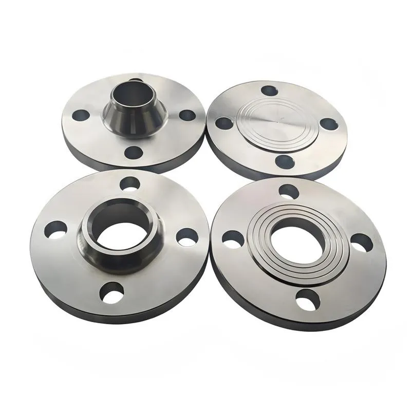
4. **According to Connection Method/Type:** Flanges are classified as follows:
Plate Flat Welding Flange, Necked Flat Welding Flange, Necked Butt Welding Flange, Socket Welding Flange, Threaded Flange, Blind Flange, Necked Butt Welding Ring Loose Flange, Flat Welding Ring Loose Flange, Ring-Type Joint (RTJ) Flange and Blind Flange, Large-Diameter Plate Flange, Large-Diameter High-Neck Flange, Figure-8 Blind Plate, Butt Welding Ring Loose Flange, etc.
5. **According to the Component Being Connected:** Flanges can be classified into Vessel Flanges and Pipe Flanges.
6. **According to Structural Type:** Flanges include Integral Flanges, Threaded Flanges, Flat Welding Flanges, Butt Welding Flanges, Lap Joint (Loose/Swivel) Flanges, and Blind Flanges.
A flange—also referred to as a flange plate or rim—is a component used to connect shafts to one another, or, more commonly, to join the ends of pipes. Flanges are also utilized at the inlet and outlet ports of equipment to facilitate connections between two devices—for instance, the flange on a speed reducer. A "flange connection" or "flanged joint" refers to a detachable joint assembly comprising three interconnected elements—a flange, a gasket, and bolts—that together form a sealed structural unit. In the context of piping systems, a "pipe flange" specifically denotes a flange used for plumbing within the installation; when applied to equipment, it refers to the inlet or outlet flange of that specific device. Flanges feature a series of holes through which bolts are inserted to securely fasten the two flanges together, while a gasket placed between the flanges ensures a leak-proof seal. Flanges are broadly categorized into three types: threaded (screw-in) flanges, welded flanges, and clamp-type flanges. Flanges are invariably used in pairs; threaded flanges are suitable for low-pressure piping applications, whereas welded flanges are required for systems operating at pressures exceeding 4 kilograms per square centimeter. A sealing gasket is inserted between the two flange plates, which are then firmly secured using bolts. The thickness of a flange—as well as the specifications of the bolts used to fasten it—vary depending on the specific pressure rating required for the application. When connecting equipment such as water pumps or valves to piping systems, the corresponding connection points on these devices are often manufactured in the shape of a matching flange; this method of attachment is also referred to as a "flange connection." Generally, any connecting component that utilizes bolts to join and seal the perimeters of two flat surfaces—such as the joints in ventilation ducts—is termed a "flange"; such components may collectively be classified as "flange-type parts." However, since such a connection often constitutes merely a *portion* of a larger device—for instance, the interface between a flange and a water pump—it would be inappropriate to classify the entire water pump itself as a "flange-type part." Conversely, smaller components—such as valves—that feature such flanged interfaces may indeed be appropriately categorized as "flange-type parts."
-:-
For detailed product information, please contact sales.
-:
High Silicon Ductile Iron Flange at RT 2.8Si-1.0Mo nominal alloy content Product Information
-:-
For detailed product information, please contact sales.
-:
High Silicon Ductile Iron Flange at RT 2.8Si-1.0Mo nominal alloy content Synonyms
-:-
For detailed product information, please contact sales.
-:
High Silicon Ductile Iron at RT 2.8Si-1.0Mo nominal alloy content Product Information
-:-
For detailed product information, please contact sales.
-:
# **Product Technical Data Sheet: High Silicon Ductile Iron – RT Series (Nominal 2.8% Si - 1.0% Mo Alloy)**
---
## **1. Product Overview**
**High Silicon Ductile Iron (HSDI) with nominal 2.8% Silicon and 1.0% Molybdenum (2.8Si-1.0Mo)** represents a **strategically balanced high-performance alloy** within the RT-series family. This composition is engineered to provide a **superior combination of enhanced elevated-temperature strength, good oxidation resistance, and notably better room-temperature ductility and toughness** compared to higher-silicon variants (e.g., 4% Si). By moderating the silicon content while maintaining a significant molybdenum addition, this alloy achieves an optimal compromise, making it suitable for applications requiring **reliable performance up to approximately 750-800°C (1382-1472°F)** where thermal cycling, moderate mechanical loads, and good fabricability are key concerns. It serves as a robust upgrade over standard ferritic ductile irons for demanding, but not extreme, high-temperature service.
---
## **2. Governing Standards & Specifications**
This alloy is typically specified under proprietary or application-focused standards, bridging commercial and high-performance grades.
* **Classification:** **Enhanced High-Temperature Ductile Iron / Engineered Alloy**
* **Industry Framework:** Aligns with the alloyed ductile iron classification in **ISO 1083 / EN 1563**. Often commercialized under designations like **SiMo 2.8-1.0** or similar proprietary codes.
* **Reference Standards:**
* **ASTM A536:** Base ductile iron specification (typically Grade 80-55-06 or similar as a starting point, with alloy modifications).
* **ASTM E8/E21:** Tensile testing (Room & Elevated Temperature).
* **ASTM E139:** Creep testing (for critical applications).
* **SAE J434:** May be referenced for automotive applications with specific alloy amendments.
---
## **3. Typical Chemical Composition**
The composition is carefully balanced to leverage the benefits of both silicon and molybdenum without the processing challenges of higher-silicon alloys.
| Element | Target Range (wt.%) | Critical Role & Metallurgical Rationale |
| :--- | :--- | :--- |
| **Carbon (C)** | **3.2 - 3.6** | Moderately controlled. Lower than standard ductile iron to partially offset the graphitizing effect of Si, but not as drastically reduced as in 4% Si alloys, aiding castability and reducing shrinkage tendency. |
| **Silicon (Si)** | **2.7 - 2.9 (Nominal 2.8)** | **Primary solid-solution strengthener and oxidation enhancer.** Provides significant strengthening of the ferrite matrix and raises the Ac1 temperature sufficiently for service up to ~800°C. Promotes a protective SiO₂ scale. This level offers a better balance between strengthening and maintaining ductility compared to 4% Si. |
| **Molybdenum (Mo)** | **0.9 - 1.1 (Nominal 1.0)** | **Key high-temperature strengthener.** Provides solid-solution strengthening and promotes the formation of fine, stable carbides (e.g., Mo₂C). **Significantly improves creep resistance and maintains yield strength at elevated temperatures.** The 1.0% level offers a substantial improvement over Mo-free grades without excessive cost or negative impact on machinability. |
| **Manganese (Mn)** | **≤ 0.30** | **Moderately low.** Controlled to minimize the formation of pearlite and complex brittle phases. Higher than in 4% Si alloys, offering some latitude in charge materials. |
| **Phosphorus (P)** | **≤ 0.035** | **Low.** Controlled to prevent grain boundary embrittlement, a critical requirement for maintaining impact toughness. |
| **Magnesium (Mg)** | 0.03 - 0.05 | Standard for ensuring full spheroidal graphite formation. |
| **Cerium (Ce)/Rare Earths** | **Often used** | Aid in nodularization and counteract trace elements. |
| **Copper (Cu)** | **≤ 0.20** | Minimized; not a primary alloying element in this grade. |
| **Nickel (Ni)** | **≤ 0.50** | May be present incidentally or added in small amounts to refine microstructure. |
---
## **4. Physical & Mechanical Properties**
This alloy offers a well-rounded set of properties, excelling in high-temperature performance while maintaining good room-temperature characteristics.
| Property | Typical Value (Room Temperature) | Elevated Temperature Performance (e.g., 600-750°C / 1112-1382°F) |
| :--- | :--- | :--- |
| **Tensile Strength (UTS)** | **550 - 700 MPa (80 - 102 ksi)** | **Retains ~50-65% of RT UTS at 700°C.** Provides a clear advantage over standard ferritic grades at temperature. |
| **Yield Strength (0.2% YS)** | **400 - 550 MPa (58 - 80 ksi)** | **Retains ~55-70% of RT YS at 700°C.** Good resistance to deformation under load at elevated temperatures. |
| **Elongation** | **10 - 20%** | **Good to very good ductility** at room temperature, a key advantage over higher-silicon variants. Provides better tolerance for stress concentrations and shock loads. |
| **Hardness (HBW)** | 200 - 250 HBW | Increased compared to standard ferritic DI due to alloy strengthening, but not excessively high. |
| **Impact Toughness (Charpy V-notch, RT)** | **15 - 30 J** | **Significantly better than 4% Si alloys.** Offers good fracture resistance, important for components subject to thermal or mechanical shock. |
| **Modulus of Elasticity** | ~160 - 170 GPa | Slightly lower than standard DI but higher than 4% Si variants. |
| **Creep Resistance** | **Very Good.** The 1.0% Mo addition provides a substantial improvement in stress rupture life and reduces creep rate at temperatures up to ~750°C compared to Si-only strengthened grades. |
| **Oxidation Resistance** | **Good to Very Good.** The 2.8% Si promotes the formation of a protective scale, offering significantly better oxidation resistance than standard DI, though not as extreme as 4% Si alloys. Effective up to **~800-850°C** in oxidizing atmospheres. |
| **Thermal Conductivity** | **~30-35 W/m·K** | Better than 4% Si alloys, improving thermal fatigue resistance by allowing heat to dissipate more readily. |
| **Thermal Fatigue Resistance** | **Very Good.** The combination of good strength, ductility, and improved conductivity provides excellent resistance to cracking under thermal cycling conditions. |
| **Microstructure** | **Predominantly Ferritic Matrix** (may contain minor pearlite depending on cooling rate) with **Spheroidal Graphite**. Fine Mo-carbides are dispersed in the matrix. |
---
## **5. Product Applications**
This alloy is well-suited for a wide range of demanding applications where improved high-temperature performance is needed without sacrificing too much room-temperature toughness or manufacturability.
* **Turbocharger Housings & Exhaust Manifolds:** For passenger car, light truck, and medium-duty diesel engines. An excellent balance for components seeing peak temperatures of 750-800°C.
* **Exhaust System Components:** **EGR coolers, exhaust diffusers, and hot-end connectors** in modern emission control systems.
* **Industrial Furnace Parts:** **Fixture components, trays, and conveyor links** for heat treatment and brazing furnaces operating in the 700-800°C range.
* **Engine Components:** **Cylinder heads for high-output engines** and other thermally stressed components where good castability and machinability are also required.
* **Valve & Pump Bodies:** For applications in power generation and chemical processing handling hot fluids.
* **General High-Temperature Structural Castings:** Where standard ductile iron is marginal, but the extreme (and more brittle) 4% Si alloys are not justified.
---
## **6. Fabrication & Processing Notes**
* **Melting & Casting:** **More forgiving than 4% Si alloys.** The lower silicon content improves fluidity and reduces shrinkage tendencies, making it easier to cast sound, complex components. Standard ductile iron foundry practices can often be adapted with proper chemistry control.
* **Heat Treatment:** Typically supplied in the **as-cast or subcritically annealed** condition to ensure a fully ferritic matrix and temper any as-cast carbides. Can also be **normalized** to achieve a pearlitic-ferritic matrix for even higher room-temperature strength if the application permits. Not typically quenched and tempered.
* **Machinability:** **Fair to Good.** More machinable than 4% Si-1.0Mo due to lower hardness and silicon content. Carbide tooling is still recommended for production efficiency, but high-speed steel can be used in some operations.
* **Weldability:** **Poor, but possible with extreme care.** While still challenging, it is generally more weldable than the 4% Si variants. If repair is absolutely necessary, it requires stringent procedures: high pre-heat (500-600°C), use of specialized nickel-iron filler metals, and controlled post-weld cooling with stress relief. **Not recommended for fabrication welding.**
---
## **7. Ordering Information**
**Specify:** **"High-Temperature Ductile Iron Castings, 2.8Si-1.0Mo Alloy (e.g., SiMo 2.8-1.0), [As-Cast or Annealed] per [Customer Drawing/Specification]."**
**Essential Details to Provide:**
* **Applicable Standard or Proprietary Alloy Designation.**
* **Required Mechanical Properties** at room temperature and, if critical, at a specified elevated temperature.
* **Heat Treatment Condition** (As-Cast, Annealed, Normalized).
* **Application Context** (e.g., max service temperature, load type).
* **Certification Requirements:** Mill Test Report (MTR) with full chemical analysis and room-temperature mechanical properties. Elevated temperature test data may be requested for qualification.
* **Quality & Inspection:** Standard foundry quality controls are typically sufficient. Dye penetrant or magnetic particle inspection may be specified for critical surfaces.
---
## **8. Value Proposition**
**The 2.8Si-1.0Mo alloy offers a compelling "sweet spot" in the high-silicon ductile iron family. It delivers a significant performance upgrade over standard grades for high-temperature service—particularly in creep and oxidation resistance—while maintaining much of the castability, machinability, and room-temperature toughness that make ductile iron a versatile engineering material. It is an ideal choice when the extreme performance (and associated challenges) of 4% Si alloys is not required, but standard ductile iron is insufficient.**
-:-
For detailed product information, please contact sales.
-:
High Silicon Ductile Iron at RT 2.8Si-1.0Mo nominal alloy content Specification
Dimensions
Size:
Diameter 20-1000 mm Length <6549 mm
Size:We can customized as required
Standard:
Per your request or drawing
We can customized as required
Properties(Theoretical)
Chemical Composition
-:-
For detailed product information, please contact sales.
-:
High Silicon Ductile Iron at RT 2.8Si-1.0Mo nominal alloy content Properties
-:-
For detailed product information, please contact sales.
-:
Applications of High Silicon Ductile Iron Flange at RT 2.8Si-1.0Mo nominal alloy content
-:-
For detailed product information, please contact sales.
-:
Chemical Identifiers High Silicon Ductile Iron Flange at RT 2.8Si-1.0Mo nominal alloy content
-:-
For detailed product information, please contact sales.
-:
Packing of High Silicon Ductile Iron Flange at RT 2.8Si-1.0Mo nominal alloy content
-:-
For detailed product information, please contact sales.
-:
Standard Packing:
-:-
For detailed product information, please contact sales.
-:
Typical bulk packaging includes palletized plastic 5 gallon/25 kg. pails, fiber and Steel Flange drums to 1 ton super sacks in full container (FCL) or truck load (T/L) quantities. Research and sample quantities and hygroscopic, oxidizing or other air sensitive materials may be packaged under argon or vacuum. Solutions are packaged in polypropylene, plastic or glass jars up to palletized 3020 gallon liquid totes Special package is available on request. E FORUs’ is carefully handled to minimize damage during storage and transportation and to preserve the quality of our products in their original condition