1,We Manufacturing processes are primarily classified into four types:
1:Forging,
2:Casting,
3:Cutting,
4:Rolling.
2,We can manufacture in accordance with these standards.
Standards:
GB Series (Chinese Standards), JB Series (Machinery Standards), HG Series (Chemical Industry Standards), ASME B16.5 (American Standards), BS4504 (British Standards), DIN (German Standards), and JIS (Japanese Standards).
Internationally, there are two primary systems of pipe flange standards: the European system, represented by the German DIN standards (including those of the former Soviet Union), and the American system, represented by the US ANSI pipe flange standards. Other common standards include: the Chinese Ministry of Machinery Industry standards (JB series), the Ministry of Chemical Industry standards (HG series), the Chinese National Standard *GB/T 9112–9124-2010 Steel Pipe Flanges*, as well as US standards (ASME B16.5), British standards (BS4504), German standards (DIN), Japanese standards (JIS), and marine standards (CBM), among others.
The nominal pressure ratings for the PN series are designated by "PN" and comprise the following nine levels: PN2.5, PN6, PN10, PN16, PN25, PN40, PN63, PN100, and PN160.
The nominal pressure ratings for the Class series are designated by "Class" and comprise the following six levels: Class150, Class300, Class600, Class900, Class1500, and Class2500.
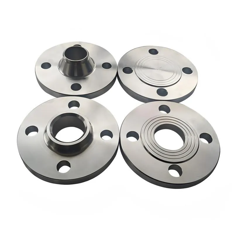
Flange Classification
1. **According to Chemical Industry Standards:** Flanges are classified as follows:
Plate Flat Welding Flange (PL), Necked Flat Welding Flange (SO), Necked Butt Welding Flange (WN), Integral Flange (IF), Socket Welding Flange (SW), Threaded Flange (Th), Butt Welding Ring Loose Flange (PJ/SE), Blind Flange (BL), Flat Welding Ring Loose Flange (PJ/PJ), and Lined Blind Flange (BL(s)).
2. **According to Petrochemical (SH) Industry Standards:** Flanges are classified as follows:
Threaded Flange (PL), Butt Welding Flange (WN), Flat Welding Flange (SO), Socket Welding Flange (SW), Loose Flange (LJ), and Blind Flange (no specific designation).
3. **According to Machinery (JB) Industry Standards:** Flanges are classified as follows:
Integral Flange, Butt Welding Flange, Plate Flat Welding Flange, Butt Welding Ring Plate Loose Flange, Flat Welding Ring Plate Loose Flange, Lap Joint Ring Plate Loose Flange, and Blind Flange.
4. **According to Connection Method/Type:** Flanges are classified as follows:
Plate Flat Welding Flange, Necked Flat Welding Flange, Necked Butt Welding Flange, Socket Welding Flange, Threaded Flange, Blind Flange, Necked Butt Welding Ring Loose Flange, Flat Welding Ring Loose Flange, Ring-Type Joint (RTJ) Flange and Blind Flange, Large-Diameter Plate Flange, Large-Diameter High-Neck Flange, Figure-8 Blind Plate, Butt Welding Ring Loose Flange, etc.
5. **According to the Component Being Connected:** Flanges can be classified into Vessel Flanges and Pipe Flanges.
6. **According to Structural Type:** Flanges include Integral Flanges, Threaded Flanges, Flat Welding Flanges, Butt Welding Flanges, Lap Joint (Loose/Swivel) Flanges, and Blind Flanges.
A flange—also referred to as a flange plate or rim—is a component used to connect shafts to one another, or, more commonly, to join the ends of pipes. Flanges are also utilized at the inlet and outlet ports of equipment to facilitate connections between two devices—for instance, the flange on a speed reducer. A "flange connection" or "flanged joint" refers to a detachable joint assembly comprising three interconnected elements—a flange, a gasket, and bolts—that together form a sealed structural unit. In the context of piping systems, a "pipe flange" specifically denotes a flange used for plumbing within the installation; when applied to equipment, it refers to the inlet or outlet flange of that specific device. Flanges feature a series of holes through which bolts are inserted to securely fasten the two flanges together, while a gasket placed between the flanges ensures a leak-proof seal. Flanges are broadly categorized into three types: threaded (screw-in) flanges, welded flanges, and clamp-type flanges. Flanges are invariably used in pairs; threaded flanges are suitable for low-pressure piping applications, whereas welded flanges are required for systems operating at pressures exceeding 4 kilograms per square centimeter. A sealing gasket is inserted between the two flange plates, which are then firmly secured using bolts. The thickness of a flange—as well as the specifications of the bolts used to fasten it—vary depending on the specific pressure rating required for the application. When connecting equipment such as water pumps or valves to piping systems, the corresponding connection points on these devices are often manufactured in the shape of a matching flange; this method of attachment is also referred to as a "flange connection." Generally, any connecting component that utilizes bolts to join and seal the perimeters of two flat surfaces—such as the joints in ventilation ducts—is termed a "flange"; such components may collectively be classified as "flange-type parts." However, since such a connection often constitutes merely a *portion* of a larger device—for instance, the interface between a flange and a water pump—it would be inappropriate to classify the entire water pump itself as a "flange-type part." Conversely, smaller components—such as valves—that feature such flanged interfaces may indeed be appropriately categorized as "flange-type parts."
-:-
For detailed product information, please contact sales.
-:
Dura-Bar 80-55-06 Continuously Cast Ductile Iron Flange Bar Stock ASTM A536 Product Information
-:-
For detailed product information, please contact sales.
-:
Dura-Bar 80-55-06 Continuously Cast Ductile Iron Flange Bar Stock ASTM A536 Synonyms
-:-
For detailed product information, please contact sales.
-:
Dura-Bar 80-55-06 Continuously Cast Ductile Iron Bar Stock ASTM A536 Product Information
-:-
For detailed product information, please contact sales.
-:
## **Product Introduction: Dura-Bar 80-55-06 Continuously Cast Ductile Iron Bar Stock**
**Dura-Bar 80-55-06** is a premium **pearlitic ductile iron** manufactured through proprietary continuous casting technology. This material meets the **ASTM A536 80-55-06** specification, representing a high-strength, wear-resistant grade that maintains the exceptional machinability and consistency characteristic of the Dura-Bar product line.
The "80-55-06" designation indicates minimum mechanical properties: **80 ksi Tensile Strength, 55 ksi Yield Strength, and 6% Elongation**. Unlike traditional sand casting, the continuous casting process creates a dense, homogeneous microstructure free from internal defects, making it ideal for high-performance applications where reliability and consistency are paramount.
---
## **1. Key International Standards & Designations**
| Standard System | Designation | Notes |
|----------------|-------------|-------|
| **Primary Standard** | **ASTM A536** (Grade 80-55-06) | Governs mechanical property requirements |
| **Manufacturer Standard** | **Dura-Bar Continuous Cast Grade 80-55-06** | Proprietary production specifications |
| **ISO Equivalent** | **EN-GJS-600-3** (ISO 1083) | Similar but not identical properties |
| **SAE Automotive** | **J434 D5506** | Closest automotive equivalent |
| **UNS** | **F34100** (typical for pearlitic grades) | Unified Numbering System |
| **Common Names** | Pearlitic Ductile Iron, High-Strength Continuous Cast Iron | Industry terminology |
---
## **2. Chemical Composition (Typical Ranges)**
The chemistry is carefully balanced to achieve a predominantly pearlitic matrix while maintaining good castability and machinability.
| Element | Range (% wt.) | Functional Purpose | Critical Notes |
|---------|--------------|-------------------|----------------|
| **Carbon (C)** | 3.4 - 3.7 | Graphite formation, castability | Lower than ferritic grades to limit graphite volume |
| **Silicon (Si)** | 2.0 - 2.5 | Graphitizer, strengthens ferrite | Controlled to prevent excessive ferrite formation |
| **Manganese (Mn)** | 0.4 - 0.8 | **Primary pearlite promoter** | Higher than 65-45-12 grade for increased pearlite |
| **Phosphorus (P)** | ≤ 0.035 | Impurity control | Minimized to prevent brittle phosphides |
| **Sulfur (S)** | ≤ 0.015 | Nodularization essential | Critical for spheroidal graphite formation |
| **Magnesium (Mg)** | 0.04 - 0.06 | **Nodularizing agent** | Ensures Type I graphite morphology |
| **Copper (Cu)** | 0.4 - 0.8 | **Pearlite stabilizer**, strengthens matrix | Key alloying element for this grade |
| **Tin (Sn)** | 0.02 - 0.05 | **Powerful pearlite stabilizer** | Ensures consistent microstructure in varying sections |
| **Molybdenum (Mo)** | 0.1 - 0.3 (optional) | Refines pearlite, increases hardenability | Added for enhanced properties in specific applications |
**Microstructural Characteristics:**
- **Matrix:** 80-95% fine pearlite with balance ferrite
- **Graphite:** ASTM Type I, Size 5-7 (well-dispersed spheres)
- **Carbide Content:** <2% (continuously cast advantage)
---
## **3. Mechanical & Physical Properties**
### **A. Mechanical Properties**
| Property | Minimum Requirement | Typical Range | Notes |
|----------|-------------------|--------------|-------|
| **Tensile Strength** | 80 ksi (552 MPa) | 85-100 ksi (586-690 MPa) | 25% stronger than 65-45-12 grade |
| **Yield Strength** | 55 ksi (379 MPa) | 60-70 ksi (414-483 MPa) | Excellent for loaded components |
| **Elongation** | 6% | 8-12% | Higher than minimum typical |
| **Hardness** | - | 217-269 HB (95-26 HRC) | Consistent across diameter |
| **Modulus of Elasticity** | - | 24.5 × 10⁶ psi (169 GPa) | Similar to other ductile irons |
| **Fatigue Strength** | - | 30-35 ksi (207-241 MPa) endurance limit | Good for cyclic loading |
| **Impact Energy** | - | 10-20 ft-lb (14-27 J) Charpy V-notch | Lower than ferritic grades but adequate |
### **B. Physical Properties**
| Property | Value | Comparative Advantage |
|----------|-------|----------------------|
| **Density** | 0.260 lb/in³ (7.19 g/cm³) | 10% lighter than steel |
| **Thermal Conductivity** | 21.6 Btu/(ft·hr·°F) @ 212°F | Excellent heat dissipation |
| **Thermal Expansion** | 6.5 × 10⁻⁶/°F (68-212°F) | Matches steel for assemblies |
| **Damping Capacity** | 5-7× greater than steel | Superior vibration absorption |
| **Specific Heat** | 0.11 Btu/(lb·°F) | - |
---
## **4. Key Characteristics & Advantages**
### **Technical Advantages**
1. **Strength-to-Weight Ratio:** Superior to most carbon steels at comparable hardness
2. **Machinability Index:** 60-70% (vs. 1212 steel = 100%)
3. **Wear Resistance:** 2-3× better than 1045 steel due to pearlitic matrix
4. **Consistency:** Hardness variation <15 HB across bar diameter
5. **Thermal Properties:** 40% better thermal conductivity than steel
### **Manufacturing Benefits**
- **Material Yield:** Near 100% utilization (no casting defects)
- **Tool Life:** 3-5× longer than machining equivalent steel
- **Production Speed:** 30-50% faster machining than steel
- **Surface Finish:** Typically 32-63 μin Ra achievable
---
## **5. Application Areas**
### **High-Strength Structural Components**
- **Hydraulic Systems:** High-pressure pump bodies, valve blocks, manifold plates
- **Power Transmission:** Medium-to-heavy duty gears, sprockets, sheaves, coupling hubs
- **Automotive:** Diesel engine components, turbocharger housings, transmission parts
- **Industrial Machinery:** Press frames, machine tool components, bearing housings
### **Wear-Resistant Applications**
- **Rolling/Sliding Contact:** Guide rails, ways, rollers, cam followers
- **Tooling:** Fixtures, jigs, dies requiring dimensional stability
- **Agricultural:** Combine harvester components, tillage tool parts
### **Specific Replacement Applications**
- Replaces **1144 Stressproof® steel** with better damping and machinability
- Alternative to **4140/4340 steel** in non-welded, high-wear applications
- Superior to **gray iron** in strength-critical applications
---
## **6. Processing & Fabrication Guidelines**
### **Machining Parameters**
| Operation | Speed (SFPM) | Feed (IPR) | Depth of Cut | Notes |
|-----------|-------------|------------|--------------|-------|
| **Turning** | 500-800 | 0.010-0.020 | 0.100-0.250" | Use C2/C3 carbide or coated inserts |
| **Drilling** | 150-300 | 0.005-0.015 | - | Peck drill for deep holes |
| **Milling** | 400-700 | 0.003-0.010 per tooth | 0.050-0.150" | Climb milling recommended |
| **Tapping** | 30-60 | - | - | Use spiral-point taps for through holes |
### **Heat Treatment Options**
- **Annealing:** Not typically required (as-supplied condition optimal)
- **Stress Relieving:** 900-1100°F (480-595°C) for 1 hr/inch, furnace cool
- **Surface Hardening:** Flame/induction hardening to 50-55 HRC possible
- **Nitriding:** Can be applied for extreme wear resistance
### **Joining & Finishing**
- **Welding:** Not recommended for structural joints; specialized procedures only
- **Adhesive Bonding:** Excellent with proper surface preparation
- **Plating:** Chrome, nickel, and zinc plating all applicable
- **Coatings:** PTFE, DLC, and other wear coatings adhere well
---
## **7. Comparative Performance Data**
### **vs. Competitive Materials**
| Material | Relative Machining Cost | Damping Capacity | Wear Resistance | Strength |
|----------|------------------------|------------------|----------------|----------|
| **Dura-Bar 80-55-06** | **1.0 (Baseline)** | **Excellent** | **Very Good** | **Very Good** |
| **1045 Steel** | 1.8-2.2× | Poor | Fair | Good |
| **1144 Steel** | 1.5-1.8× | Poor | Fair | Good |
| **Gray Iron** | 0.9-1.1× | Excellent | Fair | Poor |
| **Aluminum 6061** | 0.7-0.9× | Good | Poor | Fair |
---
## **8. Quality Assurance & Testing**
Dura-Bar 80-55-06 undergoes rigorous quality control:
- **Microstructural Analysis:** Every heat verified for graphite morphology and matrix
- **Hardness Testing:** Multiple points per bar for consistency
- **Ultrasonic Testing:** Optional for critical applications
- **Certification:** Mill test reports with full traceability
- **Lot Control:** Complete chemical and mechanical property documentation
---
## **Summary**
**Dura-Bar 80-55-06 Continuous Cast Ductile Iron** represents the optimal choice for applications demanding **high strength, excellent wear resistance, and superior manufacturability**. Its unique combination of properties—achieved through controlled chemistry and advanced continuous casting technology—makes it unparalleled for:
1. **High-performance machined components** requiring dimensional stability
2. **Wear-critical applications** where surface durability is essential
3. **Structural parts** benefiting from vibration damping
4. **Cost-sensitive production** where machining efficiency is critical
With mechanical properties approaching low-alloy steels and manufacturing advantages far exceeding them, this material provides engineers with a reliable, consistent, and cost-effective solution for demanding mechanical applications across aerospace, automotive, hydraulic, and industrial equipment sectors.
-:-
For detailed product information, please contact sales.
-:
Dura-Bar 80-55-06 Continuously Cast Ductile Iron Bar Stock ASTM A536 Specification
Dimensions
Size:
Diameter 20-1000 mm Length <6604 mm
Size:We can customized as required
Standard:
Per your request or drawing
We can customized as required
Properties(Theoretical)
Chemical Composition
-:-
For detailed product information, please contact sales.
-:
Dura-Bar 80-55-06 Continuously Cast Ductile Iron Bar Stock ASTM A536 Properties
-:-
For detailed product information, please contact sales.
-:
Applications of Dura-Bar 80-55-06 Continuously Cast Ductile Iron Flange Bar Stock ASTM A536
-:-
For detailed product information, please contact sales.
-:
Chemical Identifiers Dura-Bar 80-55-06 Continuously Cast Ductile Iron Flange Bar Stock ASTM A536
-:-
For detailed product information, please contact sales.
-:
Packing of Dura-Bar 80-55-06 Continuously Cast Ductile Iron Flange Bar Stock ASTM A536
-:-
For detailed product information, please contact sales.
-:
Standard Packing:
-:-
For detailed product information, please contact sales.
-:
Typical bulk packaging includes palletized plastic 5 gallon/25 kg. pails, fiber and Steel Flange drums to 1 ton super sacks in full container (FCL) or truck load (T/L) quantities. Research and sample quantities and hygroscopic, oxidizing or other air sensitive materials may be packaged under argon or vacuum. Solutions are packaged in polypropylene, plastic or glass jars up to palletized 3075 gallon liquid totes Special package is available on request. E FORUs’ is carefully handled to minimize damage during storage and transportation and to preserve the quality of our products in their original condition