1,We Manufacturing processes are primarily classified into four types:
1:Forging,
2:Casting,
3:Cutting,
4:Rolling.
2,We can manufacture in accordance with these standards.
Standards:
GB Series (Chinese Standards), JB Series (Machinery Standards), HG Series (Chemical Industry Standards), ASME B16.5 (American Standards), BS4504 (British Standards), DIN (German Standards), and JIS (Japanese Standards).
Internationally, there are two primary systems of pipe flange standards: the European system, represented by the German DIN standards (including those of the former Soviet Union), and the American system, represented by the US ANSI pipe flange standards. Other common standards include: the Chinese Ministry of Machinery Industry standards (JB series), the Ministry of Chemical Industry standards (HG series), the Chinese National Standard *GB/T 9112–9124-2010 Steel Pipe Flanges*, as well as US standards (ASME B16.5), British standards (BS4504), German standards (DIN), Japanese standards (JIS), and marine standards (CBM), among others.
The nominal pressure ratings for the PN series are designated by "PN" and comprise the following nine levels: PN2.5, PN6, PN10, PN16, PN25, PN40, PN63, PN100, and PN160.
The nominal pressure ratings for the Class series are designated by "Class" and comprise the following six levels: Class150, Class300, Class600, Class900, Class1500, and Class2500.
Flange Classification
1. **According to Chemical Industry Standards:** Flanges are classified as follows:
Plate Flat Welding Flange (PL), Necked Flat Welding Flange (SO), Necked Butt Welding Flange (WN), Integral Flange (IF), Socket Welding Flange (SW), Threaded Flange (Th), Butt Welding Ring Loose Flange (PJ/SE), Blind Flange (BL), Flat Welding Ring Loose Flange (PJ/PJ), and Lined Blind Flange (BL(s)).
2. **According to Petrochemical (SH) Industry Standards:** Flanges are classified as follows:
Threaded Flange (PL), Butt Welding Flange (WN), Flat Welding Flange (SO), Socket Welding Flange (SW), Loose Flange (LJ), and Blind Flange (no specific designation).
3. **According to Machinery (JB) Industry Standards:** Flanges are classified as follows:
Integral Flange, Butt Welding Flange, Plate Flat Welding Flange, Butt Welding Ring Plate Loose Flange, Flat Welding Ring Plate Loose Flange, Lap Joint Ring Plate Loose Flange, and Blind Flange.
4. **According to Connection Method/Type:** Flanges are classified as follows:
Plate Flat Welding Flange, Necked Flat Welding Flange, Necked Butt Welding Flange, Socket Welding Flange, Threaded Flange, Blind Flange, Necked Butt Welding Ring Loose Flange, Flat Welding Ring Loose Flange, Ring-Type Joint (RTJ) Flange and Blind Flange, Large-Diameter Plate Flange, Large-Diameter High-Neck Flange, Figure-8 Blind Plate, Butt Welding Ring Loose Flange, etc.
5. **According to the Component Being Connected:** Flanges can be classified into Vessel Flanges and Pipe Flanges.
6. **According to Structural Type:** Flanges include Integral Flanges, Threaded Flanges, Flat Welding Flanges, Butt Welding Flanges, Lap Joint (Loose/Swivel) Flanges, and Blind Flanges.
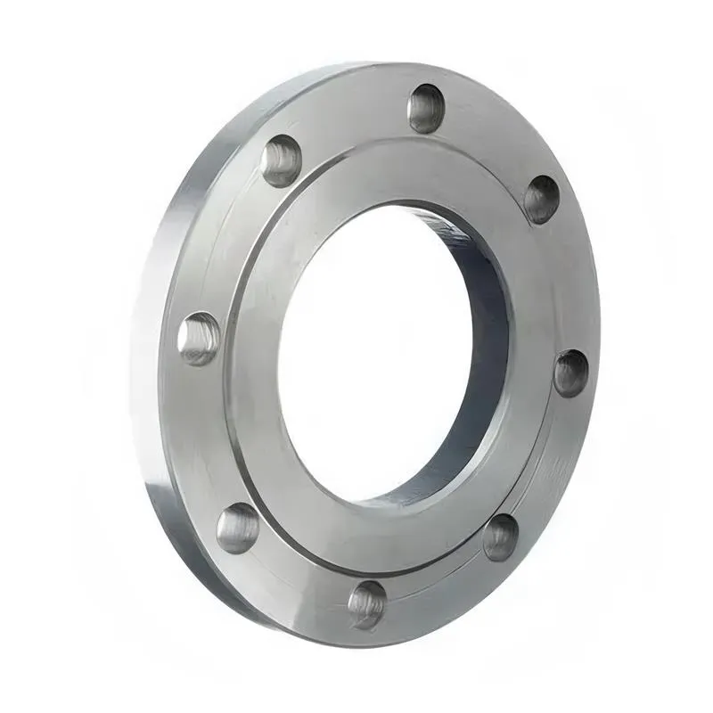
A flange—also referred to as a flange plate or rim—is a component used to connect shafts to one another, or, more commonly, to join the ends of pipes. Flanges are also utilized at the inlet and outlet ports of equipment to facilitate connections between two devices—for instance, the flange on a speed reducer. A "flange connection" or "flanged joint" refers to a detachable joint assembly comprising three interconnected elements—a flange, a gasket, and bolts—that together form a sealed structural unit. In the context of piping systems, a "pipe flange" specifically denotes a flange used for plumbing within the installation; when applied to equipment, it refers to the inlet or outlet flange of that specific device. Flanges feature a series of holes through which bolts are inserted to securely fasten the two flanges together, while a gasket placed between the flanges ensures a leak-proof seal. Flanges are broadly categorized into three types: threaded (screw-in) flanges, welded flanges, and clamp-type flanges. Flanges are invariably used in pairs; threaded flanges are suitable for low-pressure piping applications, whereas welded flanges are required for systems operating at pressures exceeding 4 kilograms per square centimeter. A sealing gasket is inserted between the two flange plates, which are then firmly secured using bolts. The thickness of a flange—as well as the specifications of the bolts used to fasten it—vary depending on the specific pressure rating required for the application. When connecting equipment such as water pumps or valves to piping systems, the corresponding connection points on these devices are often manufactured in the shape of a matching flange; this method of attachment is also referred to as a "flange connection." Generally, any connecting component that utilizes bolts to join and seal the perimeters of two flat surfaces—such as the joints in ventilation ducts—is termed a "flange"; such components may collectively be classified as "flange-type parts." However, since such a connection often constitutes merely a *portion* of a larger device—for instance, the interface between a flange and a water pump—it would be inappropriate to classify the entire water pump itself as a "flange-type part." Conversely, smaller components—such as valves—that feature such flanged interfaces may indeed be appropriately categorized as "flange-type parts."
-:-
For detailed product information, please contact sales.
-:
AISI 5147 Low Alloy Steel Flange, Annealed and Cold Drawn Bar Product Information
-:-
For detailed product information, please contact sales.
-:
AISI 5147 Low Alloy Steel Flange, Annealed and Cold Drawn Bar Synonyms
-:-
For detailed product information, please contact sales.
-:
AISI 5147 Low Alloy Steel, Annealed and Cold Drawn Bar Product Information
-:-
For detailed product information, please contact sales.
-:
# **AISI 5147 Low Alloy Steel, Annealed and Cold Drawn Bar - Technical Data Sheet**
## **1. Product Overview**
**AISI 5147 Annealed and Cold Drawn Bar** is a medium-high carbon chromium alloy steel supplied in a **precise, ready-to-machine condition** that combines the inherent strength characteristics of the 5147 chemistry with the dimensional accuracy and surface quality achieved through cold drawing. This product form is specifically engineered for applications requiring **excellent machinability, tight dimensional tolerances, and superior surface finish** before final heat treatment or use in the as-drawn condition.
The cold drawing process after annealing imparts several key advantages: improved surface finish (typically 32-125 μin Ra), enhanced dimensional accuracy (±0.001-0.003 in/in), increased yield strength through strain hardening, and superior straightness. This makes it particularly suitable for high-volume production of precision components that undergo minimal additional machining before use or heat treatment.
---
## **2. Chemical Composition (SAE J404/J412)**
| Element | Composition Range (%) | Metallurgical Function |
|---------|----------------------|------------------------|
| **Carbon (C)** | 0.45 - 0.50 | Provides high strength potential; balanced for good hardenability and toughness |
| **Manganese (Mn)** | 0.70 - 0.95 | Enhances hardenability and strength; contributes to cold work response |
| **Phosphorus (P)** | ≤ 0.035 | Residual impurity; minimized for improved ductility |
| **Sulfur (S)** | ≤ 0.040 | Typically controlled at lower levels for cold drawing compatibility |
| **Silicon (Si)** | 0.15 - 0.35 | Deoxidizer; provides solid solution strengthening |
| **Chromium (Cr)** | 0.85 - 1.15 | Primary alloying element; improves hardenability and wear resistance |
| **Iron (Fe)** | Balance | Base metal |
**Material Designations:**
- **SAE/AISI:** 5147
- **UNS:** G51470
- **Condition:** Annealed and Cold Drawn (A&CD)
- **Product Form:** Round bars, hex bars, square bars, special shapes
- **Surface Finish:** Cold drawn finish (32-125 μin Ra typical)
---
## **3. Physical & Mechanical Properties**
### **As-Supplied (Annealed and Cold Drawn Condition):**
**Typical Mechanical Properties:**
- **Hardness:** 201-255 HB (95-105 HRB)
- **Tensile Strength:** 690-930 MPa (100-135 ksi)
- **Yield Strength (0.2% offset):** 515-760 MPa (75-110 ksi) - *Enhanced by cold work*
- **Elongation (in 2"):** 12-18%
- **Reduction of Area:** 35-45%
- **Modulus of Elasticity:** 205 GPa (29,700 ksi)
- **Shear Modulus:** 80 GPa (11,600 ksi)
**Cold Drawn Characteristics:**
- **Surface Finish:** 0.8-3.2 μm Ra (32-125 μin Ra)
- **Dimensional Tolerance:** Typically ASTM A108 Table 7 (Commercial) or Table 8 (Precision)
- **Straightness:** 0.060 in/ft maximum (commercial), 0.030 in/ft (precision)
- **Decarburization:** ≤0.003 in total depth per side (controlled during processing)
- **Out-of-Roundness:** ≤0.001-0.003 in depending on diameter
**Comparison with Hot-Rolled Condition:**
| Property | Cold Drawn 5147 | Hot-Rolled 5147 | Improvement |
|----------|-----------------|-----------------|-------------|
| **Surface Finish** | 32-125 μin Ra | 250-500 μin Ra | 4-8× better |
| **Dimensional Tolerance** | ±0.001-0.003 in/in | ±0.010-0.020 in/in | 5-10× better |
| **Yield Strength** | 75-110 ksi | 55-75 ksi | 30-50% higher |
| **Straightness** | 0.030-0.060 in/ft | 0.100-0.250 in/ft | 3-5× better |
### **Physical Properties:**
- **Density:** 7.85 g/cm³ (0.284 lb/in³)
- **Melting Point:** 1480-1520°C (2695-2770°F)
- **Thermal Conductivity:** 43.0 W/m·K at 100°C
- **Coefficient of Thermal Expansion:** 12.1 μm/m·°C (20-100°C)
- **Specific Heat:** 460 J/kg·K at 20°C
- **Electrical Resistivity:** 0.24 μΩ·m at 20°C
### **Potential After Heat Treatment:**
*If subsequently heat treated (not typical for cold drawn products):*
- **Hardening Temperature:** 815-845°C (1500-1550°F)
- **Quenching:** Oil
- **Tempering Range:** 150-650°C (300-1200°F)
- **Achievable Hardness:** 50-58 HRC (as-quenched), 25-55 HRC (tempered)
---
## **4. Manufacturing Process & Characteristics**
### **Production Process Sequence:**
1. **Hot Rolling:** Initial breakdown to rough size
2. **Annealing:** Full anneal at 790-820°C to produce soft, machinable structure
3. **Pickling:** Acid cleaning to remove scale
4. **Cold Drawing:** Single or multiple passes through tungsten carbide dies
5. **Stress Relieving (Optional):** 315-400°C to relieve drawing stresses
6. **Straightening & Cutting:** To final length requirements
### **Cold Drawing Process Parameters:**
- **Reduction per Pass:** 10-25% area reduction typical
- **Die Material:** Tungsten carbide with 8-12° approach angle
- **Lubrication:** Phosphate coating with soap or oil-based lubricant
- **Drawing Speed:** 20-60 ft/min depending on size and reduction
- **Surface Preparation:** Phosphating for lubricant retention
### **Machinability in Cold Drawn Condition:**
- **Machinability Rating:** 45-50% (relative to 1212 steel = 100%)
- **Recommended Cutting Speed:** 40-60 SFM with HSS, 150-250 SFM with carbide
- **Feed Rate:** 0.005-0.015 in/rev for finishing, 0.010-0.030 in/rev for roughing
- **Tool Material:** Carbide grades C2-C5 or premium cobalt HSS
- **Chip Formation:** Continuous chips; chip breakers recommended
- **Coolant:** Water-soluble emulsion or neat oil for improved finish
- **Advantage over Annealed-only:** Better chip control, improved surface finish from machining
### **Formability Considerations:**
- **Cold Bending:** Limited due to work hardening; minimum bend radius ≈ 2× thickness
- **Cold Heading:** Possible with proper annealing sequence and reduction control
- **Thread Rolling:** Excellent compatibility; cold worked surface resists galling
- **Knurling:** Produces clean, sharp patterns due to cold worked surface
---
## **5. Product Applications**
### **Precision Shafting & Axles:**
- **Machine tool spindles** requiring minimal runout
- **Precision shafts** for pumps, compressors, and gearboxes
- **Axle shafts** for light vehicles in as-drawn condition
- **Linear motion components** requiring tight diameter control
- **Hydraulic piston rods** for smooth operation
### **Fastener & Component Manufacturing:**
- **High-strength fastener blanks** (bolts, studs, screws)
- **Precision pins** and dowels requiring consistent dimensions
- **Bearing races** and roller components
- **Valve stems** and hydraulic components
- **Specialty component stock** for CNC machining
### **Automotive & Transportation:**
- **Steering components** (tie rods, ball studs) in as-drawn or lightly machined condition
- **Suspension pins** and bushings
- **Drivetrain components** requiring precise dimensions
- **Brake system components** (caliper pins, guide pins)
### **Industrial Equipment:**
- **Textile machinery components** requiring smooth surfaces
- **Printing press rolls** and cylinders
- **Food processing equipment** shafts requiring cleanability
- **Material handling components** with wear surfaces
### **Special Applications:**
- **Medical device components** requiring precision and cleanliness
- **Aerospace components** with tight dimensional requirements
- **Optical equipment parts** requiring minimal machining
- **Instrumentation components** with critical dimensions
### **Typical Diameter Ranges:**
| Application | Typical Diameter Range | Tolerance Class | Surface Finish Requirement |
|-------------|------------------------|-----------------|---------------------------|
| Precision shafts | 0.250-4.000 in | ±0.001 in | 32-63 μin Ra |
| Fastener blanks | 0.125-2.000 in | ±0.002 in | 63-125 μin Ra |
| General machining | 0.500-6.000 in | ±0.003 in | 125-250 μin Ra |
| Special components | Custom sizes | As specified | As specified |
---
## **6. International Standards & Equivalents**
### **Primary Standards:**
| Standard | Designation | Specification Document |
|----------|-------------|------------------------|
| **SAE/AISI** | **5147** | SAE J404, J412 |
| **UNS** | **G51470** | Unified Numbering System |
| **ASTM** | **A108** | Standard for Steel Bars, Carbon, Cold-Finished |
| **AMS** | **AMS 2301** | Cleanliness requirements (special quality) |
### **Global Equivalent Grades:**
| Country/Region | Standard | Equivalent Grade | Notes |
|----------------|----------|-----------------|-------|
| **International (ISO)** | ISO 683-11 | **47Cr4** | Type 1.7043 |
| **Europe (EN)** | EN 10083-3 | **47Cr4** | Designation 1.7043 |
| **Germany** | DIN 17200 | **47Cr4** | Direct equivalent |
| **Japan** | JIS G4105 | **SCr445** | Very similar composition |
| **China** | GB/T 3077 | **45Cr** (45铬) | Close equivalent |
| **France** | NF A35-552 | **45C4** | French standard |
### **Cold Drawn Bar Specifications:**
- **ASTM A108:** Standard Specification for Steel Bars, Carbon, Cold-Finished
- **SAE J1397:** Steel Bars, Alloy, Hot-Wrought and Cold-Finished
- **ISO 286-2:** ISO system of limits and fits - Part 2
- **DIN EN 10278:** Bright steel products - Dimensions and tolerances
### **Tolerance Classes Available:**
| Tolerance Class | Diameter Range | Typical Application |
|-----------------|----------------|-------------------|
| **Commercial (ASTM A108 Table 7)** | All sizes | General machining |
| **Precision (ASTM A108 Table 8)** | Up to 3 in | Precision components |
| **Special Tolerances** | As specified | Critical applications |
| **Honing Allowance** | Custom | For subsequent honing |
---
## **7. Quality Control & Inspection**
### **Standard Testing Requirements:**
- **Chemical Analysis:** Per heat/lot (ASTM A751)
- **Hardness Testing:** Brinell or Rockwell B scale (ASTM E10/E18)
- **Tensile Testing:** Per lot (ASTM A370)
- **Surface Inspection:** Visual and dimensional checks
- **Straightness Verification:** Roll test or straight edge
### **Dimensional Tolerances (Typical):**
| Diameter (inches) | Commercial Tolerance (±) | Precision Tolerance (±) |
|-------------------|-------------------------|------------------------|
| 0.125 - 0.500 | 0.002 | 0.001 |
| 0.501 - 1.000 | 0.003 | 0.0015 |
| 1.001 - 2.000 | 0.004 | 0.002 |
| 2.001 - 3.000 | 0.005 | 0.0025 |
| 3.001 - 4.000 | 0.006 | 0.003 |
### **Surface Quality Requirements:**
- **Freedom from Defects:** No seams, laps, slivers, or excessive drawing marks
- **Decarburization Control:** ≤0.003 in total depth per side
- **Surface Roughness:** Typically 32-125 μin Ra, measurable by profilometer
- **Visual Standards:** Compared to established visual comparators
### **Special Testing Available:**
- **Ultrasonic Testing:** For internal quality assessment
- **Magnetic Particle Inspection:** For surface defect detection
- **Microcleanliness:** Per ASTM E45 if specified
- **Grain Size:** ASTM E112 (typically 5-7 for annealed condition)
### **Certification:**
- **Mill Test Certificate:** 2.2 or 3.1 per EN 10204
- **Material Traceability:** Heat/lot identification maintained
- **Process Certification:** Cold drawing process parameters documented
---
## **8. Advantages & Limitations**
### **Advantages of Annealed & Cold Drawn 5147:**
**Manufacturing Advantages:**
✅ **Reduced machining time** due to improved surface finish
✅ **Minimal material waste** from precise dimensions
✅ **Improved tool life** from consistent hardness and structure
✅ **Better chip control** during machining
✅ **Reduced secondary operations** (less grinding/polishing required)
**Performance Advantages:**
✅ **Higher yield strength** than hot-rolled material
✅ **Improved fatigue properties** from better surface finish
✅ **Enhanced wear resistance** in as-drawn condition
✅ **Superior dimensional stability** for precision assemblies
✅ **Better surface for plating/coating** adhesion
**Economic Advantages:**
✅ **Lower total cost** for high-volume precision parts
✅ **Reduced inspection time** due to consistent quality
✅ **Faster production cycles** with less setup time
✅ **Minimal scrap** from dimensional variations
### **Limitations & Considerations:**
⚠️ **Size limitations** (typically ≤6 in diameter for cold drawing)
⚠️ **Residual stresses** from cold work may affect stability
⚠️ **Limited formability** in cold worked condition
⚠️ **Potential for directional properties** (anisotropy)
⚠️ **Higher initial cost** compared to hot-rolled material
⚠️ **Stress relief may be required** for critical applications
⚠️ **Not suitable for welding** in cold worked condition
### **Economic Justification:**
| Cost Factor | Cold Drawn vs. Hot Rolled | Net Impact |
|-------------|---------------------------|------------|
| Material Cost | +20-40% higher | Negative |
| Machining Time | -30-50% less | Positive |
| Tooling Cost | -20-30% less | Positive |
| Scrap Rate | -50-70% less | Positive |
| Inspection Time | -40-60% less | Positive |
| **Total Cost** | **Often 10-25% lower** | **Positive** |
---
## **9. Design & Engineering Considerations**
### **Optimal Application Parameters:**
- **Diameter Range:** 0.125-6.000 inches optimal
- **Length:** Standard lengths 12-20 ft; cut pieces available
- **Straightness Requirements:** Up to 0.030 in/ft achievable
- **Surface Finish Needs:** Applications requiring 32-125 μin Ra
- **Tolerance Requirements:** Applications needing ±0.001-0.005 in diameter control
### **Stress Considerations:**
- **Residual Stress Pattern:** Surface compressive, core tensile
- **Stress Relief Recommendation:** For parts with asymmetric machining or tight tolerance requirements
- **Stress Relief Parameters:** 315-400°C for 1-2 hours, slow cool
- **Effect on Dimensions:** Minimal growth (0.0005-0.001 in/in typical)
### **Machining Recommendations:**
- **Turning:** Light finishing cuts (0.010-0.030 in) for best results
- **Grinding:** May be minimal or unnecessary due to surface finish
- **Drilling/Tapping:** Use sharp tools with adequate lubrication
- **Threading:** Produces clean, strong threads due to cold worked structure
- **Surface Treatments:** Excellent base for plating, painting, or other coatings
### **Assembly Considerations:**
- **Press Fits:** Cold worked surface provides good bearing strength
- **Slip Fits:** Consistent diameter enables predictable clearance
- **Threaded Assemblies:** Reduced galling compared to softer materials
- **Bearing Surfaces:** Smooth finish reduces break-in time
---
## **10. Processing & Heat Treatment Options**
### **Subsequent Heat Treatment Options:**
**Stress Relieving (Recommended for Precision Parts):**
- **Temperature:** 315-400°C (600-750°F)
- **Time:** 1-2 hours per inch of thickness
- **Atmosphere:** Air or protective to prevent oxidation
- **Result:** Reduced residual stresses, minimal hardness change
**Through-Hardening (If Required):**
- **Normalize First:** 870-900°C to relieve cold work effects
- **Austenitize:** 815-845°C (1500-1550°F)
- **Quench:** Oil for sections ≤2 in, water for larger (with caution)
- **Temper:** Based on required hardness
- **Note:** Cold worked structure will be eliminated by full hardening
**Surface Hardening Options:**
- **Induction Hardening:** Effective for selective area hardening
- **Nitriding:** Compatible with cold worked core
- **Carburizing:** Generally not recommended due to high base carbon
### **Finishing Operations:**
- **Grinding:** For ultra-precise dimensions or special finishes
- **Honing:** For specific surface texture requirements
- **Polishing:** For mirror finishes or reduced friction
- **Coating:** Phosphate, black oxide, electroplating, or painting
### **Joining Considerations:**
- **Welding:** Not recommended in cold worked condition; anneal first if necessary
- **Brazing:** Acceptable with proper procedures
- **Adhesive Bonding:** Excellent due to clean, consistent surface
- **Mechanical Fastening:** Ideal due to consistent dimensions and strength
---
## **11. Storage, Handling & Packaging**
### **Packaging Standards:**
- **Bundling:** Strapped in secure bundles with protective caps
- **Protection:** Oiled or VCI (Vapor Corrosion Inhibitor) wrapped
- **Identification:** Tagged with heat number, size, and specification
- **Loading:** Properly supported to prevent bending during transport
### **Storage Recommendations:**
- **Environment:** Dry, indoor storage preferred
- **Handling:** Use non-marring equipment to protect surface finish
- **Shelf Life:** 12 months with proper protection; inspect after 6 months
- **Rust Prevention:** Maintain protective coating; re-oil if necessary
### **Quality Preservation:**
- **First-In-First-Out:** Implement FIFO system
- **Condition Monitoring:** Regular inspection for rust or damage
- **Revalidation:** Test mechanical properties if stored >12 months
- **Re-work:** Light polishing or cleaning if surface deteriorates
---
**Technical Note:** AISI 5147 in annealed and cold drawn condition represents an optimized material form for precision manufacturing. The cold drawing process transforms the inherent properties of 5147 chemistry into a product with superior dimensional characteristics and surface quality, effectively moving value-added processing upstream in the supply chain. This enables manufacturers to reduce their in-house processing costs while improving part quality and consistency.
**Revision:** 1.1
**Date:** October 2023
**Disclaimer:** This technical data is for informational purposes. Actual properties may vary based on specific processing parameters, diameter, and reduction ratios. Cold drawn products exhibit directional properties; design accordingly. Always consult with material suppliers for application-specific recommendations and conduct appropriate testing for critical applications.
-:-
For detailed product information, please contact sales.
-:
AISI 5147 Low Alloy Steel, Annealed and Cold Drawn Bar Specification
Dimensions
Size:
Diameter 20-1000 mm Length <4120 mm
Size:We can customized as required
Standard:
Per your request or drawing
We can customized as required
Properties(Theoretical)
Chemical Composition
-:-
For detailed product information, please contact sales.
-:
AISI 5147 Low Alloy Steel, Annealed and Cold Drawn Bar Properties
-:-
For detailed product information, please contact sales.
-:
Applications of AISI 5147 Low Alloy Steel Flange, Annealed and Cold Drawn Bar
-:-
For detailed product information, please contact sales.
-:
Chemical Identifiers AISI 5147 Low Alloy Steel Flange, Annealed and Cold Drawn Bar
-:-
For detailed product information, please contact sales.
-:
Packing of AISI 5147 Low Alloy Steel Flange, Annealed and Cold Drawn Bar
-:-
For detailed product information, please contact sales.
-:
Standard Packing:
-:-
For detailed product information, please contact sales.
-:
Typical bulk packaging includes palletized plastic 5 gallon/25 kg. pails, fiber and Steel Flange drums to 1 ton super sacks in full container (FCL) or truck load (T/L) quantities. Research and sample quantities and hygroscopic, oxidizing or other air sensitive materials may be packaged under argon or vacuum. Solutions are packaged in polypropylene, plastic or glass jars up to palletized 591 gallon liquid totes Special package is available on request. E FORUs’ is carefully handled to minimize damage during storage and transportation and to preserve the quality of our products in their original condition


")
