1,We Manufacturing processes are primarily classified into four types:
1:Forging,
2:Casting,
3:Cutting,
4:Rolling.
2,We can manufacture in accordance with these standards.
Standards:
GB Series (Chinese Standards), JB Series (Machinery Standards), HG Series (Chemical Industry Standards), ASME B16.5 (American Standards), BS4504 (British Standards), DIN (German Standards), and JIS (Japanese Standards).
Internationally, there are two primary systems of pipe flange standards: the European system, represented by the German DIN standards (including those of the former Soviet Union), and the American system, represented by the US ANSI pipe flange standards. Other common standards include: the Chinese Ministry of Machinery Industry standards (JB series), the Ministry of Chemical Industry standards (HG series), the Chinese National Standard *GB/T 9112–9124-2010 Steel Pipe Flanges*, as well as US standards (ASME B16.5), British standards (BS4504), German standards (DIN), Japanese standards (JIS), and marine standards (CBM), among others.
The nominal pressure ratings for the PN series are designated by "PN" and comprise the following nine levels: PN2.5, PN6, PN10, PN16, PN25, PN40, PN63, PN100, and PN160.
The nominal pressure ratings for the Class series are designated by "Class" and comprise the following six levels: Class150, Class300, Class600, Class900, Class1500, and Class2500.
Flange Classification
1. **According to Chemical Industry Standards:** Flanges are classified as follows:
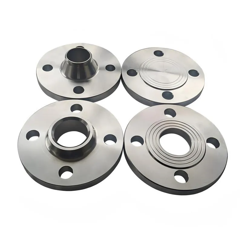
Plate Flat Welding Flange (PL), Necked Flat Welding Flange (SO), Necked Butt Welding Flange (WN), Integral Flange (IF), Socket Welding Flange (SW), Threaded Flange (Th), Butt Welding Ring Loose Flange (PJ/SE), Blind Flange (BL), Flat Welding Ring Loose Flange (PJ/PJ), and Lined Blind Flange (BL(s)).
2. **According to Petrochemical (SH) Industry Standards:** Flanges are classified as follows:
Threaded Flange (PL), Butt Welding Flange (WN), Flat Welding Flange (SO), Socket Welding Flange (SW), Loose Flange (LJ), and Blind Flange (no specific designation).
3. **According to Machinery (JB) Industry Standards:** Flanges are classified as follows:
Integral Flange, Butt Welding Flange, Plate Flat Welding Flange, Butt Welding Ring Plate Loose Flange, Flat Welding Ring Plate Loose Flange, Lap Joint Ring Plate Loose Flange, and Blind Flange.
4. **According to Connection Method/Type:** Flanges are classified as follows:
Plate Flat Welding Flange, Necked Flat Welding Flange, Necked Butt Welding Flange, Socket Welding Flange, Threaded Flange, Blind Flange, Necked Butt Welding Ring Loose Flange, Flat Welding Ring Loose Flange, Ring-Type Joint (RTJ) Flange and Blind Flange, Large-Diameter Plate Flange, Large-Diameter High-Neck Flange, Figure-8 Blind Plate, Butt Welding Ring Loose Flange, etc.
5. **According to the Component Being Connected:** Flanges can be classified into Vessel Flanges and Pipe Flanges.
6. **According to Structural Type:** Flanges include Integral Flanges, Threaded Flanges, Flat Welding Flanges, Butt Welding Flanges, Lap Joint (Loose/Swivel) Flanges, and Blind Flanges.
A flange—also referred to as a flange plate or rim—is a component used to connect shafts to one another, or, more commonly, to join the ends of pipes. Flanges are also utilized at the inlet and outlet ports of equipment to facilitate connections between two devices—for instance, the flange on a speed reducer. A "flange connection" or "flanged joint" refers to a detachable joint assembly comprising three interconnected elements—a flange, a gasket, and bolts—that together form a sealed structural unit. In the context of piping systems, a "pipe flange" specifically denotes a flange used for plumbing within the installation; when applied to equipment, it refers to the inlet or outlet flange of that specific device. Flanges feature a series of holes through which bolts are inserted to securely fasten the two flanges together, while a gasket placed between the flanges ensures a leak-proof seal. Flanges are broadly categorized into three types: threaded (screw-in) flanges, welded flanges, and clamp-type flanges. Flanges are invariably used in pairs; threaded flanges are suitable for low-pressure piping applications, whereas welded flanges are required for systems operating at pressures exceeding 4 kilograms per square centimeter. A sealing gasket is inserted between the two flange plates, which are then firmly secured using bolts. The thickness of a flange—as well as the specifications of the bolts used to fasten it—vary depending on the specific pressure rating required for the application. When connecting equipment such as water pumps or valves to piping systems, the corresponding connection points on these devices are often manufactured in the shape of a matching flange; this method of attachment is also referred to as a "flange connection." Generally, any connecting component that utilizes bolts to join and seal the perimeters of two flat surfaces—such as the joints in ventilation ducts—is termed a "flange"; such components may collectively be classified as "flange-type parts." However, since such a connection often constitutes merely a *portion* of a larger device—for instance, the interface between a flange and a water pump—it would be inappropriate to classify the entire water pump itself as a "flange-type part." Conversely, smaller components—such as valves—that feature such flanged interfaces may indeed be appropriately categorized as "flange-type parts."
-:-
For detailed product information, please contact sales.
-:
ASTM A197 malleable Iron Flange casting Product Information
-:-
For detailed product information, please contact sales.
-:
ASTM A197 malleable Iron Flange casting Synonyms
-:-
For detailed product information, please contact sales.
-:
ASTM A197 malleable iron casting Product Information
-:-
For detailed product information, please contact sales.
-:
# ASTM A197 Malleable Iron Castings - Comprehensive Technical Overview
## 1. Product Definition & Overview
**ASTM A197** specifies the standard requirements for **cupola malleable iron castings**, a specialized type of ferritic malleable iron produced primarily in cupola furnaces. This material represents the traditional foundation of the malleable iron industry, characterized by its **exceptional ductility, superior machinability, and reliable performance** in applications requiring shock and impact resistance. Unlike modern electric furnace-produced malleable irons, A197 maintains specific chemical constraints that reflect its historical production methods while delivering consistent mechanical properties suitable for a wide range of industrial applications.
## 2. International Standards & Specifications
### Primary Governing Standard
- **ASTM A197/A197M**: *Standard Specification for Cupola Malleable Iron* (Latest Revision)
### Related & Referenced Standards
- **ASTM A47/A47M**: For ferritic malleable iron castings (performance-based companion standard)
- **ASTM A247**: Standard test method for evaluating graphite microstructure in cast iron
- **ASTM E8/E8M**: Standard test methods for tension testing of metallic materials
- **ASTM E10**: Standard test method for Brinell hardness of metallic materials
- **SAE J158**: Automotive malleable iron castings specifications
- **ISO 5922**: Internationally recognized standard for malleable cast irons
- **EN 1562**: European standard for malleable cast irons
### Grade Classifications
While ASTM A197 itself does not specify grade designations like ASTM A47, castings conforming to A197 typically align with traditional malleable iron grades including:
- Equivalent to **ASTM A47 32510** (32,500 psi tensile, 10% elongation)
- Equivalent to **ASTM A47 35018** (35,000 psi tensile, 18% elongation) when produced to higher performance levels
## 3. Chemical Composition Requirements
### Mandatory Chemical Limits (Weight %)
| Element | Maximum Percentage | Rationale & Impact |
|---------|-------------------|-------------------|
| **Carbon (C)** | No specific maximum | Typically 2.20-2.90% for proper graphitization |
| **Silicon (Si)** | **1.75% max** | Critical control element; promotes graphitization |
| **Manganese (Mn)** | **0.55% max** | Counteracts sulfur; enhances strength |
| **Phosphorus (P)** | **0.12% max** | Improves fluidity but reduces toughness |
| **Sulfur (S)** | **0.12% max** | Controlled impurity; affects brittleness |
| **Chromium (Cr)** | **0.08% max** | Strictly limited - inhibits graphitization |
| **Copper (Cu)** | **0.30% max** | Optional; sometimes added for corrosion resistance |
### Unique Compositional Aspects of Cupola-Produced Iron
1. **Higher Phosphorus Tolerance**: Traditional cupola practice allows slightly higher phosphorus levels compared to electric furnace malleable iron
2. **Silicon Control**: Maximum silicon limited to 1.75% to control graphitization rate during annealing
3. **Carbon Equivalent**: Typically ranges from 3.6-4.2% for proper foundry characteristics
4. **Trace Elements**: Natural trace elements from raw materials may be present in higher quantities than in electric furnace iron
## 4. Physical & Mechanical Properties
### Minimum Mechanical Requirements
| Property | Requirement | Typical Range | Test Standard |
|----------|------------|--------------|---------------|
| **Tensile Strength** | Not specified min. | 32,000-38,000 psi (220-262 MPa) | ASTM E8 |
| **Yield Strength** | Not specified min. | 22,000-26,000 psi (152-179 MPa) | ASTM E8 |
| **Elongation** | Not specified min. | 10-18% in 2 inches | ASTM E8 |
| **Brinell Hardness** | Not specified | 110-156 HB | ASTM E10 |
*Note: Unlike ASTM A47, A197 does not specify minimum mechanical properties but requires castings to be "suitable for the service intended"*
### Comprehensive Property Profile
**Mechanical Characteristics:**
- **Tensile Strength**: 220-260 MPa (32,000-38,000 psi)
- **Yield Strength**: 150-180 MPa (22,000-26,000 psi)
- **Elongation**: 10-18% (typical)
- **Impact Resistance**: Excellent - Charpy values typically 12-20 J at room temperature
- **Fatigue Strength**: Moderate - approximately 40-50% of tensile strength
- **Modulus of Elasticity**: 170-180 GPa (24.6-26.1 × 10⁶ psi)
**Physical Properties:**
- **Density**: 7.25-7.35 g/cm³
- **Melting Range**: 1130-1200°C
- **Thermal Conductivity**: 42-48 W/m·K at 20°C
- **Coefficient of Thermal Expansion**: 10.8-11.2 × 10⁻⁶/°C (20-200°C)
- **Electrical Resistivity**: 0.32-0.38 μΩ·m
- **Damping Capacity**: Good - approximately 5-7 times better than steel
**Manufacturing Properties:**
- **Machinability**: Excellent - 85-95% relative to B1112 steel
- **Castability**: Very Good - fluidity index typically 35-45 inches
- **Surface Finish**: As-cast finish of 250-500 μ-in (6.3-12.7 μm Ra)
- **Dimensional Stability**: Good during annealing
## 5. Microstructural Characteristics
### As-Cast Structure
- **Primary Phase**: White iron (cementite + pearlite)
- **Carbide Network**: Continuous carbide matrix
- **No Graphite**: Absolutely no graphite in as-cast condition
### Annealed Structure (After Malleablization)
- **Matrix**: Predominantly ferritic (>90% ferrite)
- **Carbon Form**: Temper carbon aggregates (rosettes or nodules)
- **Carbide Content**: Less than 1% residual carbides
- **Grain Size**: ASTM 4-7 (typically)
- **Carbon Aggregate Distribution**: Uniformly dispersed throughout matrix
### Heat Treatment Process
The malleablization process for A197 iron typically involves:
1. **Stage 1**: 900-950°C for 15-40 hours (graphitization of cementite)
2. **Stage 2**: 700-730°C for 15-30 hours (decomposition of pearlite to ferrite)
3. **Total Cycle**: 30-70 hours depending on section size and chemistry
4. **Cooling**: Controlled furnace cooling to prevent embrittlement
## 6. Product Applications
### Traditional & Historical Applications
- **Pipe Fittings**: Gas and water pipe fittings (elbows, tees, couplings)
- **Plumbing Hardware**: Faucet bodies, valve components, pipe connectors
- **Agricultural Equipment**: Implement parts, tractor components
- **Railroad Equipment**: Coupler parts, brake components
- **Early Automotive**: Model T Ford components, early transmission parts
### Modern Industrial Applications
- **Electrical Fittings**: Conduit bodies, junction boxes, cable guards
- **Hardware Components**: Brackets, hinges, fasteners
- **Material Handling**: Chain links, conveyor parts, hoist components
- **Construction Hardware**: Scaffolding fittings, beam clamps, anchor plates
- **Valve Components**: Low-pressure valve bodies, bonnets, stems
### Specialized Uses
1. **Threaded Components**: Excellent for threaded parts due to good ductility
2. **Impact-Resistant Parts**: Applications requiring shock absorption
3. **Complex Geometries**: Thin-walled, intricate castings
4. **Pressure-Containing Parts**: Low-pressure fluid handling applications
## 7. Manufacturing Process Specifics
### Cupola Melting Characteristics
- **Fuel**: Typically coke with forced air blast
- **Charge Materials**: Pig iron, steel scrap, returns, and alloys
- **Temperature Control**: Less precise than electric furnaces
- **Chemistry Control**: More variable but historically proven
- **Atmosphere**: Oxidizing conditions affecting element recovery
### Foundry Advantages
1. **Lower Capital Cost**: Cupola installation costs less than electric furnaces
2. **High Melt Rates**: Continuous melting capability
3. **Traditional Skill Base**: Established expertise in many regions
4. **Raw Material Flexibility**: Can use various scrap mixtures
### Quality Control Considerations
- **More Frequent Chemistry Checks**: Due to process variability
- **Temperature Monitoring**: Critical for consistent results
- **Charge Control**: Careful selection and proportioning of charge materials
- **Slag Management**: Important for element recovery and impurity control
## 8. Advantages and Limitations
### Key Advantages
1. **Proven Reliability**: Over 150 years of successful application history
2. **Excellent Machinability**: Among the most machinable ferrous materials
3. **Good Ductility**: Withstands bending and deformation
4. **Impact Resistance**: Absorbs shock without fracturing
5. **Pressure Tightness**: Reliable for fluid containment
6. **Cost-Effectiveness**: Economical for high-volume production
7. **Surface Finish**: Good as-cast appearance
### Limitations and Considerations
1. **Lower Strength**: Compared to modern ductile irons and steels
2. **Lengthy Heat Treatment**: Extended annealing cycles (30-70 hours)
3. **Section Sensitivity**: Properties vary with casting thickness
4. **Process Control**: More challenging than electric furnace processes
5. **Environmental Factors**: Cupola emissions require modern controls
6. **Temperature Limitations**: Not suitable for high-temperature service (>425°C)
## 9. Comparative Analysis
### vs. Electric Furnace Malleable Iron (ASTM A47)
- **Process**: Cupola vs. electric furnace melting
- **Control**: Less precise chemistry control vs. tighter control
- **Tradition**: Historical method vs. modern production
- **Applications**: Often similar end-use applications
### vs. Ductile Iron (ASTM A536)
- **Strength**: Lower tensile and yield strength
- **Ductility**: Comparable or better elongation
- **Production**: Longer heat treatment vs. as-cast properties
- **Cost**: Often more economical for certain applications
### vs. Gray Iron (ASTM A48)
- **Ductility**: Dramatically superior ductility and toughness
- **Machinability**: Better machining characteristics
- **Strength**: Similar or slightly higher tensile strength
- **Impact Resistance**: Significantly better impact properties
## 10. Quality Assurance and Testing
### Standard Quality Practices
1. **Chemical Analysis**: For each heat or lot
2. **Mechanical Testing**: Tensile tests from separately cast keel blocks
3. **Microstructural Examination**: Verification of proper graphitization
4. **Pressure Testing**: For fluid-handling components
5. **Dimensional Inspection**: Per drawing requirements
### Special Requirements
- **Graphitization Verification**: Essential to ensure complete annealing
- **Hardness Testing**: Often used for production control
- **Surface Inspection**: Visual examination for defects
- **Proof Loading**: For critical load-bearing components
## 11. Environmental and Sustainability Aspects
### Energy Consumption
- **Melting Energy**: Cupola efficiency typically 50-65%
- **Annealing Energy**: Significant due to long cycle times
- **Total Energy**: Higher than some competing materials
### Environmental Considerations
1. **Emissions Control**: Modern cupolas require baghouses and scrubbers
2. **Material Recycling**: High percentage of recycled content (often 60-80%)
3. **Waste Minimization**: Foundry sand recycling and reuse
4. **Long Service Life**: Durable products reduce replacement frequency
### Sustainability Factors
- **Recyclability**: 100% recyclable without property degradation
- **Life Cycle**: Long service life in many applications
- **Local Production**: Often produced regionally, reducing transportation
- **Proven Durability**: Extended service reduces resource consumption
## 12. Modern Relevance and Future Outlook
### Current Market Position
- **Niche Applications**: Specific markets where traditional properties are valued
- **Regional Production**: Concentrated in areas with historical expertise
- **Specialized Products**: Components benefiting from unique characteristics
### Technical Developments
1. **Process Improvements**: Modern cupola control systems
2. **Environmental Upgrades**: Emission control technologies
3. **Quality Enhancements**: Statistical process control implementation
4. **Alloy Modifications**: Minor additions to improve specific properties
### Future Prospects
- **Heritage Applications**: Continued use in traditional products
- **Specialized Markets**: Where specific property combinations are needed
- **Modern Adaptations**: Integration with new manufacturing technologies
- **Sustainability Focus**: Improved energy efficiency and recycling
## 13. Conclusion
**ASTM A197 Cupola Malleable Iron** represents an important chapter in the history of ferrous metallurgy, embodying traditional manufacturing methods that continue to deliver valuable engineering properties. While largely superseded by electric furnace malleable iron (ASTM A47) and ductile iron in many applications, A197 maintains relevance in specific markets where its unique combination of exceptional machinability, good ductility, and proven reliability align with application requirements. The material's historical significance, established performance record, and continued production in certain regions ensure its place in the materials engineering landscape, particularly for applications where traditional characteristics and cost-effectiveness are prioritized over maximum strength or modern production methods.
The continued specification of ASTM A197 reflects both respect for traditional engineering practices and recognition that different production methods can yield materials with distinct advantages for particular applications. As manufacturing evolves, the principles embodied in A197—controlled composition, thorough heat treatment, and consistent quality—remain relevant to materials engineering across all metalcasting sectors.
-:-
For detailed product information, please contact sales.
-:
ASTM A197 malleable iron casting Specification
Dimensions
Size:
Diameter 20-1000 mm Length <6575 mm
Size:We can customized as required
Standard:
Per your request or drawing
We can customized as required
Properties(Theoretical)
Chemical Composition
-:-
For detailed product information, please contact sales.
-:
ASTM A197 malleable iron casting Properties
-:-
For detailed product information, please contact sales.
-:
Applications of ASTM A197 malleable Iron Flange casting
-:-
For detailed product information, please contact sales.
-:
Chemical Identifiers ASTM A197 malleable Iron Flange casting
-:-
For detailed product information, please contact sales.
-:
Packing of ASTM A197 malleable Iron Flange casting
-:-
For detailed product information, please contact sales.
-:
Standard Packing:
-:-
For detailed product information, please contact sales.
-:
Typical bulk packaging includes palletized plastic 5 gallon/25 kg. pails, fiber and Steel Flange drums to 1 ton super sacks in full container (FCL) or truck load (T/L) quantities. Research and sample quantities and hygroscopic, oxidizing or other air sensitive materials may be packaged under argon or vacuum. Solutions are packaged in polypropylene, plastic or glass jars up to palletized 3046 gallon liquid totes Special package is available on request. E FORUs’ is carefully handled to minimize damage during storage and transportation and to preserve the quality of our products in their original condition