1,We Manufacturing processes are primarily classified into four types:
1:Forging,
2:Casting,
3:Cutting,
4:Rolling.
2,We can manufacture in accordance with these standards.
Standards:
GB Series (Chinese Standards), JB Series (Machinery Standards), HG Series (Chemical Industry Standards), ASME B16.5 (American Standards), BS4504 (British Standards), DIN (German Standards), and JIS (Japanese Standards).
Internationally, there are two primary systems of pipe flange standards: the European system, represented by the German DIN standards (including those of the former Soviet Union), and the American system, represented by the US ANSI pipe flange standards. Other common standards include: the Chinese Ministry of Machinery Industry standards (JB series), the Ministry of Chemical Industry standards (HG series), the Chinese National Standard *GB/T 9112–9124-2010 Steel Pipe Flanges*, as well as US standards (ASME B16.5), British standards (BS4504), German standards (DIN), Japanese standards (JIS), and marine standards (CBM), among others.
The nominal pressure ratings for the PN series are designated by "PN" and comprise the following nine levels: PN2.5, PN6, PN10, PN16, PN25, PN40, PN63, PN100, and PN160.
The nominal pressure ratings for the Class series are designated by "Class" and comprise the following six levels: Class150, Class300, Class600, Class900, Class1500, and Class2500.
Flange Classification
1. **According to Chemical Industry Standards:** Flanges are classified as follows:
Plate Flat Welding Flange (PL), Necked Flat Welding Flange (SO), Necked Butt Welding Flange (WN), Integral Flange (IF), Socket Welding Flange (SW), Threaded Flange (Th), Butt Welding Ring Loose Flange (PJ/SE), Blind Flange (BL), Flat Welding Ring Loose Flange (PJ/PJ), and Lined Blind Flange (BL(s)).
2. **According to Petrochemical (SH) Industry Standards:** Flanges are classified as follows:
Threaded Flange (PL), Butt Welding Flange (WN), Flat Welding Flange (SO), Socket Welding Flange (SW), Loose Flange (LJ), and Blind Flange (no specific designation).
3. **According to Machinery (JB) Industry Standards:** Flanges are classified as follows:
Integral Flange, Butt Welding Flange, Plate Flat Welding Flange, Butt Welding Ring Plate Loose Flange, Flat Welding Ring Plate Loose Flange, Lap Joint Ring Plate Loose Flange, and Blind Flange.
4. **According to Connection Method/Type:** Flanges are classified as follows:
Plate Flat Welding Flange, Necked Flat Welding Flange, Necked Butt Welding Flange, Socket Welding Flange, Threaded Flange, Blind Flange, Necked Butt Welding Ring Loose Flange, Flat Welding Ring Loose Flange, Ring-Type Joint (RTJ) Flange and Blind Flange, Large-Diameter Plate Flange, Large-Diameter High-Neck Flange, Figure-8 Blind Plate, Butt Welding Ring Loose Flange, etc.
5. **According to the Component Being Connected:** Flanges can be classified into Vessel Flanges and Pipe Flanges.
6. **According to Structural Type:** Flanges include Integral Flanges, Threaded Flanges, Flat Welding Flanges, Butt Welding Flanges, Lap Joint (Loose/Swivel) Flanges, and Blind Flanges.
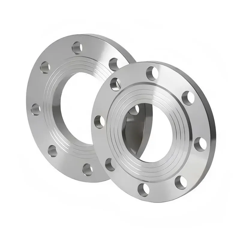
A flange—also referred to as a flange plate or rim—is a component used to connect shafts to one another, or, more commonly, to join the ends of pipes. Flanges are also utilized at the inlet and outlet ports of equipment to facilitate connections between two devices—for instance, the flange on a speed reducer. A "flange connection" or "flanged joint" refers to a detachable joint assembly comprising three interconnected elements—a flange, a gasket, and bolts—that together form a sealed structural unit. In the context of piping systems, a "pipe flange" specifically denotes a flange used for plumbing within the installation; when applied to equipment, it refers to the inlet or outlet flange of that specific device. Flanges feature a series of holes through which bolts are inserted to securely fasten the two flanges together, while a gasket placed between the flanges ensures a leak-proof seal. Flanges are broadly categorized into three types: threaded (screw-in) flanges, welded flanges, and clamp-type flanges. Flanges are invariably used in pairs; threaded flanges are suitable for low-pressure piping applications, whereas welded flanges are required for systems operating at pressures exceeding 4 kilograms per square centimeter. A sealing gasket is inserted between the two flange plates, which are then firmly secured using bolts. The thickness of a flange—as well as the specifications of the bolts used to fasten it—vary depending on the specific pressure rating required for the application. When connecting equipment such as water pumps or valves to piping systems, the corresponding connection points on these devices are often manufactured in the shape of a matching flange; this method of attachment is also referred to as a "flange connection." Generally, any connecting component that utilizes bolts to join and seal the perimeters of two flat surfaces—such as the joints in ventilation ducts—is termed a "flange"; such components may collectively be classified as "flange-type parts." However, since such a connection often constitutes merely a *portion* of a larger device—for instance, the interface between a flange and a water pump—it would be inappropriate to classify the entire water pump itself as a "flange-type part." Conversely, smaller components—such as valves—that feature such flanged interfaces may indeed be appropriately categorized as "flange-type parts."
-:-
For detailed product information, please contact sales.
-:
Ovako C55E EN10083-2:2006 (ref) Steel Flange, +S Product Information
-:-
For detailed product information, please contact sales.
-:
Ovako C55E EN10083-2:2006 (ref) Steel Flange, +S Synonyms
-:-
For detailed product information, please contact sales.
-:
Ovako C55E EN10083-2:2006 (ref) Steel, +S Product Information
-:-
For detailed product information, please contact sales.
-:
# **Product Introduction: Ovako C55E EN 10083-2:2006 (ref) Steel, +S Condition**
**Ovako C55E EN 10083-2:2006 (ref), +S** is a **high-carbon, non-alloy quality steel** supplied by Ovako in the **softened or spheroidize-annealed (+S) condition**. The designation signifies that the steel is produced in alignment with the European standard EN 10083-2 for the C55E grade, with the critical addition of the **"+S" delivery condition**, indicating it has undergone a specific thermal treatment to achieve an optimal microstructure for machining prior to final hardening.
The "+S" condition is a controlled spheroidizing or full annealing process that transforms the steel's hard cementite network into soft, globular carbides dispersed in a soft ferritic matrix. This results in the **lowest possible hardness and maximum ductility** for this chemistry, making it the ideal pre-machining state for complex components that will later be heat-treated to achieve high hardness and wear resistance.
---
## **1. Chemical Composition (Per EN 10083-2:2006 - Grade 1.1203/C55E)**
The composition adheres to the standard limits for the high-carbon C55E engineering steel grade.
| Element | Carbon (C) | Silicon (Si) | Manganese (Mn) | Phosphorus (P) | Sulfur (S) | Chromium (Cr)* |
| :--- | :--- | :--- | :--- | :--- | :--- | :--- |
| **EN 10083-2 Limits for C55E** | 0.52 - 0.60 | ≤ 0.40 | 0.60 - 0.90 | ≤ 0.035 | ≤ 0.035 | ≤ 0.40 |
| **Ovako Typical in +S Condition** | 0.54 - 0.58 | 0.15 - 0.30 | 0.65 - 0.85 | **≤ 0.025** | **≤ 0.020** | ≤ 0.25 |
| **Key Role** | **Primary hardness potential.** | Deoxidizer. | Hardenability agent. | **Low for post-hardening toughness.** | **Low for machinability & isotropy.** | Residual, aids hardenability. |
**Critical Features for the +S Condition:**
* **High Carbon Content (0.52-0.60%):** Defines the ultimate hardening potential but makes the material inherently difficult to machine in non-annealed states. The +S treatment is essential to overcome this.
* **"+S" (Softened/Spheroidized) Microstructure:** This is the defining process. The steel is heated and cooled very slowly to produce a microstructure of **soft, spherical cementite particles in a ferrite matrix**. This drastically reduces hardness and eliminates continuous hard carbide networks that would cause excessive tool wear.
* **Optimized for Machinability:** The +S condition is specified specifically to enable economical and precise machining (turning, milling, drilling, threading) before the component undergoes its final hardening quench, after which machining becomes extremely difficult or impossible.
---
## **2. Physical & Mechanical Properties (+S Condition)**
The properties in the +S condition are tailored for manufacturability, not for final performance.
| Property | **Guaranteed / Typical Values - +S Condition** | **Technical Significance** |
| :--- | :--- | :--- |
| **Hardness** | **≤ 200 HB** (Typically **165 - 190 HB**) | **Minimized for machining.** This is the key deliverable of the +S state. |
| **Tensile Strength (Rm)** | **580 - 700 MPa** | Low strength relative to the steel's potential. |
| **Yield Strength (Rp0.2)** | **≥ 320 MPa** | |
| **Elongation (A₅)** | **≥ 18%** | **High ductility,** allowing for some forming/cold adjustment after machining if needed. |
| **Microstructure** | **Spheroidized cementite in a ferritic matrix** (per ISO 945). | The optimal structure for tool life and surface finish. |
| **Machinability** | **Good (for a high-carbon steel).** The soft, homogeneous structure provides predictable tool wear, good chip control (though chips can be stringy), and allows for excellent surface finishes. Vastly superior to normalized or as-rolled C55. | **Primary reason for specifying +S.** |
| **Dimensional Stability** | Good. The annealing process relieves internal stresses from rolling. | Reduces risk of distortion during subsequent machining. |
**Note on Final Properties (After Customer Hardening):** After machining, the component must be heat treated (quenched and tempered) to achieve its service properties. Typical results:
* **Hardness after Q&T:** 55 - 62 HRC
* **Tensile Strength (Rm):** 1800 - 2200 MPa
* **Toughness:** Low (characteristic of high-carbon hardened steel).
---
## **3. Product Applications**
This material is specified for **complex, high-precision components** that require extensive machining and will later be hardened for wear resistance.
* **Precision Tools & Dies:** **Complex punches, forming dies, shear blades, and gauges** that require intricate machining before hardening.
* **Automotive & Aerospace Components:** **High-wear camshafts, fuel system parts, and actuator components** with tight tolerances.
* **Machine Tool Components:** **Lead screws, precision shafts, and spindle parts** requiring fine finishes before surface or through-hardening.
* **Hydraulic & Valve Parts:** **Complex valve bodies, pistons, and pump components** for high-pressure systems.
* **Gearing:** **Gear blanks** that are machined to final tooth geometry before case hardening or through-hardening.
---
## **4. International & Equivalent Standards**
The "+S" condition is a specific delivery requirement applied to a standard grade.
| Standard System | Equivalent Grade & Condition | **Relationship / Note** |
| :--- | :--- | :--- |
| **Ovako Specification** | **C55E EN 10083-2 (ref), +S** | The exact product: standard grade + soft condition. |
| **EN 10083-2** | **1.1203 (C55E)** + **Condition +A (Annealed)** | The "+A" condition in EN standards is equivalent to "+S" (Softened/Annealed). |
| **DIN** | **1.1203 (Ck55) + weichgeglüht** | German for "soft annealed". |
| **ASTM A29/A29M** | **Grade 1055, Annealed** | The U.S. equivalent grade and condition. |
| **JIS G4051** | **S55C, Annealed** | Japanese equivalent. |
| **GB/T 699** | **55# Steel, Annealed** | Chinese equivalent. |
**Key Distinction:** Specifying **"+S" (or "+A") is critical.** Ordering simply "C55E" will typically result in delivery in a **normalized (+N) or as-rolled (+AR) condition**, which is significantly harder (≥210 HB) and much more difficult to machine, leading to higher tool costs, longer cycle times, and potential quality issues. The +S condition is a value-added processing step.
---
## **5. Key Advantages & Considerations**
**Advantages:**
* **Superior Machinability:** Enables the economical production of complex parts from high-carbon steel, which would otherwise be prohibitively expensive or impossible to machine.
* **Excellent Surface Finish:** The uniform soft structure allows for the achievement of fine surface finishes during machining.
* **Reduced Tool Wear:** Extends tool life dramatically compared to machining higher-hardness conditions.
* **Good Dimensional Stability:** Stress-relieved structure minimizes movement during and after machining.
* **Allows Complex Geometries:** Makes it feasible to produce intricate features that could not be formed after hardening.
**Considerations:**
* **Additional Cost:** The spheroidizing annealing process adds to the base material cost.
* **Not a Final Use Condition:** The material is useless for its intended service application in the +S state; **customer hardening is mandatory**.
* **Softer than Typical "Annealed":** The +S condition is often softer than a standard "annealed" or "normalized" state, which must be considered in machining fixture design.
* **Stringy Chips:** Can produce long, stringy chips during machining, which may require specific chip-breaking tool geometries or handling.
---
**Disclaimer:** The **"+S" condition is specified for machining purposes only.** All design calculations must be based on the **final mechanical properties achieved after the customer's quenching and tempering process.** It is imperative to:
1. **Clearly specify "+S" or "Soft Annealed" in the purchase order.**
2. **Consult Ovako for the recommended hardening parameters (austenitizing temperature, quenching medium) for this specific grade and batch.**
3. **Validate the entire process** (machining + heat treatment) on sample parts to ensure dimensional stability and final properties meet requirements. The success of the final component depends entirely on the control of both the machining and the subsequent heat treatment.
-:-
For detailed product information, please contact sales.
-:
Ovako C55E EN10083-2:2006 (ref) Steel, +S Specification
Dimensions
Size:
Diameter 20-1000 mm Length <5092 mm
Size:We can customized as required
Standard:
Per your request or drawing
We can customized as required
Properties(Theoretical)
Chemical Composition
-:-
For detailed product information, please contact sales.
-:
Ovako C55E EN10083-2:2006 (ref) Steel, +S Properties
-:-
For detailed product information, please contact sales.
-:
Applications of Ovako C55E EN10083-2:2006 (ref) Steel Flange, +S
-:-
For detailed product information, please contact sales.
-:
Chemical Identifiers Ovako C55E EN10083-2:2006 (ref) Steel Flange, +S
-:-
For detailed product information, please contact sales.
-:
Packing of Ovako C55E EN10083-2:2006 (ref) Steel Flange, +S
-:-
For detailed product information, please contact sales.
-:
Standard Packing:
-:-
For detailed product information, please contact sales.
-:
Typical bulk packaging includes palletized plastic 5 gallon/25 kg. pails, fiber and Steel Flange drums to 1 ton super sacks in full container (FCL) or truck load (T/L) quantities. Research and sample quantities and hygroscopic, oxidizing or other air sensitive materials may be packaged under argon or vacuum. Solutions are packaged in polypropylene, plastic or glass jars up to palletized 1563 gallon liquid totes Special package is available on request. E FORUs’ is carefully handled to minimize damage during storage and transportation and to preserve the quality of our products in their original condition