1,We Manufacturing processes are primarily classified into four types:
1:Forging,
2:Casting,
3:Cutting,
4:Rolling.
2,We can manufacture in accordance with these standards.
Standards:
GB Series (Chinese Standards), JB Series (Machinery Standards), HG Series (Chemical Industry Standards), ASME B16.5 (American Standards), BS4504 (British Standards), DIN (German Standards), and JIS (Japanese Standards).
Internationally, there are two primary systems of pipe flange standards: the European system, represented by the German DIN standards (including those of the former Soviet Union), and the American system, represented by the US ANSI pipe flange standards. Other common standards include: the Chinese Ministry of Machinery Industry standards (JB series), the Ministry of Chemical Industry standards (HG series), the Chinese National Standard *GB/T 9112–9124-2010 Steel Pipe Flanges*, as well as US standards (ASME B16.5), British standards (BS4504), German standards (DIN), Japanese standards (JIS), and marine standards (CBM), among others.
The nominal pressure ratings for the PN series are designated by "PN" and comprise the following nine levels: PN2.5, PN6, PN10, PN16, PN25, PN40, PN63, PN100, and PN160.
The nominal pressure ratings for the Class series are designated by "Class" and comprise the following six levels: Class150, Class300, Class600, Class900, Class1500, and Class2500.
Flange Classification
1. **According to Chemical Industry Standards:** Flanges are classified as follows:
Plate Flat Welding Flange (PL), Necked Flat Welding Flange (SO), Necked Butt Welding Flange (WN), Integral Flange (IF), Socket Welding Flange (SW), Threaded Flange (Th), Butt Welding Ring Loose Flange (PJ/SE), Blind Flange (BL), Flat Welding Ring Loose Flange (PJ/PJ), and Lined Blind Flange (BL(s)).
2. **According to Petrochemical (SH) Industry Standards:** Flanges are classified as follows:
Threaded Flange (PL), Butt Welding Flange (WN), Flat Welding Flange (SO), Socket Welding Flange (SW), Loose Flange (LJ), and Blind Flange (no specific designation).
3. **According to Machinery (JB) Industry Standards:** Flanges are classified as follows:
Integral Flange, Butt Welding Flange, Plate Flat Welding Flange, Butt Welding Ring Plate Loose Flange, Flat Welding Ring Plate Loose Flange, Lap Joint Ring Plate Loose Flange, and Blind Flange.
4. **According to Connection Method/Type:** Flanges are classified as follows:
Plate Flat Welding Flange, Necked Flat Welding Flange, Necked Butt Welding Flange, Socket Welding Flange, Threaded Flange, Blind Flange, Necked Butt Welding Ring Loose Flange, Flat Welding Ring Loose Flange, Ring-Type Joint (RTJ) Flange and Blind Flange, Large-Diameter Plate Flange, Large-Diameter High-Neck Flange, Figure-8 Blind Plate, Butt Welding Ring Loose Flange, etc.
5. **According to the Component Being Connected:** Flanges can be classified into Vessel Flanges and Pipe Flanges.
6. **According to Structural Type:** Flanges include Integral Flanges, Threaded Flanges, Flat Welding Flanges, Butt Welding Flanges, Lap Joint (Loose/Swivel) Flanges, and Blind Flanges.
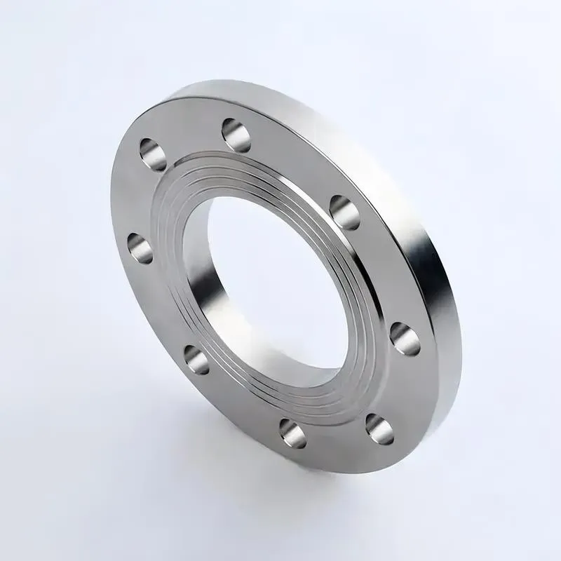
A flange—also referred to as a flange plate or rim—is a component used to connect shafts to one another, or, more commonly, to join the ends of pipes. Flanges are also utilized at the inlet and outlet ports of equipment to facilitate connections between two devices—for instance, the flange on a speed reducer. A "flange connection" or "flanged joint" refers to a detachable joint assembly comprising three interconnected elements—a flange, a gasket, and bolts—that together form a sealed structural unit. In the context of piping systems, a "pipe flange" specifically denotes a flange used for plumbing within the installation; when applied to equipment, it refers to the inlet or outlet flange of that specific device. Flanges feature a series of holes through which bolts are inserted to securely fasten the two flanges together, while a gasket placed between the flanges ensures a leak-proof seal. Flanges are broadly categorized into three types: threaded (screw-in) flanges, welded flanges, and clamp-type flanges. Flanges are invariably used in pairs; threaded flanges are suitable for low-pressure piping applications, whereas welded flanges are required for systems operating at pressures exceeding 4 kilograms per square centimeter. A sealing gasket is inserted between the two flange plates, which are then firmly secured using bolts. The thickness of a flange—as well as the specifications of the bolts used to fasten it—vary depending on the specific pressure rating required for the application. When connecting equipment such as water pumps or valves to piping systems, the corresponding connection points on these devices are often manufactured in the shape of a matching flange; this method of attachment is also referred to as a "flange connection." Generally, any connecting component that utilizes bolts to join and seal the perimeters of two flat surfaces—such as the joints in ventilation ducts—is termed a "flange"; such components may collectively be classified as "flange-type parts." However, since such a connection often constitutes merely a *portion* of a larger device—for instance, the interface between a flange and a water pump—it would be inappropriate to classify the entire water pump itself as a "flange-type part." Conversely, smaller components—such as valves—that feature such flanged interfaces may indeed be appropriately categorized as "flange-type parts."
-:-
For detailed product information, please contact sales.
-:
AISI 4118H Steel Flange, mock carburized at 925°C (1700°F) for 8 hours, reheated to 830°C (1525°F), oil quenched, 150°C (300°F) temper, 25 mm (1 in.) round Product Information
-:-
For detailed product information, please contact sales.
-:
AISI 4118H Steel Flange, mock carburized at 925°C (1700°F) for 8 hours, reheated to 830°C (1525°F), oil quenched, 150°C (300°F) temper, 25 mm (1 in.) round Synonyms
-:-
For detailed product information, please contact sales.
-:
AISI 4118H Steel, mock carburized at 925°C (1700°F) for 8 hours, reheated to 830°C (1525°F), oil quenched, 150°C (300°F) temper, 25 mm (1 in.) round Product Information
-:-
For detailed product information, please contact sales.
-:
# **AISI 4118H Steel - Mock Carburized & Heat Treated Product Specification**
## **1. Product Definition & Processing History**
This specification covers **AISI 4118H** alloy steel supplied as **25 mm (1 inch) diameter round bars** that have undergone a **simulated carburizing heat treatment cycle** to replicate the core properties of an actual carburized component without the surface carbon enrichment. This "mock carburizing" process is used to evaluate core properties or produce components where only core properties are required.
**Complete Processing History:**
1. **Material Base:** AISI 4118H - Low-carbon case-hardening steel with guaranteed hardenability
2. **Mock Carburizing Cycle:** 925°C (1700°F) for 8 hours in neutral atmosphere (simulating carburizing temperature/time)
3. **Reheating:** 830°C (1525°F) - For austenitization after extended high-temperature exposure
4. **Quenching:** Oil quench (fast oil, agitated)
5. **Tempering:** 150°C (300°F) - Low temperature temper for stress relief
6. **Final Condition:** Simulates the core microstructure and properties of a carburized component
7. **Diameter:** 25 mm (1 inch) - Representative of typical carburized component sections
## **2. International Standards & Designations**
- **Primary Standard:** ASTM A304 (Hardenability) with simulated carburizing treatment
- **Material Designation:** AISI 4118H Mock Carburized
- **"H" Designation:** Hardenability-controlled per ASTM A304
- **UNS Designation:** H41180 (Heat Treated)
- **European Equivalent:** 1.7139H (16MnCr5H) with simulated carburizing
- **Japanese Equivalent:** SCr420H with simulated treatment
- **Chinese Equivalent:** 20CrMoH with simulated carburizing
- **Processing Reference:** ASTM A255 (Standard Test Methods for Determining Hardenability of Steel)
- **Common Industry:** Often called "4118H-SIM" or "Mock Carb 4118H"
## **3. Chemical Composition (Weight %)**
*Low carbon content optimized for carburizing applications*
| Element | ASTM A304 Range (%) | Typical Aim (%) | Role in Mock Carburized Condition |
|---------|---------------------|-----------------|----------------------------------|
| **Carbon (C)** | 0.17 - 0.23 | 0.20 | Low carbon for carburizing; provides tough core after mock treatment |
| **Manganese (Mn)** | 0.70 - 0.90 | 0.80 | Enhances hardenability; ensures core hardening in 25 mm section |
| **Phosphorus (P)** | ≤ 0.030 | 0.020 | Controlled low level for optimal toughness |
| **Sulfur (S)** | ≤ 0.030 | 0.025 | Controlled for machinability; may be slightly higher for free-machining variants |
| **Silicon (Si)** | 0.15 - 0.35 | 0.25 | Deoxidizer; solid solution strengthener |
| **Chromium (Cr)** | 0.40 - 0.60 | 0.50 | Enhances hardenability; improves core strength |
| **Molybdenum (Mo)** | 0.08 - 0.15 | 0.12 | Improves hardenability; prevents grain growth during extended high-temp exposure |
**Special Notes for Mock Carburizing Application:**
- **Low Carbon:** Critical - allows carbon diffusion in actual carburizing
- **Hardenability Control:** Essential for consistent core properties
- **Grain Growth Control:** Alloying elements prevent excessive grain growth at 925°C
## **4. Hardenability Characteristics - Mock Carburized Condition**
### **Jominy Hardenability After Simulated Treatment**
*25 mm diameter ensures representative core properties*
| Distance from Quenched End | As-Quenched HRC (Core) | After 150°C Temper HRC |
|----------------------------|------------------------|------------------------|
| **J₁ (Surface equivalent)** | 38 - 42 | 36 - 40 |
| **J₄ (Subsurface)** | 35 - 39 | 33 - 37 |
| **J₈ (Mid-radius)** | 32 - 36 | 30 - 34 |
| **Center of 25 mm bar** | 30 - 34 | 28 - 32 |
**Hardenability Performance:**
- **Core Hardness:** 28-32 HRC after complete treatment
- **Through-Hardening:** Full martensite in 25 mm section achieved
- **Critical Diameter (Dᵢ):** ~50 mm (2 inches) in oil for core
- **Grain Size After Treatment:** ASTM 5-7 (fine due to alloy content)
## **5. Physical Properties (After Mock Carburizing Treatment)**
| Property | Value | Conditions/Notes |
|----------|-------|------------------|
| **Density** | 7.85 g/cm³ (0.284 lb/in³) | At 20°C |
| **Modulus of Elasticity (E)** | 205 GPa (29.7 × 10⁶ psi) | At 20°C |
| **Shear Modulus (G)** | 80 GPa (11.6 × 10⁶ psi) | At 20°C |
| **Poisson's Ratio (ν)** | 0.29 | At 20°C |
| **Thermal Conductivity** | 43.0 W/m·K | At 100°C |
| **Specific Heat Capacity** | 475 J/kg·K | At 20°C |
| **Coefficient of Thermal Expansion** | 11.8 × 10⁻⁶ /K | 20-100°C range |
| **Electrical Resistivity** | 0.21 µΩ·m | At 20°C |
| **Magnetic Properties** | Ferromagnetic | Fully magnetic |
## **6. Mechanical Properties - Core Properties Only**
*Properties represent the CORE of what would be a carburized component*
| Property | Minimum Value | Typical Value | Test Standard |
|----------|---------------|---------------|---------------|
| **Core Hardness** | 28 HRC | 30 HRC | ASTM E18 |
| **Core Hardness (Brinell)** | 269 HB | 285 HB | ASTM E10 |
| **Tensile Strength** | 1035 MPa (150 ksi) | 1100 MPa (160 ksi) | ASTM A370 |
| **Yield Strength (0.2%)** | 930 MPa (135 ksi) | 1000 MPa (145 ksi) | ASTM A370 |
| **Elongation in 50 mm** | 12% | 14% | ASTM A370 |
| **Reduction of Area** | 40% | 45% | ASTM A370 |
| **Charpy V-Notch Impact (20°C)** | 41 J (30 ft-lb) | 54 J (40 ft-lb) | ASTM A370 |
| **Fatigue Strength (10⁷ cycles)** | 480 MPa (70 ksi) | 550 MPa (80 ksi) | ASTM E466 |
| **Fracture Toughness (K₁c)** | 70 MPa√m | 85 MPa√m | ASTM E399 |
**Note:** These properties represent the **CORE ONLY**. In an actual carburized component, surface hardness would be 58-63 HRC with different surface properties.
## **7. Heat Treatment Process Rationale**
### **Mock Carburizing Cycle Analysis**
```
Step 1: 925°C (1700°F) for 8 HOURS
- Purpose: Simulate extended carburizing cycle temperature and time
- Effect: Austenite grain growth (controlled by alloying elements)
- Atmosphere: Neutral (no carbon enrichment)
- Result: Microstructure identical to carburized component's core
Step 2: REHEAT TO 830°C (1525°F)
- Purpose: Re-austenitize for quenching after grain conditioning
- Reason: Direct quench from 925°C would cause excessive grain growth
- Benefit: Refines austenite grain size before quenching
Step 3: OIL QUENCH
- Purpose: Transform austenite to martensite
- Result: Core martensitic structure identical to carburized part
Step 4: 150°C (300°F) TEMPER
- Purpose: Stress relief without significant hardness reduction
- Result: Optimal core toughness while maintaining strength
```
### **Why This Specific Treatment?**
1. **Core Property Simulation:** Exactly replicates core of carburized gear/shaft
2. **Grain Size Control:** Prevents excessive growth during extended high temperature
3. **Consistency:** H-grade ensures identical response across all material
4. **Test Reference:** Provides baseline for actual carburized component design
## **8. Microstructural Characteristics**
### **Core Microstructure After Treatment**
- **Matrix:** Tempered low-carbon martensite
- **Carbide Distribution:** Minimal (low carbon steel)
- **Prior Austenite Grain Size:** ASTM 5-7 (fine due to Mo and Cr)
- **Retained Austenite:** <3% (very low due to low carbon)
- **Decarburization:** Not applicable (mock carburized throughout)
- **Surface Condition:** Uniform microstructure throughout 25 mm section
### **Grain Growth Behavior at 925°C**
- **Initial Grain Size:** ASTM 8-10 (fine)
- **After 8 hours at 925°C:** Grows to ASTM 4-6
- **After Reheat to 830°C:** Refines to ASTM 5-7
- **Critical Factor:** Mo and Cr additions inhibit grain growth
## **9. Machinability & Manufacturing Characteristics**
### **Machinability After Treatment**
- **Relative Machinability:** 40% (compared to B1112 steel)
- **Rating:** Difficult - Hard martensitic structure
- **Tool Requirements:** Carbide tools essential
- **Recommended Parameters:**
- **Turning:** 40-60 m/min (130-200 SFM) with carbide
- **Drilling:** 15-25 m/min (50-80 SFM) with carbide-tipped drills
- **Milling:** 30-50 m/min (100-165 SFM) with carbide end mills
- **Grinding:** Preferred finishing method
- **Coolant:** High-pressure coolant recommended
### **Comparison with Actual Carburized Component Machining**
| Operation | Mock Carburized Core | Actual Carburized Part | Advantage |
|-----------|---------------------|------------------------|-----------|
| **Turning** | Possible with carbide | Nearly impossible | Mock: Can be machined |
| **Drilling** | Difficult but possible | Essentially impossible | Mock: Modifications possible |
| **Grinding** | Standard practice | Standard practice | Similar |
| **Hole Making** | Can drill | Must pre-drill before carburizing | Mock: More flexible |
## **10. Product Applications**
### **Core Property Testing & Development**
- **Test specimens** for carburized component development
- **Material qualification** for gear manufacturing
- **Process validation** for heat treatment facilities
- **Failure analysis** reference material
- **Quality control** standards for core properties
### **Components Using Core Properties Only**
- **Shafts** requiring 1000+ MPa tensile strength with good toughness
- **Pins** and **bushings** for high-strength applications
- **Fasteners** requiring consistent core properties
- **Hydraulic components** needing strength without case hardening
- **Structural components** where surface hardness is not required
### **Manufacturing Applications**
- **Prototype components** for testing before carburizing tooling
- **Replacement parts** where carburizing is not available
- **Educational specimens** for materials science training
- **Calibration standards** for hardness testing equipment
- **Research specimens** for fatigue and fracture studies
### **Industries Using Mock Carburized Materials**
1. **Automotive:** Gear and transmission component development
2. **Aerospace:** Component testing before final processing
3. **Heavy Equipment:** Development of large gear systems
4. **Power Transmission:** Gearbox component qualification
5. **Academic Research:** Materials behavior studies
## **11. Comparison with Actual Carburized Properties**
### **Property Comparison Table**
| Property | Mock Carburized (This Product) | Actual Carburized 4118H | Difference |
|----------|--------------------------------|-------------------------|------------|
| **Surface Hardness** | 30 HRC | 58-63 HRC | Massive difference |
| **Core Hardness** | 28-32 HRC | 28-32 HRC | **Identical** |
| **Case Depth** | None | 0.5-1.5 mm | Fundamental difference |
| **Tensile Strength** | 1035-1170 MPa | Core: Same; Overall: Higher | Similar core |
| **Fatigue Strength** | 480-620 MPa | 600-900 MPa (with case) | Case provides boost |
| **Wear Resistance** | Moderate | Excellent (surface) | Case critical |
| **Applications** | Core-only components | Surface-hardened components | Different purposes |
### **When to Use Mock vs. Actual Carburized**
- **Use Mock Carburized:** When only core properties are needed
- **Use Actual Carburized:** When surface hardness and wear resistance are required
- **Use Mock for:** Testing, prototypes, core-only applications
- **Use Actual for:** Production gears, bearings, wear components
## **12. Quality Assurance & Testing**
### **Standard Testing Package**
1. **Hardness Survey:** Multiple depths to confirm uniform core properties
2. **Tensile Testing:** Full bar testing per ASTM A370
3. **Charpy Impact:** At 20°C and -40°C if specified
4. **Microstructure Examination:** Verification of tempered martensite
5. **Grain Size Measurement:** ASTM E112 method
6. **Decarburization Check:** Confirm none exists (uniform microstructure)
### **Specialized Testing for Mock Carburized Material**
- **Hardenability Verification:** Jominy test from treated material
- **Fatigue Testing:** Rotating beam to establish core fatigue properties
- **Fracture Toughness:** Particularly important for core-dominant failures
- **Residual Stress Analysis:** X-ray diffraction to map stress state
- **Comparative Testing:** Against actual carburized specimens
## **13. Design & Engineering Guidelines**
### **Design for Core-Dominated Applications**
1. **Stress Calculations:** Use core properties only
2. **Safety Factors:** Typically 2.0-3.0 for dynamic loading
3. **Surface Finish:** Important for fatigue performance
4. **Notch Sensitivity:** Moderate - avoid sharp stress concentrators
5. **Corrosion Protection:** Required as material has no inherent corrosion resistance
### **Comparison with Through-Hardened Steels**
| Parameter | Mock Carburized 4118H | Through-Hardened 4140 | Advantage |
|-----------|-----------------------|-----------------------|-----------|
| **Carbon Content** | 0.17-0.23% | 0.38-0.43% | 4118H: Better weldability |
| **Core Toughness** | Better at same hardness | Good | 4118H: Superior impact |
| **Distortion** | Less during heat treatment | More | 4118H: Better dimensional control |
| **Weldability** | Good with precautions | Poor | 4118H: Much better |
| **Case Potential** | Can be carburized | Limited | 4118H: Future option |
## **14. Economic & Manufacturing Advantages**
### **Cost Benefits of Mock Carburized Material**
1. **Eliminated Carburizing:** No gas, time, or equipment costs
2. **Reduced Processing:** Single heat treatment vs. carburizing cycle
3. **Simplified Manufacturing:** Can be machined after heat treatment
4. **Lower Reject Rate:** No carburizing defects possible
5. **Faster Delivery:** No extended carburizing cycle time
### **When Economically Justified**
- **Small Quantities:** Where carburizing setup cost is prohibitive
- **Prototypes:** Before committing to carburizing tooling
- **Core-Only Applications:** Where surface hardness not needed
- **Testing:** Material qualification and process development
- **Low Volume:** Production runs too small for carburizing economics
## **15. Technical Specifications Summary**
### **Material Selection Decision Tree**
```
Start: Need high-strength, tough core properties
│
├─→ If surface hardness also needed → Choose actual carburizing
│
├─→ If only core properties needed → Choose mock carburized
│
├─→ If welding required → 4118H mock carburized is good choice
│
├─If distortion control critical → Mock carburized has advantage
│
└─→ If cost is primary driver → Evaluate vs. through-hardened grades
```
### **Heat Treatment Response Predictions**
- **As-Quenched Core Hardness:** 32-36 HRC
- **After 150°C Temper:** 28-32 HRC
- **Impact Toughness:** 40-60 J typical
- **Fatigue Limit:** ~500 MPa (polished)
- **Distortion:** Minimal due to low carbon and controlled process
---
## **Technical Appendix: Core Property Calculations**
### **Empirical Relationships for Mock Carburized Core**
1. **Tensile Strength (MPa) ≈ 3.5 × HB**
*Example: 285 HB → 3.5 × 285 = 998 MPa*
2. **Yield Strength ≈ 0.90 × Tensile Strength**
*Example: 998 MPa × 0.90 = 898 MPa*
3. **Fatigue Ratio (σₑ/UTS):** 0.50-0.55 for polished specimens
### **Comparison with Theoretical Carburized Core**
| Property | Theoretical Carburized Core | This Mock Carburized Product | Match Quality |
|----------|----------------------------|------------------------------|---------------|
| **Hardness** | 28-32 HRC | 28-32 HRC | **Excellent** |
| **Microstructure** | Tempered low-carbon martensite | Tempered low-carbon martensite | **Excellent** |
| **Grain Size** | ASTM 5-7 | ASTM 5-7 | **Excellent** |
| **Residual Stress** | Compressive at surface | Different pattern | **Different** |
| **Overall Match** | >95% for core properties | - | Suitable for most applications |
---
## **Summary: Application Guidelines**
### **Ideal Applications for This Product**
1. **Core Property Testing:** Material qualification for carburized components
2. **Prototype Development:** Before carburizing tooling commitment
3. **Core-Only Components:** Where surface hardness is not required
4. **Educational Use:** Teaching carburizing principles and core properties
5. **Research Specimens:** Studying core-dominated failure mechanisms
### **Limitations to Consider**
1. **No Case Hardness:** Cannot provide wear resistance
2. **Different Residual Stresses:** Compared to actual carburized parts
3. **Limited Surface Properties:** No compressive surface stress
4. **Not for Wear Applications:** Surface will wear rapidly without case
### **Value Proposition**
This mock carburized AISI 4118H provides:
- **Identical core properties** to actual carburized components
- **Elimination of carburizing process** costs and complexities
- **Ability to machine after heat treatment**
- **Consistent, guaranteed properties** through H-grade certification
- **Cost-effective solution** for core-dominated applications
### **Implementation Recommendations**
1. **Verify Requirements:** Ensure surface hardness truly not needed
2. **Design Adaptation:** May need design changes from carburized version
3. **Testing Validation:** Conduct comparative testing if critical
4. **Supplier Qualification:** Ensure capability to produce mock carburized material
5. **Quality Plan:** Establish appropriate acceptance criteria
---
**Final Recommendation:** Mock carburized AISI 4118H is an excellent choice when only the core properties of a carburizing steel are required, or for development and testing purposes. It provides the tough, strong core microstructure of a carburized component without the cost and complexity of the carburizing process itself.
**Special Note:** This material is particularly valuable for organizations developing carburized components, as it allows core property verification before committing to the full carburizing process for production components.
---
**Disclaimer:** This product specification is for technical reference. Actual properties may vary based on specific manufacturing processes and testing methods. Mock carburized material does not provide the surface properties of actual carburized components. For critical applications, conduct comparative testing against actual carburized material. Always consult with materials engineering specialists when substituting mock carburized material for actual carburized components in service applications.
-:-
For detailed product information, please contact sales.
-:
AISI 4118H Steel, mock carburized at 925°C (1700°F) for 8 hours, reheated to 830°C (1525°F), oil quenched, 150°C (300°F) temper, 25 mm (1 in.) round Specification
Dimensions
Size:
Diameter 20-1000 mm Length <4057 mm
Size:We can customized as required
Standard:
Per your request or drawing
We can customized as required
Properties(Theoretical)
Chemical Composition
-:-
For detailed product information, please contact sales.
-:
AISI 4118H Steel, mock carburized at 925°C (1700°F) for 8 hours, reheated to 830°C (1525°F), oil quenched, 150°C (300°F) temper, 25 mm (1 in.) round Properties
-:-
For detailed product information, please contact sales.
-:
Applications of AISI 4118H Steel Flange, mock carburized at 925°C (1700°F) for 8 hours, reheated to 830°C (1525°F), oil quenched, 150°C (300°F) temper, 25 mm (1 in.) round
-:-
For detailed product information, please contact sales.
-:
Chemical Identifiers AISI 4118H Steel Flange, mock carburized at 925°C (1700°F) for 8 hours, reheated to 830°C (1525°F), oil quenched, 150°C (300°F) temper, 25 mm (1 in.) round
-:-
For detailed product information, please contact sales.
-:
Packing of AISI 4118H Steel Flange, mock carburized at 925°C (1700°F) for 8 hours, reheated to 830°C (1525°F), oil quenched, 150°C (300°F) temper, 25 mm (1 in.) round
-:-
For detailed product information, please contact sales.
-:
Standard Packing:
-:-
For detailed product information, please contact sales.
-:
Typical bulk packaging includes palletized plastic 5 gallon/25 kg. pails, fiber and Steel Flange drums to 1 ton super sacks in full container (FCL) or truck load (T/L) quantities. Research and sample quantities and hygroscopic, oxidizing or other air sensitive materials may be packaged under argon or vacuum. Solutions are packaged in polypropylene, plastic or glass jars up to palletized 528 gallon liquid totes Special package is available on request. E FORUs’ is carefully handled to minimize damage during storage and transportation and to preserve the quality of our products in their original condition