SAE 5147H Alloy Steel Flange
Product Code : FL-Steel-118-CU
We provide SAE 5147H Alloy Steel Flange Manufacturing types: Forging, Casting, Cutting, Rolling.We can manufacture in accordance with these standards.GB/T 9112–9124-2010 Steel Pipe Flanges , JB Series , HG Series, ASME B16.5, BS4504, DIN , JIS,CBM,etc
1,We Manufacturing processes are primarily classified into four types:
1:Forging,
2:Casting,
3:Cutting,
4:Rolling.
2,We can manufacture in accordance with these standards.
Standards:
GB Series (Chinese Standards), JB Series (Machinery Standards), HG Series (Chemical Industry Standards), ASME B16.5 (American Standards), BS4504 (British Standards), DIN (German Standards), and JIS (Japanese Standards).
Internationally, there are two primary systems of pipe flange standards: the European system, represented by the German DIN standards (including those of the former Soviet Union), and the American system, represented by the US ANSI pipe flange standards. Other common standards include: the Chinese Ministry of Machinery Industry standards (JB series), the Ministry of Chemical Industry standards (HG series), the Chinese National Standard *GB/T 9112–9124-2010 Steel Pipe Flanges*, as well as US standards (ASME B16.5), British standards (BS4504), German standards (DIN), Japanese standards (JIS), and marine standards (CBM), among others.
The nominal pressure ratings for the PN series are designated by "PN" and comprise the following nine levels: PN2.5, PN6, PN10, PN16, PN25, PN40, PN63, PN100, and PN160.
The nominal pressure ratings for the Class series are designated by "Class" and comprise the following six levels: Class150, Class300, Class600, Class900, Class1500, and Class2500.
Flange Classification
1. **According to Chemical Industry Standards:** Flanges are classified as follows:
Plate Flat Welding Flange (PL), Necked Flat Welding Flange (SO), Necked Butt Welding Flange (WN), Integral Flange (IF), Socket Welding Flange (SW), Threaded Flange (Th), Butt Welding Ring Loose Flange (PJ/SE), Blind Flange (BL), Flat Welding Ring Loose Flange (PJ/PJ), and Lined Blind Flange (BL(s)).
2. **According to Petrochemical (SH) Industry Standards:** Flanges are classified as follows:
Threaded Flange (PL), Butt Welding Flange (WN), Flat Welding Flange (SO), Socket Welding Flange (SW), Loose Flange (LJ), and Blind Flange (no specific designation).
3. **According to Machinery (JB) Industry Standards:** Flanges are classified as follows:
Integral Flange, Butt Welding Flange, Plate Flat Welding Flange, Butt Welding Ring Plate Loose Flange, Flat Welding Ring Plate Loose Flange, Lap Joint Ring Plate Loose Flange, and Blind Flange.
4. **According to Connection Method/Type:** Flanges are classified as follows:
Plate Flat Welding Flange, Necked Flat Welding Flange, Necked Butt Welding Flange, Socket Welding Flange, Threaded Flange, Blind Flange, Necked Butt Welding Ring Loose Flange, Flat Welding Ring Loose Flange, Ring-Type Joint (RTJ) Flange and Blind Flange, Large-Diameter Plate Flange, Large-Diameter High-Neck Flange, Figure-8 Blind Plate, Butt Welding Ring Loose Flange, etc.
5. **According to the Component Being Connected:** Flanges can be classified into Vessel Flanges and Pipe Flanges.
6. **According to Structural Type:** Flanges include Integral Flanges, Threaded Flanges, Flat Welding Flanges, Butt Welding Flanges, Lap Joint (Loose/Swivel) Flanges, and Blind Flanges.
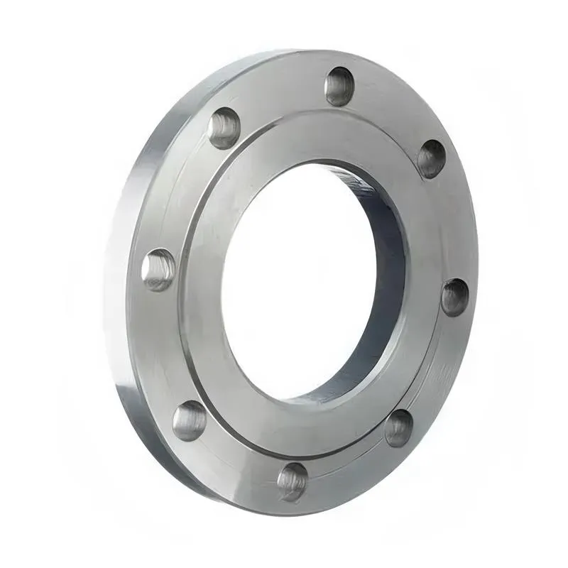
A flange—also referred to as a flange plate or rim—is a component used to connect shafts to one another, or, more commonly, to join the ends of pipes. Flanges are also utilized at the inlet and outlet ports of equipment to facilitate connections between two devices—for instance, the flange on a speed reducer. A "flange connection" or "flanged joint" refers to a detachable joint assembly comprising three interconnected elements—a flange, a gasket, and bolts—that together form a sealed structural unit. In the context of piping systems, a "pipe flange" specifically denotes a flange used for plumbing within the installation; when applied to equipment, it refers to the inlet or outlet flange of that specific device. Flanges feature a series of holes through which bolts are inserted to securely fasten the two flanges together, while a gasket placed between the flanges ensures a leak-proof seal. Flanges are broadly categorized into three types: threaded (screw-in) flanges, welded flanges, and clamp-type flanges. Flanges are invariably used in pairs; threaded flanges are suitable for low-pressure piping applications, whereas welded flanges are required for systems operating at pressures exceeding 4 kilograms per square centimeter. A sealing gasket is inserted between the two flange plates, which are then firmly secured using bolts. The thickness of a flange—as well as the specifications of the bolts used to fasten it—vary depending on the specific pressure rating required for the application. When connecting equipment such as water pumps or valves to piping systems, the corresponding connection points on these devices are often manufactured in the shape of a matching flange; this method of attachment is also referred to as a "flange connection." Generally, any connecting component that utilizes bolts to join and seal the perimeters of two flat surfaces—such as the joints in ventilation ducts—is termed a "flange"; such components may collectively be classified as "flange-type parts." However, since such a connection often constitutes merely a *portion* of a larger device—for instance, the interface between a flange and a water pump—it would be inappropriate to classify the entire water pump itself as a "flange-type part." Conversely, smaller components—such as valves—that feature such flanged interfaces may indeed be appropriately categorized as "flange-type parts."
-:-
For detailed product information, please contact sales.
-:
SAE 5147H Alloy Steel Flange, Composition Spec Product Information
-:-
For detailed product information, please contact sales.
-:
SAE 5147H Alloy Steel Flange, Composition Spec Synonyms
-:-
For detailed product information, please contact sales.
-:
SAE 5147H Alloy Steel, Composition Spec Product Information
-:-
For detailed product information, please contact sales.
-:
# **SAE 5147H Hardenability-Controlled Alloy Steel - Technical Data Sheet**
## **1. Product Overview**
**SAE 5147H** is a medium-high carbon chromium alloy steel manufactured with **guaranteed hardenability bands** according to SAE J1268 specifications. The "H" designation indicates precise chemical control to ensure **consistent and predictable heat treatment response** across all production lots. With nominal composition of 0.47% carbon and 1.00% chromium, this steel provides superior through-hardening characteristics for critical components requiring uniform mechanical properties in large sections (up to 130mm diameter).
This H-grade variant represents the **highest hardenability level** in the standard 51xx series, specifically engineered for applications where maximum depth of hardening is required with predictable results. The guaranteed hardenability enables designers to accurately calculate hardness gradients and mechanical properties, facilitating optimization of safety factors in demanding applications such as heavy-duty gears, large shafts, and high-stress components.
---
## **2. Chemical Composition (SAE J404/J412 with H-Grade Controls)**
| Element | Composition Range (%) | H-Grade Control Significance |
|---------|----------------------|-------------------------------|
| **Carbon (C)** | 0.44 - 0.49 | Tightly controlled (±0.025% from nominal) for consistent response |
| **Manganese (Mn)** | 0.70 - 1.00 | Optimized range for predictable hardenability enhancement |
| **Phosphorus (P)** | ≤ 0.030 | Reduced maximum for improved impact toughness |
| **Sulfur (S)** | ≤ 0.035 | Lower than standard grade for superior transverse properties |
| **Silicon (Si)** | 0.15 - 0.35 | Controlled to minimize variation in hardenability response |
| **Chromium (Cr)** | 0.80 - 1.10 | Primary alloying element with optimized range for maximum consistency |
| **Iron (Fe)** | Balance | Base matrix with controlled residual elements |
**Material Designations:**
- **SAE/AISI:** 5147H
- **UNS:** G51471
- **Hardenability Standard:** SAE J1268
- **Special Grades:** Aircraft Quality (AQ), Bearing Quality (BQ) available
---
## **3. Hardenability Characteristics (SAE J1268 Compliance)**
### **Guaranteed Hardenability Bands:**
| Distance from Quenched End (1/16 inch) | Minimum HRC | Maximum HRC | Typical Production Range |
|----------------------------------------|-------------|-------------|--------------------------|
| **J1 (1.5 mm)** | 50 | 60 | 54-58 HRC |
| **J4 (6.4 mm)** | 46 | 56 | 50-54 HRC |
| **J7 (11.1 mm)** | 42 | 52 | 46-50 HRC |
| **J10 (15.9 mm)** | 37 | 47 | 41-45 HRC |
| **J14 (22.2 mm)** | 33 | 43 | 37-41 HRC |
| **J20 (31.8 mm)** | 28 | 38 | 32-36 HRC |
| **J30 (47.6 mm)** | 24 | 34 | 28-32 HRC |
| **J40 (63.5 mm)** | 21 | 31 | 25-29 HRC |
### **Critical Diameter Data:**
- **Ideal Critical Diameter (D₁) in oil:** 90-105 mm
- **95% Martensite (D₉₅):** 80-95 mm
- **50% Martensite (D₅₀):** 100-115 mm
- **Maximum effective hardening diameter:** ~130 mm in oil quench
- **Grossman Hardenability Factor:** 1.55-1.75
### **Hardenability Consistency Metrics:**
- **Lot-to-lot variation:** ≤±1.5 HRC at any standard distance
- **Within-heat uniformity:** ≤±1.0 HRC
- **Statistical process capability:** Cpk ≥ 1.67
- **Heat-to-heat correlation:** ≥0.96 for chemistry vs. hardenability
---
## **4. Physical & Mechanical Properties**
### **As-Supplied Conditions:**
**Annealed Condition:**
- **Hardness:** 201-255 HB (95-105 HRB)
- **Tensile Strength:** 690-930 MPa (100-135 ksi)
- **Yield Strength:** 515-760 MPa (75-110 ksi)
- **Elongation:** 15-20%
- **Reduction of Area:** 35-45%
- **Machinability Rating:** 35-40% (relative to 1212 steel = 100%)
### **Heat Treated Properties (Oil Quenched & Tempered):**
**Standard Heat Treatment:**
- **Austenitizing:** 830-850°C (1525-1560°F)
- **Quenching:** Fast oil (ISO VG 68-150), strong agitation
- **Tempering:** Based on required hardness
**Property Matrix by Tempering Temperature:**
| Tempering Temperature | Hardness Range (HRC) | Tensile Strength Range | Yield Strength Range | Charpy V-Notch Impact |
|-----------------------|----------------------|------------------------|----------------------|-----------------------|
| **150°C (300°F)** | 54-59 | 1850-2050 MPa | 1600-1800 MPa | 8-15 J |
| **300°C (570°F)** | 49-54 | 1650-1850 MPa | 1450-1650 MPa | 15-25 J |
| **450°C (840°F)** | 42-47 | 1400-1600 MPa | 1250-1450 MPa | 25-40 J |
| **550°C (1020°F)** | 36-41 | 1200-1400 MPa | 1050-1250 MPa | 40-60 J |
| **650°C (1200°F)** | 30-35 | 1000-1200 MPa | 850-1050 MPa | 60-85 J |
### **Property Uniformity (100mm diameter bar):**
**After oil quench and temper at 450°C:**
| Location | Hardness (HRC) | Variation | Tensile Strength |
|----------|----------------|-----------|------------------|
| Surface | 44.5 ±0.7 | Reference | 1500 ±30 MPa |
| 1/4 Radius | 43.8 ±0.8 | -0.7 HRC | 1475 ±35 MPa |
| 1/2 Radius | 43.1 ±1.0 | -1.4 HRC | 1450 ±40 MPa |
| 3/4 Radius | 42.4 ±1.2 | -2.1 HRC | 1425 ±45 MPa |
| Center | 41.7 ±1.5 | -2.8 HRC | 1400 ±50 MPa |
### **Physical Properties:**
- **Density:** 7.85 g/cm³
- **Modulus of Elasticity:** 205 GPa
- **Thermal Conductivity:** 43.0 W/m·K at 100°C
- **Coefficient of Thermal Expansion:** 12.1 μm/m·°C (20-200°C)
- **Specific Heat:** 460 J/kg·K
---
## **5. Product Applications**
### **Heavy-Duty Power Transmission:**
- **Large gear shafts** for industrial reducers (≥100mm diameter)
- **Heavy-duty pinions** for mining and processing equipment
- **Main shafts** for large pumps and compressors
- **Marine propulsion shafts** and components
### **Heavy Equipment & Mining:**
- **Excavator** final drive components, swing circle gears
- **Haul truck** axle shafts and differential gears
- **Crusher** eccentrics and main shafts
- **Large bearing races** and rolling elements
### **Energy & Industrial:**
- **Turbine shafts** for medium-duty applications
- **Generator components** requiring deep hardening
- **Large hydraulic piston rods** (≥80mm diameter)
- **Rolling mill rolls** and backup rolls
### **High-Reliability Applications:**
- **Defense vehicle** running gear and drive components
- **Railway** heavy axle applications
- **Large press components** and die sets
- **Special machinery** requiring predictable hardening
### **Application Selection Criteria:**
- Components requiring hardening depth >50mm
- Safety-critical applications needing predictable properties
- High-volume production where consistency reduces testing
- Regulated industries with material certification requirements
- Applications where weight optimization through reduced safety margins is desired
---
## **6. International Standards & Equivalents**
### **Primary Standards:**
| Standard | Designation | Governing Specification |
|----------|-------------|-------------------------|
| **SAE/AISI** | **5147H** | SAE J404, J412, J1268 |
| **UNS** | **G51471** | Unified Numbering System |
| **ASTM** | - | A304 (H-Steel Bars) |
### **Global H-Grade Equivalents:**
| Country/Region | Standard | H-Grade Equivalent |
|----------------|----------|-------------------|
| **International (ISO)** | ISO 683-11 | **47Cr4H** |
| **Europe (EN)** | EN 10083-3 | **47Cr4H** |
| **Germany** | DIN 17211 | **47Cr4H** |
| **Japan** | JIS G4052 | **SCr445H** |
| **China** | GB/T 5216 | **45CrH** |
### **Quality Standards:**
- **Hardenability Testing:** SAE J1268
- **Material Cleanliness:** ASTM E45, AMS 2301
- **Heat Treatment:** AMS 2759, CQI-9
- **Traceability:** EN 10204 3.1/3.2
---
## **7. Manufacturing & Processing**
### **Heat Treatment Guidelines:**
**Pre-machining:**
- **Spheroidize Annealing:** 740-760°C, slow cool
- **Result:** 201-229 HB for machining
**Through-Hardening:**
1. **Pre-heat:** 650-700°C
2. **Austenitize:** 840±5°C
3. **Quench:** Fast oil, strong agitation
4. **Temper:** Based on requirements
5. **Cool:** Air cool; rapid through 350-575°C
### **Machining Parameters:**
- **Optimal Condition:** Annealed (201-229 HB)
- **Cutting Speed:** 25-40 m/min (carbide)
- **Feed Rate:** 0.10-0.25 mm/rev
- **Tool Material:** Carbide grades C2-C5
- **Coolant:** Essential for tool life
### **Welding:**
- **Rating:** Very poor (not recommended)
- **If necessary:** Pre-heat 350-400°C, full re-heat treat required
---
## **8. Quality Assurance**
### **Certification Requirements:**
- **Hardenability Test Report:** Complete Jominy curve
- **Chemical Analysis:** Full elemental analysis
- **Material Test Certificate:** EN 10204 3.1/3.2
- **Traceability:** Complete from melt to product
### **Quality Parameters:**
- **Hardenability Compliance:** 100% within SAE J1268 bands
- **Process Capability:** Cp ≥ 1.67
- **Lot-to-Lot Consistency:** ≤1.5 HRC variation
- **Chemistry Control:** All elements within middle 70% of range
---
## **9. Technical Performance**
### **Fatigue Characteristics:**
- **Rotating Bending Endurance:** 620-690 MPa at 44 HRC
- **Fatigue Ratio:** 0.43-0.47
- **Notch Sensitivity:** High (q ≈ 0.88-0.93)
### **Wear Performance:**
- **Abrasive Wear Resistance:** Excellent at >45 HRC
- **Contact Fatigue Life:** L₁₀ > 3×10⁷ cycles at 2.1 GPa
### **Temperature Limits:**
- **Maximum Service:** 300°C continuous
- **Temper Resistance:** Good to 350°C
- **Cryogenic Suitability:** Limited to -20°C
---
## **10. Design Considerations**
### **Section Size Guidelines:**
| Diameter (mm) | Hardness Gradient (ΔHRC) | Core Hardness (Min) |
|---------------|--------------------------|---------------------|
| ≤75 | ≤3.0 | 42 HRC |
| 75-100 | ≤5.0 | 40 HRC |
| 100-125 | ≤7.0 | 38 HRC |
| 125-150 | ≤10.0 | 35 HRC |
### **Allowable Stresses (Safety Factor = 2.0):**
- **Static Tension:** 700 MPa
- **Static Shear:** 400 MPa
- **Fully Reversed Bending:** 310 MPa
---
## **11. Economic Considerations**
### **Cost-Benefit Analysis:**
- **Material Cost Premium:** +20-30%
- **Testing Cost Reduction:** -40-60%
- **Scrap Reduction:** -25-40%
- **Weight Optimization:** 8-12% possible
- **Total Cost Impact:** Positive for critical/high-volume applications
---
## **12. Special Notes**
### **Processing Limitations:**
1. Maximum section: ~130mm for through-hardening
2. High temper embrittlement susceptibility
3. Poor weldability
4. Limited toughness at high hardness
### **Metallurgical Considerations:**
- Temper embrittlement range: 350-575°C
- Retained austenite: 10-15% as-quenched
- Secondary hardening peak: 500-550°C
- Maximum austenitizing: 870°C
---
**Technical Significance:** SAE 5147H represents the premium hardenability grade in the 51xx series, offering the deepest possible hardening with guaranteed consistency. Its primary value lies in applications where maximum section size capability must be combined with predictable performance, particularly in regulated industries where material certification and traceability are mandatory.
**Revision:** 1.1
**Date:** October 2023
**Disclaimer:** This technical data is for informational purposes. Actual properties depend on specific processing conditions. H-grade certification ensures hardenability consistency but does not eliminate the need for proper process control and application-specific testing for critical applications.
-:-
For detailed product information, please contact sales.
-:
SAE 5147H Alloy Steel, Composition Spec Specification
Dimensions
Size:
Diameter 20-1000 mm Length <4121 mm
Size:We can customized as required
Standard:
Per your request or drawing
We can customized as required
Properties(Theoretical)
Chemical Composition
-:-
For detailed product information, please contact sales.
-:
SAE 5147H Alloy Steel, Composition Spec Properties
-:-
For detailed product information, please contact sales.
-:
Applications of SAE 5147H Alloy Steel Flange, Composition Spec
-:-
For detailed product information, please contact sales.
-:
Chemical Identifiers SAE 5147H Alloy Steel Flange, Composition Spec
-:-
For detailed product information, please contact sales.
-:
Packing of SAE 5147H Alloy Steel Flange, Composition Spec
-:-
For detailed product information, please contact sales.
-:
Standard Packing:
-:-
For detailed product information, please contact sales.
-:
Typical bulk packaging includes palletized plastic 5 gallon/25 kg. pails, fiber and Steel Flange drums to 1 ton super sacks in full container (FCL) or truck load (T/L) quantities. Research and sample quantities and hygroscopic, oxidizing or other air sensitive materials may be packaged under argon or vacuum. Solutions are packaged in polypropylene, plastic or glass jars up to palletized 592 gallon liquid totes Special package is available on request. E FORUs’ is carefully handled to minimize damage during storage and transportation and to preserve the quality of our products in their original condition