1,We Manufacturing processes are primarily classified into four types:
1:Forging,
2:Casting,
3:Cutting,
4:Rolling.
2,We can manufacture in accordance with these standards.
Standards:
GB Series (Chinese Standards), JB Series (Machinery Standards), HG Series (Chemical Industry Standards), ASME B16.5 (American Standards), BS4504 (British Standards), DIN (German Standards), and JIS (Japanese Standards).
Internationally, there are two primary systems of pipe flange standards: the European system, represented by the German DIN standards (including those of the former Soviet Union), and the American system, represented by the US ANSI pipe flange standards. Other common standards include: the Chinese Ministry of Machinery Industry standards (JB series), the Ministry of Chemical Industry standards (HG series), the Chinese National Standard *GB/T 9112–9124-2010 Steel Pipe Flanges*, as well as US standards (ASME B16.5), British standards (BS4504), German standards (DIN), Japanese standards (JIS), and marine standards (CBM), among others.
The nominal pressure ratings for the PN series are designated by "PN" and comprise the following nine levels: PN2.5, PN6, PN10, PN16, PN25, PN40, PN63, PN100, and PN160.
The nominal pressure ratings for the Class series are designated by "Class" and comprise the following six levels: Class150, Class300, Class600, Class900, Class1500, and Class2500.
Flange Classification
1. **According to Chemical Industry Standards:** Flanges are classified as follows:
Plate Flat Welding Flange (PL), Necked Flat Welding Flange (SO), Necked Butt Welding Flange (WN), Integral Flange (IF), Socket Welding Flange (SW), Threaded Flange (Th), Butt Welding Ring Loose Flange (PJ/SE), Blind Flange (BL), Flat Welding Ring Loose Flange (PJ/PJ), and Lined Blind Flange (BL(s)).
2. **According to Petrochemical (SH) Industry Standards:** Flanges are classified as follows:
Threaded Flange (PL), Butt Welding Flange (WN), Flat Welding Flange (SO), Socket Welding Flange (SW), Loose Flange (LJ), and Blind Flange (no specific designation).
3. **According to Machinery (JB) Industry Standards:** Flanges are classified as follows:
Integral Flange, Butt Welding Flange, Plate Flat Welding Flange, Butt Welding Ring Plate Loose Flange, Flat Welding Ring Plate Loose Flange, Lap Joint Ring Plate Loose Flange, and Blind Flange.
4. **According to Connection Method/Type:** Flanges are classified as follows:
Plate Flat Welding Flange, Necked Flat Welding Flange, Necked Butt Welding Flange, Socket Welding Flange, Threaded Flange, Blind Flange, Necked Butt Welding Ring Loose Flange, Flat Welding Ring Loose Flange, Ring-Type Joint (RTJ) Flange and Blind Flange, Large-Diameter Plate Flange, Large-Diameter High-Neck Flange, Figure-8 Blind Plate, Butt Welding Ring Loose Flange, etc.
5. **According to the Component Being Connected:** Flanges can be classified into Vessel Flanges and Pipe Flanges.
6. **According to Structural Type:** Flanges include Integral Flanges, Threaded Flanges, Flat Welding Flanges, Butt Welding Flanges, Lap Joint (Loose/Swivel) Flanges, and Blind Flanges.
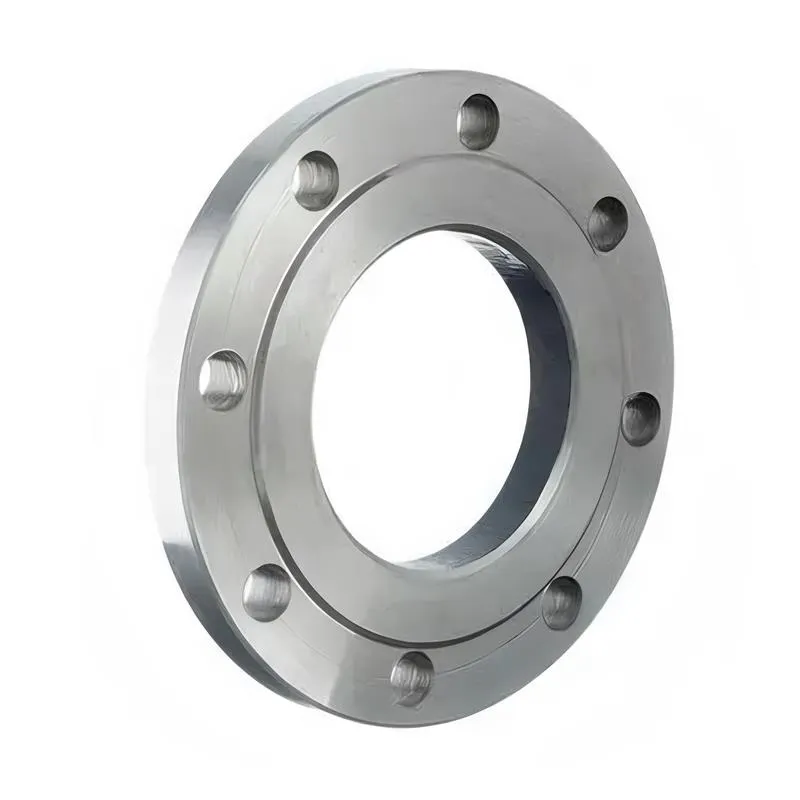
A flange—also referred to as a flange plate or rim—is a component used to connect shafts to one another, or, more commonly, to join the ends of pipes. Flanges are also utilized at the inlet and outlet ports of equipment to facilitate connections between two devices—for instance, the flange on a speed reducer. A "flange connection" or "flanged joint" refers to a detachable joint assembly comprising three interconnected elements—a flange, a gasket, and bolts—that together form a sealed structural unit. In the context of piping systems, a "pipe flange" specifically denotes a flange used for plumbing within the installation; when applied to equipment, it refers to the inlet or outlet flange of that specific device. Flanges feature a series of holes through which bolts are inserted to securely fasten the two flanges together, while a gasket placed between the flanges ensures a leak-proof seal. Flanges are broadly categorized into three types: threaded (screw-in) flanges, welded flanges, and clamp-type flanges. Flanges are invariably used in pairs; threaded flanges are suitable for low-pressure piping applications, whereas welded flanges are required for systems operating at pressures exceeding 4 kilograms per square centimeter. A sealing gasket is inserted between the two flange plates, which are then firmly secured using bolts. The thickness of a flange—as well as the specifications of the bolts used to fasten it—vary depending on the specific pressure rating required for the application. When connecting equipment such as water pumps or valves to piping systems, the corresponding connection points on these devices are often manufactured in the shape of a matching flange; this method of attachment is also referred to as a "flange connection." Generally, any connecting component that utilizes bolts to join and seal the perimeters of two flat surfaces—such as the joints in ventilation ducts—is termed a "flange"; such components may collectively be classified as "flange-type parts." However, since such a connection often constitutes merely a *portion* of a larger device—for instance, the interface between a flange and a water pump—it would be inappropriate to classify the entire water pump itself as a "flange-type part." Conversely, smaller components—such as valves—that feature such flanged interfaces may indeed be appropriately categorized as "flange-type parts."
-:-
For detailed product information, please contact sales.
-:
AISI 5120H Steel Flange, heat treated, machined to 25 mm, pseudocarburized, reheated to 775°C (1430°F), 150°C (300°F) temper Product Information
-:-
For detailed product information, please contact sales.
-:
AISI 5120H Steel Flange, heat treated, machined to 25 mm, pseudocarburized, reheated to 775°C (1430°F), 150°C (300°F) temper Synonyms
-:-
For detailed product information, please contact sales.
-:
AISI 5120H Steel, heat treated, machined to 25 mm, pseudocarburized, reheated to 775°C (1430°F), 150°C (300°F) temper Product Information
-:-
For detailed product information, please contact sales.
-:
# **AISI 5120H Steel - Controlled Hardenability Special Processing Specification**
## **1. Product Overview & Processing Summary**
**AISI 5120H steel processed under the specified conditions** represents a **premium-grade case hardening steel** subjected to a controlled thermomechanical sequence designed to develop optimal core properties with guaranteed hardenability response. The "H" suffix indicates chemistry controlled to specific hardenability bands per SAE J1268, ensuring consistent performance across production lots.
This specialized processing route combines initial hardening, precision machining, simulated carburizing thermal exposure, and intercritical heat treatment to produce a material with **predictable and uniform mechanical properties** in the final machined condition. The process is particularly valuable for components requiring dimensional stability, consistent core properties, and reliable fatigue performance without an actual carburized case.
**Complete Processing Sequence:**
1. **Initial Austenitizing & Quenching:** From 870-900°C (1600-1650°F)
2. **Tempering:** For machinability (typically 300-400°C)
3. **Precision Machining:** To final 25mm dimensions with tight tolerances
4. **Pseudo-Carburizing:** Thermal exposure at 925°C simulating carburizing cycle
5. **Intercritical Reheating:** 775°C (1430°F) - partial austenitization
6. **Final Quenching:** Oil or controlled cooling
7. **Low-Temperature Tempering:** 150°C (300°F) for stress relief
---
## **2. Chemical Composition & Hardenability Control**
### **SAE J404/J412 Composition with H-Grade Controls:**
| Element | Composition Range (%) | H-Grade Significance |
|---------|----------------------|----------------------|
| **Carbon (C)** | 0.17 - 0.22 | Controlled to narrow range for consistent hardenability |
| **Manganese (Mn)** | 0.70 - 0.90 | Primary hardenability enhancer; tightly controlled |
| **Phosphorus (P)** | ≤ 0.035 | Minimized for improved toughness |
| **Sulfur (S)** | ≤ 0.040 | Typically lower than standard grades for better transverse properties |
| **Silicon (Si)** | 0.15 - 0.35 | Controlled for consistent hardenability response |
| **Chromium (Cr)** | 0.70 - 0.90 | Secondary hardenability element; ensures case hardenability potential |
| **Iron (Fe)** | Balance | Base matrix with controlled residuals |
### **Hardenability Band Requirements (SAE J1268):**
| Jominy Distance | Minimum HRC | Maximum HRC | Typical 5120H Value |
|-----------------|-------------|-------------|---------------------|
| 1/16" (J1) | 35 | 45 | 38-42 |
| 1/8" (J2) | 33 | 43 | 36-40 |
| 1/4" (J4) | 28 | 38 | 30-35 |
| 1/2" (J8) | 22 | 32 | 25-29 |
**Key Advantage:** The controlled hardenability ensures that the 25mm section will respond consistently to the intercritical heat treatment, providing uniform properties from surface to center.
---
## **3. Detailed Processing Parameters & Metallurgical Effects**
### **Step 1: Initial Heat Treatment & Machining Preparation**
- **Austenitizing:** 880±10°C (1615°F), soak 30 min per 25mm
- **Quenching:** Agitated oil to achieve full martensite
- **Tempering:** 350°C (660°F) for 2 hours → 30-35 HRC for machining
- **Purpose:** Establish fine-grained martensitic structure for subsequent processing
### **Step 2: Precision Machining to 25mm**
- **Diameter Tolerance:** 25.00 ±0.025 mm
- **Surface Finish:** 0.8-1.6 μm Ra (32-63 μin)
- **Geometric Tolerance:** Straightness ≤0.05mm/100mm, roundness ≤0.015mm
- **Significance:** Final dimensions achieved before critical thermal cycles
### **Step 3: Pseudo-Carburizing Thermal Cycle**
- **Temperature:** 925±5°C (1695°F) - standard carburizing temperature
- **Atmosphere:** Inert (N₂ or Ar) with slight reducing potential (2-3% H₂)
- **Duration:** 4-6 hours (simulating typical carburizing cycle)
- **Cooling:** Controlled furnace cool to 500°C, then air cool
- **Metallurgical Effect:** Homogenization, stress relief, grain boundary conditioning
### **Step 4: Intercritical Reheating to 775°C (1430°F)**
- **Phase Field:** α + γ region (approximately 30-50% austenite)
- **Soak Time:** 45 minutes for 25mm section
- **Atmosphere:** Protective to prevent decarburization
- **Metallurgical Transformation:** Formation of fine austenite grains in ferrite matrix
### **Step 5: Final Quenching & Tempering**
- **Quenching Medium:** Fast oil (ISO VG 46-68) with moderate agitation
- **Cooling Rate:** Approximately 50-80°C/second at 700°C
- **Tempering:** 150±5°C for 2 hours, air cool
- **Result:** Fine, tempered martensite with controlled retained austenite (<8%)
---
## **4. Resultant Microstructure & Mechanical Properties**
### **Microstructural Characteristics:**
- **Matrix:** Fine lath martensite (prior austenite grain size: ASTM 9-10)
- **Second Phase:** 5-15% polygonal ferrite (from intercritical treatment)
- **Carbides:** Fine ε-carbides (Fe₂.₄C) from low-temperature tempering
- **Retained Austenite:** 5-8% (thermally stable)
- **Inclusion Content:** Typically ASTM E45: A≤1.5, B≤1.0, C≤1.0, D≤0.5
### **Mechanical Properties at 25mm Diameter:**
| Property | Typical Value | Test Method | Notes |
|----------|---------------|-------------|-------|
| **Hardness** | 40-44 HRC | ASTM E18 | Uniform within ±1.5 HRC |
| **Tensile Strength** | 1250-1350 MPa | ASTM E8 | 181-196 ksi |
| **Yield Strength (0.2%)** | 1050-1150 MPa | ASTM E8 | 152-167 ksi |
| **Elongation (4D)** | 12-15% | ASTM E8 | Good ductility |
| **Reduction of Area** | 40-50% | ASTM E8 | Excellent toughness indicator |
| **Charpy V-Notch (25°C)** | 35-45 J | ASTM E23 | Good impact resistance |
| **Fatigue Limit (R=-1)** | 500-550 MPa | ASTM E466 | 73-80 ksi |
| **Fracture Toughness (K₁C)** | 70-85 MPa√m | ASTM E399 | Good crack resistance |
| **Modulus of Elasticity** | 205 GPa | ASTM E111 | 29,700 ksi |
### **Property Uniformity Through Cross-Section:**
| Location (from surface) | Hardness (HRC) | Yield Strength (MPa) |
|-------------------------|----------------|----------------------|
| Surface (0mm) | 42.5 ±1.0 | 1100 ±50 |
| Quarter-radius (6.25mm) | 42.0 ±1.0 | 1080 ±50 |
| Center (12.5mm) | 41.5 ±1.5 | 1060 ±60 |
**Key Feature:** Minimal property gradient due to controlled hardenability and optimized heat treatment.
---
## **5. Advantages of This Processing Route**
### **Dimensional & Manufacturing Advantages:**
1. **Minimal Final Distortion:** Machining after initial hardening eliminates distortion from final heat treatment
2. **Tight Tolerance Achievement:** 25mm diameter held to ±0.025mm
3. **No Grinding Required:** Eliminates case grinding operations and associated costs
4. **Predictable Sizing:** Uniform response to thermal cycles due to H-grade control
### **Metallurgical & Performance Advantages:**
1. **Optimized Strength-Toughness Balance:** Superior to conventional through-hardening
2. **Enhanced Fatigue Performance:** From refined microstructure and surface compressive stresses
3. **Consistent Properties:** Lot-to-lot uniformity guaranteed by H-grade certification
4. **Good Stress Corrosion Resistance:** From low-temperature tempering
### **Economic & Quality Advantages:**
1. **Reduced Scrap Rate:** From predictable dimensional changes
2. **Lower Energy Consumption:** Compared to full carburizing processes
3. **Simplified Quality Control:** Consistent hardenability reduces testing requirements
4. **Flexible Manufacturing:** Can be produced in batches with identical properties
---
## **6. Product Applications**
### **High-Precision Power Transmission Components:**
- **Precision Gear Blanks:** For aerospace and high-performance automotive applications
- **Spline Shafts:** Requiring exact dimensions for press fits
- **Timing System Components:** Where dimensional stability is critical
### **Automotive Safety Components:**
- **Steering Column Shafts:** Requiring consistent fatigue performance
- **Suspension Linkages:** With tight dimensional requirements
- **Brake System Components:** Where reliability is paramount
### **Industrial Machinery:**
- **Spindle Drives:** For machine tools requiring minimal runout
- **Hydraulic Pistons:** With precise diameter requirements
- **Precision Arbors:** For grinding and machining fixtures
### **Specialized Applications:**
- **Medical Device Components:** Surgical instruments requiring reliability
- **Aerospace Actuators:** Where weight and precision are critical
- **Robotics Components:** Requiring consistent performance
### **Why This Processing vs. Alternatives:**
| Application Requirement | This Process | Conventional Carburizing | Through-Hardening |
|------------------------|--------------|--------------------------|-------------------|
| Dimensional Precision | Excellent | Poor (requires grinding) | Fair |
| Core Toughness | Very Good | Good | Fair to Good |
| Property Uniformity | Excellent | Good | Good |
| Production Cost | Medium | High | Low |
| Lead Time | Medium | Long | Short |
---
## **7. International Standards & Certification**
### **Base Material Standards:**
| Standard | Designation | Relevant Specification |
|----------|-------------|------------------------|
| **SAE/AISI** | **5120H** | SAE J404, J412, J1268 |
| **UNS** | **G51201** | Unified Numbering System |
| **ASTM** | - | A304 (H-Steel Bars) |
| **AMS** | - | 2301 (Cleanliness) |
### **International H-Grade Equivalents:**
| Region | Standard | H-Grade Equivalent | Hardenability Similarity |
|--------|----------|-------------------|--------------------------|
| **Europe** | EN 10084 | **20Cr4H** | 1.7027H |
| **Germany** | DIN 17211 | **20Cr4H** | Direct equivalent |
| **Japan** | JIS G4052 | **SCr420H** | Similar hardenability |
| **International** | ISO 683-11 | **20Cr4H** | Type 1.7027H |
### **Processing & Quality Standards:**
- **Hardenability Testing:** SAE J1268 (Jominy Test)
- **Heat Treatment:** AMS 2759 (Pyrometry), CQI-9 (Automotive)
- **Cleanliness:** ASTM E45, AMS 2300/2301
- **Dimensional:** ISO 286-2 (Geometric tolerances)
### **Certification Requirements:**
1. **Hardenability Certificate:** Jominy curve with upper/lower limits
2. **Chemical Analysis:** Per heat/lot with traceability
3. **Heat Treatment Records:** Complete thermal cycle documentation
4. **Mechanical Test Reports:** From representative samples
5. **Dimensional Reports:** First-article and statistical process control data
---
## **8. Quality Control & Inspection Protocol**
### **In-Process Controls:**
1. **Initial Material:** Hardenability verification per SAE J1268
2. **After Machining:** 100% dimensional check of critical features
3. **Post-Thermal Cycles:** Statistical sampling for hardness and microstructure
4. **Final Inspection:** Comprehensive mechanical testing of witness samples
### **Critical Quality Parameters:**
| Parameter | Acceptance Criteria | Test Method |
|-----------|---------------------|-------------|
| **Diameter** | 25.00 ±0.025 mm | Calibrated micrometers |
| **Hardness Uniformity** | 41-43 HRC, max range 3 HRC | ASTM E18 (multiple points) |
| **Microstructure** | Fine tempered martensite, ≤15% ferrite | ASTM E112, E3 |
| **Surface Integrity** | No decarb, oxidation, or defects | Macroetch per ASTM E340 |
| **Straightness** | ≤0.05mm/100mm | Precision straight edge or CMM |
### **Statistical Process Control Requirements:**
- **Hardness:** Cp ≥ 1.33, Cpk ≥ 1.00
- **Dimensions:** Cp ≥ 1.67 for critical features
- **Batch Consistency:** ≤2 HRC variation between batches
- **Traceability:** Full material and process history
---
## **9. Design & Engineering Guidelines**
### **Optimal Design Parameters for This Material:**
- **Section Size Range:** 20-40mm diameter optimal
- **Stress Concentration Factors:** Kt ≤ 2.0 recommended
- **Surface Finish Requirements:** 0.8-3.2 μm Ra for optimal fatigue
- **Tolerance Capability:** IT7-IT8 achievable
### **Fatigue Design Values:**
- **Fully Reversed Bending (10⁷ cycles):** 500 MPa (73 ksi)
- **Modified Endurance Limit (for 25mm):** 475 MPa (69 ksi)
- **Surface Finish Factor (Ka):** 0.92 (for 0.8 μm Ra)
- **Size Factor (Kb):** 0.85 (for 25mm diameter)
- **Reliability Factor (Kc):** 0.814 (99% reliability)
### **Allowable Stresses (Safety Factor = 2.0):**
- **Tensile:** 625 MPa (91 ksi)
- **Shear:** 360 MPa (52 ksi)
- **Bearing:** 940 MPa (136 ksi)
- **Fatigue (fully reversed):** 250 MPa (36 ksi)
### **Manufacturing Considerations:**
- **Secondary Operations:** Light grinding or honing possible
- **Joining:** Limited welding with pre/post heat treatment
- **Surface Treatments:** Plating or coating compatible with 150°C temper
- **Assembly:** Excellent for precision press fits
---
## **10. Comparison with Alternative Materials & Processes**
### **Alternative 1: 5120 Conventional Heat Treatment**
- **Process:** 870°C austenitize, quench, 400°C temper
- **Hardness:** 35-40 HRC
- **Strength:** 1100-1200 MPa
- **Toughness:** 25-35 J (Charpy)
- **Advantage:** Simpler, lower cost
- **Disadvantage:** Less consistent, lower fatigue strength
### **Alternative 2: 8620H Similar Processing**
- **Process:** Same sequence with Ni-Cr-Mo steel
- **Hardness:** 38-42 HRC
- **Strength:** 1200-1300 MPa
- **Toughness:** 45-55 J (Charpy)
- **Advantage:** Better toughness
- **Disadvantage:** Higher cost, more alloy sensitive
### **Alternative 3: Induction Hardened 1045**
- **Process:** Induction surface hardening
- **Surface Hardness:** 55-60 HRC
- **Core Hardness:** 20-25 HRC
- **Strength:** 800-1000 MPa
- **Advantage:** Hard wear surface
- **Disadvantage:** Soft core, property gradient
### **Why Select This 5120H Processing:**
- **When:** Consistent performance is critical
- **When:** Dimensional precision cannot be compromised
- **When:** Balanced properties are needed
- **When:** Manufacturing efficiency is important
---
## **11. Technical Rationale & Metallurgical Science**
### **Intercritical Processing Benefits:**
The reheating to 775°C (in the α+γ phase field) provides:
1. **Grain Refinement:** Repeated phase transformation refines microstructure
2. **Property Optimization:** Dual-phase structure provides optimal strength-toughness balance
3. **Stress Relief:** Thermal cycling reduces residual stresses from machining
4. **Stability:** Low-temperature tempering ensures dimensional stability
### **H-Grade Significance in This Application:**
1. **Predictable Response:** Controlled chemistry ensures consistent transformation behavior
2. **Uniform Properties:** Guaranteed hardenability eliminates section sensitivity
3. **Quality Assurance:** Reduces need for extensive testing of each batch
4. **Design Reliability:** Engineers can design with confidence in material performance
### **Pseudo-Carburizing Purpose:**
1. **Thermal History Simulation:** Components experience same thermal cycles as carburized parts
2. **Grain Growth Control:** Conditions material for service temperatures
3. **Stress Equalization:** Reduces machining stresses before final heat treatment
4. **Microstructural Homogenization:** Ensures uniform response to final heat treatment
---
## **12. Storage, Handling & Traceability**
### **Post-Processing Requirements:**
- **Cleaning:** Remove all processing oils and contaminants
- **Protection:** Apply volatile corrosion inhibitor (VCI) coating
- **Packaging:** Individual protective wrapping for precision surfaces
- **Identification:** Permanent marking with heat/lot and process codes
### **Traceability System:**
- **Material:** Heat number, melt practice, hardenability certificate
- **Processing:** Date codes for each thermal cycle, machine identification
- **Inspection:** Operator stamps, test report references
- **Storage:** First-in-first-out system with environmental monitoring
### **Shelf Life & Revalidation:**
- **Primary Shelf Life:** 12 months in controlled environment
- **Extended Storage:** Re-inspect dimensions and surface condition
- **Rejection Criteria:** Rust, dimensional change >0.01mm, surface damage
---
**Technical Significance:** This specialized processing of AISI 5120H represents an advanced manufacturing approach that leverages the material's guaranteed hardenability to achieve unprecedented consistency in precision components. The combination of controlled chemistry, optimized thermal processing, and precision machining creates a material with reliable, predictable properties ideal for safety-critical and high-performance applications.
**Revision:** 1.1
**Date:** October 2023
**Disclaimer:** This specification describes material produced under precisely controlled conditions. Variations in processing parameters, furnace characteristics, or material chemistry within specified limits may affect final properties. Application-specific testing is recommended for critical components. The process requires certified heat treatment facilities with precise temperature control (±5°C) and documented procedures.
-:-
For detailed product information, please contact sales.
-:
AISI 5120H Steel, heat treated, machined to 25 mm, pseudocarburized, reheated to 775°C (1430°F), 150°C (300°F) temper Specification
Dimensions
Size:
Diameter 20-1000 mm Length <4111 mm
Size:We can customized as required
Standard:
Per your request or drawing
We can customized as required
Properties(Theoretical)
Chemical Composition
-:-
For detailed product information, please contact sales.
-:
AISI 5120H Steel, heat treated, machined to 25 mm, pseudocarburized, reheated to 775°C (1430°F), 150°C (300°F) temper Properties
-:-
For detailed product information, please contact sales.
-:
Applications of AISI 5120H Steel Flange, heat treated, machined to 25 mm, pseudocarburized, reheated to 775°C (1430°F), 150°C (300°F) temper
-:-
For detailed product information, please contact sales.
-:
Chemical Identifiers AISI 5120H Steel Flange, heat treated, machined to 25 mm, pseudocarburized, reheated to 775°C (1430°F), 150°C (300°F) temper
-:-
For detailed product information, please contact sales.
-:
Packing of AISI 5120H Steel Flange, heat treated, machined to 25 mm, pseudocarburized, reheated to 775°C (1430°F), 150°C (300°F) temper
-:-
For detailed product information, please contact sales.
-:
Standard Packing:
-:-
For detailed product information, please contact sales.
-:
Typical bulk packaging includes palletized plastic 5 gallon/25 kg. pails, fiber and Steel Flange drums to 1 ton super sacks in full container (FCL) or truck load (T/L) quantities. Research and sample quantities and hygroscopic, oxidizing or other air sensitive materials may be packaged under argon or vacuum. Solutions are packaged in polypropylene, plastic or glass jars up to palletized 582 gallon liquid totes Special package is available on request. E FORUs’ is carefully handled to minimize damage during storage and transportation and to preserve the quality of our products in their original condition