1,We Manufacturing processes are primarily classified into four types:
1:Forging,
2:Casting,
3:Cutting,
4:Rolling.
2,We can manufacture in accordance with these standards.
Standards:
GB Series (Chinese Standards), JB Series (Machinery Standards), HG Series (Chemical Industry Standards), ASME B16.5 (American Standards), BS4504 (British Standards), DIN (German Standards), and JIS (Japanese Standards).
Internationally, there are two primary systems of pipe flange standards: the European system, represented by the German DIN standards (including those of the former Soviet Union), and the American system, represented by the US ANSI pipe flange standards. Other common standards include: the Chinese Ministry of Machinery Industry standards (JB series), the Ministry of Chemical Industry standards (HG series), the Chinese National Standard *GB/T 9112–9124-2010 Steel Pipe Flanges*, as well as US standards (ASME B16.5), British standards (BS4504), German standards (DIN), Japanese standards (JIS), and marine standards (CBM), among others.
The nominal pressure ratings for the PN series are designated by "PN" and comprise the following nine levels: PN2.5, PN6, PN10, PN16, PN25, PN40, PN63, PN100, and PN160.
The nominal pressure ratings for the Class series are designated by "Class" and comprise the following six levels: Class150, Class300, Class600, Class900, Class1500, and Class2500.
Flange Classification
1. **According to Chemical Industry Standards:** Flanges are classified as follows:
Plate Flat Welding Flange (PL), Necked Flat Welding Flange (SO), Necked Butt Welding Flange (WN), Integral Flange (IF), Socket Welding Flange (SW), Threaded Flange (Th), Butt Welding Ring Loose Flange (PJ/SE), Blind Flange (BL), Flat Welding Ring Loose Flange (PJ/PJ), and Lined Blind Flange (BL(s)).
2. **According to Petrochemical (SH) Industry Standards:** Flanges are classified as follows:
Threaded Flange (PL), Butt Welding Flange (WN), Flat Welding Flange (SO), Socket Welding Flange (SW), Loose Flange (LJ), and Blind Flange (no specific designation).
3. **According to Machinery (JB) Industry Standards:** Flanges are classified as follows:
Integral Flange, Butt Welding Flange, Plate Flat Welding Flange, Butt Welding Ring Plate Loose Flange, Flat Welding Ring Plate Loose Flange, Lap Joint Ring Plate Loose Flange, and Blind Flange.
4. **According to Connection Method/Type:** Flanges are classified as follows:
Plate Flat Welding Flange, Necked Flat Welding Flange, Necked Butt Welding Flange, Socket Welding Flange, Threaded Flange, Blind Flange, Necked Butt Welding Ring Loose Flange, Flat Welding Ring Loose Flange, Ring-Type Joint (RTJ) Flange and Blind Flange, Large-Diameter Plate Flange, Large-Diameter High-Neck Flange, Figure-8 Blind Plate, Butt Welding Ring Loose Flange, etc.
5. **According to the Component Being Connected:** Flanges can be classified into Vessel Flanges and Pipe Flanges.
6. **According to Structural Type:** Flanges include Integral Flanges, Threaded Flanges, Flat Welding Flanges, Butt Welding Flanges, Lap Joint (Loose/Swivel) Flanges, and Blind Flanges.
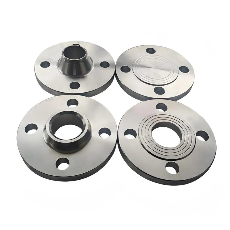
A flange—also referred to as a flange plate or rim—is a component used to connect shafts to one another, or, more commonly, to join the ends of pipes. Flanges are also utilized at the inlet and outlet ports of equipment to facilitate connections between two devices—for instance, the flange on a speed reducer. A "flange connection" or "flanged joint" refers to a detachable joint assembly comprising three interconnected elements—a flange, a gasket, and bolts—that together form a sealed structural unit. In the context of piping systems, a "pipe flange" specifically denotes a flange used for plumbing within the installation; when applied to equipment, it refers to the inlet or outlet flange of that specific device. Flanges feature a series of holes through which bolts are inserted to securely fasten the two flanges together, while a gasket placed between the flanges ensures a leak-proof seal. Flanges are broadly categorized into three types: threaded (screw-in) flanges, welded flanges, and clamp-type flanges. Flanges are invariably used in pairs; threaded flanges are suitable for low-pressure piping applications, whereas welded flanges are required for systems operating at pressures exceeding 4 kilograms per square centimeter. A sealing gasket is inserted between the two flange plates, which are then firmly secured using bolts. The thickness of a flange—as well as the specifications of the bolts used to fasten it—vary depending on the specific pressure rating required for the application. When connecting equipment such as water pumps or valves to piping systems, the corresponding connection points on these devices are often manufactured in the shape of a matching flange; this method of attachment is also referred to as a "flange connection." Generally, any connecting component that utilizes bolts to join and seal the perimeters of two flat surfaces—such as the joints in ventilation ducts—is termed a "flange"; such components may collectively be classified as "flange-type parts." However, since such a connection often constitutes merely a *portion* of a larger device—for instance, the interface between a flange and a water pump—it would be inappropriate to classify the entire water pump itself as a "flange-type part." Conversely, smaller components—such as valves—that feature such flanged interfaces may indeed be appropriately categorized as "flange-type parts."
-:-
For detailed product information, please contact sales.
-:
EN 1.0112 High Manganese Pressure Vessel Carbon Steel Flange Product Information
-:-
For detailed product information, please contact sales.
-:
EN 1.0112 High Manganese Pressure Vessel Carbon Steel Flange Synonyms
-:-
For detailed product information, please contact sales.
-:
EN 1.0112 High Manganese Pressure Vessel Carbon Steel Product Information
-:-
For detailed product information, please contact sales.
-:
# **Technical Datasheet: EN 1.0112 (P235GH) High Manganese Pressure Vessel Carbon Steel**
## **1. PRODUCT OVERVIEW**
**EN 1.0112**, commercially designated **P235GH**, is a **manganese-enhanced, fine-grained carbon steel** specifically engineered for **pressure vessel and boiler applications** at elevated temperatures. Classified under the European pressure equipment standard EN 10028-2, this grade represents the fundamental material choice for welded pressure components operating at **moderate temperatures up to 350°C**. The designation "P" indicates pressure purpose, "235" specifies the minimum yield strength in MPa at room temperature, and "GH" denotes suitability for elevated temperature service (G for gases, H for high temperature).
Unlike general structural steels, P235GH undergoes **strict manufacturing controls** including fine-grain practice, enhanced non-destructive testing, and guaranteed elevated temperature properties. Its optimized **manganese-to-carbon ratio** (typically 3.5:1 to 5:1) provides improved strength and notch toughness compared to plain carbon steels, while maintaining excellent weldability and formability essential for pressure equipment fabrication.
**Key Characteristics:**
- **Pressure Equipment Certified:** Manufactured and tested per EN 10028-2 for pressure applications
- **Elevated Temperature Performance:** Guaranteed minimum yield strength up to 350°C
- **Enhanced Toughness:** Fine-grained structure with improved impact properties
- **Superior Weldability:** Optimized chemistry for pressure vessel welding
- **Strict Quality Controls:** Mandatory ultrasonic testing and enhanced inspection
---
## **2. CHEMICAL COMPOSITION**
**Compliance:** EN 10028-2:2017 - Flat products made of steels for pressure purposes
| Element | Maximum (%) | Typical Range (%) | Metallurgical Function & Control Importance |
|---------|------------|------------------|---------------------------------------------|
| **Carbon (C)** | **0.16** | 0.10-0.14 | Strictly controlled for weldability; lower than structural steels |
| **Manganese (Mn)** | **0.80** | 0.60-0.75 | **Primary strengthener**; enhances elevated temperature properties |
| **Phosphorus (P)** | **0.025** | ≤0.015 | Extremely tight control to prevent temper embrittlement |
| **Sulfur (S)** | **0.015** | ≤0.008 | Ultra-low for improved through-thickness properties |
| **Silicon (Si)** | **0.35** | 0.15-0.30 | Deoxidizer; contributes to high-temperature strength |
| **Aluminum, total (Alt)** | — | **0.020-0.060** | Grain refiner; minimum ensures fine grain structure |
| **Nitrogen (N)** | **0.012** | ≤0.008 | Controlled to prevent strain aging |
| **Copper (Cu)** | 0.30 | ≤0.20 | Residual; strictly limited for weldability |
| **Chromium (Cr)** | 0.30 | ≤0.15 | Residual; limited for weld compatibility |
| **Nickel (Ni)** | 0.30 | ≤0.15 | Residual; limited for cost control |
| **Molybdenum (Mo)** | 0.08 | ≤0.05 | Residual; strictly controlled |
| **Iron (Fe)** | Balance | Balance | Base metal |
**Critical Chemical Parameters for Pressure Applications:**
- **Carbon Equivalent (CEV):** 0.25-0.35% (CEIIW = C + Mn/6)
- **Cracking Sensitivity (Pcm):** 0.16-0.22% (Pcm = C + Si/30 + Mn/20 + Cu/20 + Ni/60 + Cr/20 + Mo/15 + V/10 + 5B)
- **Deoxidation Practice:** Fully aluminum-killed, fine-grained steel
- **Grain Size:** ASTM 5 or finer guaranteed
- **Impurity Control:** Extremely low S and P for improved notch toughness
---
## **3. PHYSICAL & MECHANICAL PROPERTIES**
### **A. Physical Properties (Typical at 20°C):**
- **Density:** 7.85 g/cm³
- **Modulus of Elasticity:** 210 GPa
- **Shear Modulus:** 81 GPa
- **Poisson's Ratio:** 0.30
- **Thermal Conductivity:** 52 W/(m·K)
- **Coefficient of Thermal Expansion:** 11.5 × 10⁻⁶/K (20-100°C)
- **Specific Heat Capacity:** 460 J/(kg·K)
- **Electrical Resistivity:** 0.14 μΩ·m
### **B. Room Temperature Mechanical Properties (EN 10028-2):**
| Property | Symbol | Minimum Value (t ≤ 16 mm) | Test Standard | Notes |
|----------|--------|---------------------------|---------------|-------|
| **Yield Strength** | ReH | **235 MPa** | EN ISO 6892-1 | Upper yield strength |
| **Tensile Strength** | Rm | **360-480 MPa** | EN ISO 6892-1 | Must fall within range |
| **Minimum Elongation** | A | **24%** (t ≤ 3 mm)
**26%** (3 < t ≤ 16 mm) | EN ISO 6892-1 | Longitudinal |
| **Impact Energy** | KV | **27 J at -20°C** (t > 30 mm)
**40 J at 0°C** (t ≤ 30 mm) | EN ISO 148-1 | Option depends on thickness |
### **C. Elevated Temperature Properties:**
**Minimum Yield Strength (Rp0.2) at Temperature:**
| Temperature (°C) | Minimum Yield Strength (MPa) | Reduction Factor | Notes |
|------------------|------------------------------|------------------|-------|
| **50** | 225 | 0.96 | Virtually unchanged |
| **100** | 213 | 0.91 | Minor decrease |
| **150** | 201 | 0.86 | Linear reduction |
| **200** | 189 | 0.80 | Design limit for many applications |
| **250** | 176 | 0.75 | |
| **300** | 164 | 0.70 | Common operating range |
| **350** | 152 | 0.65 | Maximum recommended |
**Creep Properties:**
- **Design Stress Values:** Per EN 13445-2 or ASME Section II-D
- **Creep Limit:** Not applicable (non-creep resistant steel)
- **Maximum Design Temperature:** **350°C** for non-corrosive environments
### **D. Typical Achieved Properties (t = 10-20 mm):**
| Property | Typical Range | Average | Application Significance |
|----------|---------------|---------|--------------------------|
| **Yield Strength (20°C)** | 250-300 MPa | 275 MPa | 15-25% above minimum |
| **Tensile Strength** | 380-440 MPa | 410 MPa | Optimal for pressure design |
| **Elongation** | 28-35% | 32% | Excellent for forming operations |
| **Impact Energy (0°C)** | 50-120 J | 80 J | Substantial toughness margin |
| **Hardness (HB)** | 115-135 | 125 | Suitable for most pressure parts |
| **Fatigue Strength** | 180-220 MPa | 200 MPa | At 2×10⁶ cycles |
---
## **4. FABRICATION & PROCESSING FOR PRESSURE EQUIPMENT**
### **A. Forming Operations:**
- **Cold Forming:** Excellent for dished ends, shells; min bend radius = 1.5t
- **Hot Forming:** 880-950°C maximum; requires normalization after if exceeding 950°C
- **Flanging & Dishing:** Suitable for head forming with proper tooling
- **Springback Compensation:** Approximately 2-3° for cold bending
### **B. Welding Procedures (ASME/AWS/EN 15614 Compliance Required):**
**Critical Requirements for Pressure Vessels:**
- **Welding Procedure Specification (WPS):** Mandatory qualification
- **Preheating:** 50-100°C for t > 25 mm or highly restrained joints
- **Interpass Temperature:** Maximum 250°C
- **Post-Weld Heat Treatment (PWHT):** 580-620°C for t > 35 mm (ASME) or highly restrained welds
**Recommended Welding Consumables:**
| Process | Consumable (EN ISO) | AWS Equivalent | Application Notes |
|---------|---------------------|----------------|-------------------|
| **SMAW** | E 38 0 R C 12 H5 | E7018 | Basic coated for pressure vessels |
| **GTAW** | W 42 2 C G 2Si1 | ER70S-2 | Root passes, critical welds |
| **GMAW** | G 42 4 M G3Si1 | ER70S-6 | General pressure vessel welding |
| **SAW** | S 38 2 + basic flux | F7A2-EM12K | Longitudinal and circumferential seams |
| **FCAW** | T 42 2 P C 1 H5 | E71T-1 | Limited to non-critical applications |
**Welding Quality Requirements:**
- **Radiographic Testing:** 100% for main seams (typically)
- **Ultrasonic Testing:** For thickness > 8 mm
- **Magnetic Particle/Liquid Penetrant:** All accessible welds
- **Weld Repair Limitations:** Strict controls on number/depth of repairs
### **C. Heat Treatment Requirements:**
- **Normalizing:** 890-920°C, air cool - typical delivery condition
- **Stress Relieving:** 580-620°C, 2 hours per 25 mm minimum
- **Post-Forming Heat Treatment:** Required if cold deformation > 5% (ASME) or forming temperature below 550°C
---
## **5. TYPICAL APPLICATIONS**
### **A. Pressure Vessels & Boilers:**
- **Class I Pressure Vessels:** Air receivers, steam drums, water storage tanks
- **Heat Exchangers:** Shells, channels, and tube sheets for low-temperature service
- **Boiler Components:** Economizers, mud drums, deaerators
- **Process Vessels:** Mixing tanks, reaction vessels for non-corrosive media
- **Compressed Gas Storage:** Industrial gas cylinders, buffer vessels
### **B. Industrial Processing Equipment:**
- **Food & Beverage:** Pasteurizers, fermentation tanks, syrup storage
- **Pharmaceutical:** Water-for-injection tanks, clean utility vessels
- **Chemical Processing:** Mild chemical storage, blending vessels
- **Pulp & Paper:** Digester components, pulp storage tanks
### **C. Energy Sector Applications:**
- **Conventional Power:** Feedwater heaters, condensate storage tanks
- **District Heating:** Heat accumulators, distribution system components
- **Renewable Energy:** Thermal storage tanks for solar systems
- **Oil & Gas:** Produced water tanks, low-pressure separators
### **D. Specialized Pressure Equipment:**
- **Cryogenic Applications:** Outer shells for insulated tanks (to -50°C)
- **Hydraulic Systems:** Accumulator shells, hydraulic reservoirs
- **Transportation:** Rail tank car shells for non-hazardous materials
- **Fire Protection:** Sprinkler system tanks, pressure maintenance vessels
**Service Condition Limitations:**
- **Maximum Design Temperature:** 350°C
- **Minimum Design Temperature:** -20°C (lower with impact testing)
- **Pressure Range:** Typically up to 30 bar design pressure
- **Media Compatibility:** Non-corrosive or mildly corrosive with proper lining
---
## **6. INTERNATIONAL STANDARDS & EQUIVALENTS**
### **Primary Designations:**
- **EN Standard:** EN 10028-2:2017
- **Material Number:** 1.0112
- **Steel Name:** P235GH
- **Former Designation:** HII (German AD-Merkblatt)
### **Global Pressure Equipment Equivalents:**
| Country/Standard | Equivalent Grade | Key Comparison Notes |
|-----------------|------------------|----------------------|
| **ISO** | ISO 9328-2: P235GH | Nearly identical specification |
| **USA (ASME)** | SA-516 Gr. 60 | Similar but higher S content allowed |
| **USA (ASME)** | SA-285 Gr. C | Closest equivalent in properties |
| **Germany (DIN)** | DIN EN 10028-2: P235GH | Direct adoption |
| **UK (BS)** | BS 1501-224-490B | Historical equivalent |
| **Japan (JIS)** | JIS G3115: SG255 | Similar but different testing requirements |
| **China (GB)** | GB 713: Q245R | Nearly identical Chinese pressure vessel steel |
| **International** | EN 10216-2: P235GH | For seamless tubes |
### **Comparison within EN 10028 Pressure Steels:**
| Grade | Min Yield (MPa) | Max Temp (°C) | Impact Requirements | Typical Cost Factor |
|-------|----------------|---------------|---------------------|---------------------|
| **P195GH** | 195 | 300 | Less stringent | 0.85 |
| **P235GH** | **235** | **350** | **-20°C / 27J** | **1.00 (Base)** |
| **P265GH** | 265 | 350 | -20°C / 27J | 1.10 |
| **P295GH** | 295 | 350 | -20°C / 27J | 1.20 |
---
## **7. QUALITY ASSURANCE & TESTING**
### **Mandatory Testing (EN 10028-2):**
1. **Tensile Test:** One per plate/coil (transverse for t > 40 mm)
2. **Impact Test:** One set at specified temperature per heat treatment batch
3. **Bend Test:** One transverse test piece
4. **Ultrasonic Testing:** 100% of plate area per EN 10160 Class S2E4 minimum
5. **Visual Inspection:** All surfaces for defects
### **Additional Testing for Critical Applications:**
- **Through-Thickness Testing:** Z15 or Z25 quality if required
- **Drop-Weight Test:** For fracture mechanics analysis
- **High-Temperature Tensile:** For design above 200°C
- **Hydrostatic Testing:** Of finished components per EN 13445
### **Certification Requirements:**
- **EN 10204 3.1 Certificate:** Standard with manufacturer's declaration
- **3.2 Certificate:** Required for CE-marked pressure equipment
- **Traceability:** Complete from melt to finished product
- **Inspection Documents:** Including UT reports, heat treatment charts
### **Non-Destructive Testing Standards:**
- **Ultrasonic:** EN 10160, EN 10306
- **Radiographic:** EN ISO 17636
- **Magnetic Particle:** EN ISO 9934
- **Liquid Penetrant:** EN ISO 3452
---
## **8. DESIGN & SPECIFICATION CONSIDERATIONS**
### **Design Advantages:**
1. **Code Recognition:** Widely accepted in PED, ASME, AD2000 pressure vessel codes
2. **Predictable Properties:** Well-established design allowables
3. **Fabrication Friendly:** Excellent for welding and forming
4. **Economic Efficiency:** Most cost-effective pressure-rated steel
5. **Proven Safety Record:** Extensive history in pressure equipment
### **Design Limitations:**
- **Temperature Limit:** 350°C maximum for pressure parts
- **Corrosion Resistance:** Limited to non-corrosive environments
- **Thickness Restrictions:** Properties guaranteed to 100 mm maximum
- **Not for Hydrogen Service:** Not suitable for wet H₂S or hydrogen embrittlement service
### **Specification Best Practices:**
```plaintext
EN 10028-2 P235GH+N
Thickness: [specify with tolerance]
Delivery Condition: Normalized (N)
Supplementary Requirements:
- Ultrasonic testing EN 10160 Class S3E4
- Impact testing at -20°C with test location at 1/4 thickness
- Maximum CEV: 0.35%
- Certification: EN 10204 3.2
- Marking: Heat number, standard, grade on each piece
```
### **Pressure Design Rules:**
- **Design Formulas:** Per EN 13445-3 or ASME Section VIII Div. 1
- **Joint Efficiency:** 0.85-1.00 depending on joint type and examination
- **Corrosion Allowance:** Typically 1-3 mm added to calculated thickness
- **Minimum Thickness:** Often governed by handling/stiffness, not pressure
---
## **9. ENVIRONMENTAL & SAFETY CONSIDERATIONS**
### **Corrosion Protection:**
- **Internal Lining:** Rubber, glass, or epoxy for corrosive service
- **External Coating:** Epoxy or polyurethane paint systems
- **Cathodic Protection:** For buried or submerged vessels
- **Galvanizing:** Generally not recommended for pressure parts
### **Safety Factors:**
- **Design Factor:** Typically 1.5 on tensile strength (EN 13445)
- **Hydrostatic Test Pressure:** 1.43 × design pressure (EN) or 1.3 × (ASME)
- **Pressure Relief:** Required per EN 13445 or ASME Section VIII
- **Inspection Intervals:** Regular in-service inspection required
### **Environmental Compliance:**
- **PED Compliance:** Essential for European market (2014/68/EU)
- **ASME Stamp:** Required for US and many international projects
- **Environmental Impact:** Lower than alloy steels due to simpler chemistry
- **Recyclability:** >95% at end of life
---
## **10. TECHNICAL SUMMARY**
**EN 1.0112 (P235GH)** represents the **foundation grade** for pressure equipment construction, offering an optimal balance of **strength, weldability, formability, and cost-effectiveness** for moderate temperature and pressure applications. Its strict manufacturing controls and guaranteed properties make it the **default choice** for a wide range of pressure vessels, boilers, and heat exchangers operating below 350°C.
**Market Position & Usage:** P235GH accounts for approximately 40-50% of all carbon steel pressure vessel plate in Europe, reflecting its status as the workhorse material for:
- Industrial pressure vessels
- Low to medium-pressure boilers
- Storage tanks with pressure rating
- Heat exchanger shells and channels
**Industry Trends:** Increasing emphasis on energy efficiency and safety regulations continues to drive demand for certified pressure vessel steels like P235GH. The trend toward standardized, modular pressure equipment favors materials with well-established fabrication procedures and code acceptance.
**Selection Decision Framework:**
- **For temperatures 0-350°C and pressures to ~30 bar:** P235GH is typically the most economical choice
- **For temperatures >350°C:** Consider P265GH or low-alloy steels
- **For highly corrosive environments:** Consider stainless steels or clad materials
- **For severe cyclic service:** Evaluate fatigue properties and consider higher grades
**Final Recommendation:** P235GH should be specified as the default material for carbon steel pressure equipment operating within its temperature and pressure limits. Its extensive code recognition, predictable behavior during fabrication, and favorable economics make it the rational first choice for engineers designing pressure-containing components.
---
**Important Notice:** This technical datasheet provides general information. For pressure equipment design:
1. Always consult the latest editions of applicable pressure vessel codes (EN 13445, ASME Section VIII, etc.)
2. Engage qualified pressure vessel engineers for design and fabrication oversight
3. Review actual mill certificates and verify they meet project requirements
4. Consider specific service conditions including media, temperature cycles, and pressure fluctuations
5. Ensure fabrication is performed by certified pressure vessel workshops
Pressure equipment design and fabrication require specialized expertise and certification. Always work with qualified personnel and organizations holding appropriate pressure equipment certifications.
-:-
For detailed product information, please contact sales.
-:
EN 1.0112 High Manganese Pressure Vessel Carbon Steel Specification
Dimensions
Size:
Diameter 20-1000 mm Length <5789 mm
Size:We can customized as required
Standard:
Per your request or drawing
We can customized as required
Properties(Theoretical)
Chemical Composition
-:-
For detailed product information, please contact sales.
-:
EN 1.0112 High Manganese Pressure Vessel Carbon Steel Properties
-:-
For detailed product information, please contact sales.
-:
Applications of EN 1.0112 High Manganese Pressure Vessel Carbon Steel Flange
-:-
For detailed product information, please contact sales.
-:
Chemical Identifiers EN 1.0112 High Manganese Pressure Vessel Carbon Steel Flange
-:-
For detailed product information, please contact sales.
-:
Packing of EN 1.0112 High Manganese Pressure Vessel Carbon Steel Flange
-:-
For detailed product information, please contact sales.
-:
Standard Packing:
-:-
For detailed product information, please contact sales.
-:
Typical bulk packaging includes palletized plastic 5 gallon/25 kg. pails, fiber and Steel Flange drums to 1 ton super sacks in full container (FCL) or truck load (T/L) quantities. Research and sample quantities and hygroscopic, oxidizing or other air sensitive materials may be packaged under argon or vacuum. Solutions are packaged in polypropylene, plastic or glass jars up to palletized 2260 gallon liquid totes Special package is available on request. E FORUs’ is carefully handled to minimize damage during storage and transportation and to preserve the quality of our products in their original condition


")
