1,We Manufacturing processes are primarily classified into four types:
1:Forging,
2:Casting,
3:Cutting,
4:Rolling.
2,We can manufacture in accordance with these standards.
Standards:
GB Series (Chinese Standards), JB Series (Machinery Standards), HG Series (Chemical Industry Standards), ASME B16.5 (American Standards), BS4504 (British Standards), DIN (German Standards), and JIS (Japanese Standards).
Internationally, there are two primary systems of pipe flange standards: the European system, represented by the German DIN standards (including those of the former Soviet Union), and the American system, represented by the US ANSI pipe flange standards. Other common standards include: the Chinese Ministry of Machinery Industry standards (JB series), the Ministry of Chemical Industry standards (HG series), the Chinese National Standard *GB/T 9112–9124-2010 Steel Pipe Flanges*, as well as US standards (ASME B16.5), British standards (BS4504), German standards (DIN), Japanese standards (JIS), and marine standards (CBM), among others.
The nominal pressure ratings for the PN series are designated by "PN" and comprise the following nine levels: PN2.5, PN6, PN10, PN16, PN25, PN40, PN63, PN100, and PN160.
The nominal pressure ratings for the Class series are designated by "Class" and comprise the following six levels: Class150, Class300, Class600, Class900, Class1500, and Class2500.
Flange Classification
1. **According to Chemical Industry Standards:** Flanges are classified as follows:
Plate Flat Welding Flange (PL), Necked Flat Welding Flange (SO), Necked Butt Welding Flange (WN), Integral Flange (IF), Socket Welding Flange (SW), Threaded Flange (Th), Butt Welding Ring Loose Flange (PJ/SE), Blind Flange (BL), Flat Welding Ring Loose Flange (PJ/PJ), and Lined Blind Flange (BL(s)).
2. **According to Petrochemical (SH) Industry Standards:** Flanges are classified as follows:
Threaded Flange (PL), Butt Welding Flange (WN), Flat Welding Flange (SO), Socket Welding Flange (SW), Loose Flange (LJ), and Blind Flange (no specific designation).
3. **According to Machinery (JB) Industry Standards:** Flanges are classified as follows:
Integral Flange, Butt Welding Flange, Plate Flat Welding Flange, Butt Welding Ring Plate Loose Flange, Flat Welding Ring Plate Loose Flange, Lap Joint Ring Plate Loose Flange, and Blind Flange.
4. **According to Connection Method/Type:** Flanges are classified as follows:
Plate Flat Welding Flange, Necked Flat Welding Flange, Necked Butt Welding Flange, Socket Welding Flange, Threaded Flange, Blind Flange, Necked Butt Welding Ring Loose Flange, Flat Welding Ring Loose Flange, Ring-Type Joint (RTJ) Flange and Blind Flange, Large-Diameter Plate Flange, Large-Diameter High-Neck Flange, Figure-8 Blind Plate, Butt Welding Ring Loose Flange, etc.
5. **According to the Component Being Connected:** Flanges can be classified into Vessel Flanges and Pipe Flanges.
6. **According to Structural Type:** Flanges include Integral Flanges, Threaded Flanges, Flat Welding Flanges, Butt Welding Flanges, Lap Joint (Loose/Swivel) Flanges, and Blind Flanges.
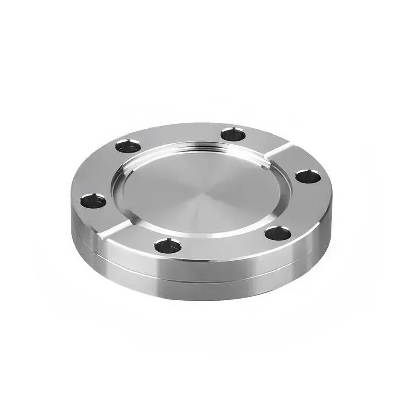
A flange—also referred to as a flange plate or rim—is a component used to connect shafts to one another, or, more commonly, to join the ends of pipes. Flanges are also utilized at the inlet and outlet ports of equipment to facilitate connections between two devices—for instance, the flange on a speed reducer. A "flange connection" or "flanged joint" refers to a detachable joint assembly comprising three interconnected elements—a flange, a gasket, and bolts—that together form a sealed structural unit. In the context of piping systems, a "pipe flange" specifically denotes a flange used for plumbing within the installation; when applied to equipment, it refers to the inlet or outlet flange of that specific device. Flanges feature a series of holes through which bolts are inserted to securely fasten the two flanges together, while a gasket placed between the flanges ensures a leak-proof seal. Flanges are broadly categorized into three types: threaded (screw-in) flanges, welded flanges, and clamp-type flanges. Flanges are invariably used in pairs; threaded flanges are suitable for low-pressure piping applications, whereas welded flanges are required for systems operating at pressures exceeding 4 kilograms per square centimeter. A sealing gasket is inserted between the two flange plates, which are then firmly secured using bolts. The thickness of a flange—as well as the specifications of the bolts used to fasten it—vary depending on the specific pressure rating required for the application. When connecting equipment such as water pumps or valves to piping systems, the corresponding connection points on these devices are often manufactured in the shape of a matching flange; this method of attachment is also referred to as a "flange connection." Generally, any connecting component that utilizes bolts to join and seal the perimeters of two flat surfaces—such as the joints in ventilation ducts—is termed a "flange"; such components may collectively be classified as "flange-type parts." However, since such a connection often constitutes merely a *portion* of a larger device—for instance, the interface between a flange and a water pump—it would be inappropriate to classify the entire water pump itself as a "flange-type part." Conversely, smaller components—such as valves—that feature such flanged interfaces may indeed be appropriately categorized as "flange-type parts."
-:-
For detailed product information, please contact sales.
-:
AISI 8740H Steel Flange, oil quenched 830°C (1525°F), 540°C (1000°F) temper Product Information
-:-
For detailed product information, please contact sales.
-:
AISI 8740H Steel Flange, oil quenched 830°C (1525°F), 540°C (1000°F) temper Synonyms
-:-
For detailed product information, please contact sales.
-:
AISI 8740H Steel, oil quenched 830°C (1525°F), 540°C (1000°F) temper Product Information
-:-
For detailed product information, please contact sales.
-:
# **Technical Specification: AISI 8740H Steel – Oil Quenched and Tempered**
## **1. PRODUCT IDENTIFICATION & OVERVIEW**
### **Basic Information**
| **Property** | **Specification** |
|--------------|-------------------|
| **Standard Designation** | AISI 8740H / SAE 8740H |
| **UNS Number** | G87401 |
| **Material Type** | Hardenability-Banded Ni-Cr-Mo Alloy Steel |
| **Heat Treatment** | Oil Quenched at 830°C (1525°F) + Tempered at 540°C (1000°F) |
| **Key Feature** | "H" suffix indicates controlled hardenability per SAE J1268/ASTM A304 |
| **Material Condition** | Quenched and tempered (heat treated) |
### **International Standard Equivalents**
| **Standard** | **Designation** | **Notes** |
|--------------|-----------------|-----------|
| **ASTM (USA)** | A304 Grade 8740H | Hardenability specification |
| **AMS (Aerospace)** | AMS 6322 | Q&T condition for aerospace applications |
| **DIN (Germany)** | 1.6546H / 41CrMo4H | QT condition, Hardenability certified |
| **EN (Europe)** | 1.7225H / 42CrMo4H QT | Quenched and tempered condition |
| **JIS (Japan)** | SCM440H QT | Japanese H-grade equivalent, heat treated |
| **ISO** | 683-1 41CrMo4H QT | International standardization |
| **GB (China)** | 42CrMoH QT | Chinese H-grade standard, heat treated |
---
## **2. CHEMICAL COMPOSITION (Weight %)**
AISI 8740H chemistry is controlled to ensure consistent hardenability within specified bands, with this specific heat treatment optimizing the balance of strength and toughness.
### **Standard Composition Ranges**
| **Element** | **Minimum (%)** | **Maximum (%)** | **Typical (%)** | **Metallurgical Function** |
|-------------|-----------------|-----------------|-----------------|---------------------------|
| **Carbon (C)** | 0.37 | 0.44 | 0.40-0.42 | Primary strength and hardenability control |
| **Manganese (Mn)** | 0.65 | 1.10 | 0.80-0.95 | Austenite stabilizer, improves hardenability |
| **Silicon (Si)** | 0.15 | 0.35 | 0.20-0.30 | Deoxidizer, solid solution strengthener |
| **Chromium (Cr)** | 0.35 | 0.65 | 0.45-0.55 | Forms carbides, improves wear resistance |
| **Nickel (Ni)** | 0.35 | 0.75 | 0.45-0.65 | **Critical for toughness**, refines grain |
| **Molybdenum (Mo)** | 0.15 | 0.30 | 0.20-0.25 | Prevents temper embrittlement, deep hardening |
| **Phosphorus (P)** | - | 0.025 | ≤0.020 | Impurity control (minimized for toughness) |
| **Sulfur (S)** | - | 0.025 | 0.010-0.020 | Machinability improvement |
| **Iron (Fe)** | Balance | - | - | Matrix element |
### **Calculated Parameters**
- **Carbon Equivalent (CE):** 0.78-0.85 (CE = C + Mn/6 + (Cr+Mo+V)/5 + (Ni+Cu)/15)
- **Ideal Critical Diameter (Dᵢ):** 95-135 mm (3.7-5.3 inches) in oil quench
- **Hardenability Index:** Excellent through-medium section capability
**Special Note:** The "H" designation ensures consistent heat treatment response across production batches through guaranteed hardenability bands rather than strict chemical composition limits.
---
## **3. HEAT TREATMENT PROCESS**
### **Austenitizing and Quenching**
- **Austenitizing Temperature:** 830°C ± 10°C (1525°F ± 20°F)
- **Soaking Time:** 20-30 minutes per 25 mm (1 inch) of thickness
- **Quenching Medium:** Fast oil (ISO VG 68 or equivalent)
- **Quenching Temperature:** Oil temperature 40-80°C (100-175°F)
- **Agitation:** Moderate to high for optimal heat transfer
- **Resulting Structure:** As-quenched martensite (hard and brittle)
### **Tempering Process**
- **Tempering Temperature:** 540°C ± 10°C (1000°F ± 20°F)
- **Tempering Time:** 1-2 hours per 25 mm (1 inch), minimum 2 hours
- **Cooling Method:** Air cooling to ambient temperature
- **Atmosphere:** Neutral or protective atmosphere
- **Final Structure:** Tempered martensite (fine carbides in ferrite matrix)
### **Metallurgical Transformation**
1. **Austenitizing:** Complete dissolution of carbides, homogeneous austenite
2. **Quenching:** Martensitic transformation (Ms ≈ 345°C, Mf ≈ 195°C)
3. **Tempering:** Stage 3-4 tempering (ε-carbide → cementite precipitation)
4. **Final Structure:** Fine tempered martensite with optimal strength-toughness balance
---
## **4. MECHANICAL PROPERTIES**
### **Typical Properties (Section ≤ 25mm / 1 inch)**
| **Property** | **Value Range** | **Test Standard** | **Notes** |
|--------------|----------------|-------------------|-----------|
| **Hardness** | 32-38 HRC (302-352 HBW) | ASTM E18/E10 | Primary quality control parameter |
| **Tensile Strength** | 1050-1200 MPa (152-174 ksi) | ASTM E8 | High strength with good ductility |
| **Yield Strength (0.2%)** | 950-1100 MPa (138-160 ksi) | ASTM E8 | Excellent yield-to-tensile ratio |
| **Elongation (50mm)** | 14-18% | ASTM E8 | Good ductility for this strength level |
| **Reduction of Area** | 45-55% | ASTM E8 | Indicates good toughness |
| **Modulus of Elasticity** | 205-210 GPa (29,700-30,500 ksi) | ASTM E111 | |
| **Charpy V-Notch Impact** | 40-60 J (30-44 ft·lb) @ 21°C | ASTM E23 | **Excellent toughness** |
| **Fatigue Strength (Rotating)** | 500-600 MPa | ASTM E466 | Very good fatigue resistance |
| **Shear Strength** | 700-800 MPa | ASTM B769 | |
### **Properties vs. Section Size**
| **Section Diameter** | **Surface Hardness (HRC)** | **Core Hardness (HRC)** | **Tensile Strength (MPa)** | **Impact Toughness (J)** |
|----------------------|----------------------------|-------------------------|----------------------------|--------------------------|
| ≤25 mm (1") | 34-38 | 34-38 | 1100-1200 | 45-60 |
| 25-50 mm (1-2") | 33-37 | 32-36 | 1050-1150 | 40-55 |
| 50-75 mm (2-3") | 32-36 | 30-34 | 1000-1100 | 35-50 |
| 75-100 mm (3-4") | 31-35 | 28-32 | 950-1050 | 30-45 |
### **Temperature-Dependent Properties**
| **Temperature** | **Tensile Strength** | **Yield Strength** | **Impact Toughness** |
|-----------------|----------------------|-------------------|----------------------|
| -40°C (-40°F) | 1150-1250 MPa | 1050-1150 MPa | 25-40 J |
| 21°C (70°F) | 1050-1200 MPa | 950-1100 MPa | 40-60 J |
| 100°C (212°F) | 1000-1150 MPa | 900-1050 MPa | 50-70 J |
| 200°C (392°F) | 900-1050 MPa | 800-950 MPa | 55-75 J |
---
## **5. PHYSICAL PROPERTIES**
| **Property** | **Value @ 20°C (68°F)** | **Test Method** | **Notes** |
|--------------|-------------------------|-----------------|-----------|
| **Density** | 7.85 g/cm³ (0.284 lb/in³) | ASTM B311 | |
| **Thermal Conductivity** | 42.0 W/m·K | ASTM E1461 | After tempering |
| **Specific Heat Capacity** | 480 J/kg·K | ASTM E1269 | |
| **Coefficient of Thermal Expansion** | 12.5 × 10⁻⁶/K (20-200°C) | ASTM E228 | |
| **Electrical Resistivity** | 0.24 μΩ·m | ASTM B193 | |
| **Magnetic Properties** | Ferromagnetic | - | Curie temp: ~770°C |
| **Acoustic Velocity** | 5900 m/s (longitudinal) | Ultrasonic | For NDT reference |
---
## **6. HARDENABILITY CHARACTERISTICS**
### **Jominy End-Quench Test Results (As-Quenched)**
| **Distance from Quenched End** | **Hardness Range (HRC)** | **After 540°C Temper (HRC)** |
|--------------------------------|--------------------------|-------------------------------|
| 1/16 inch (1.6 mm) | 52-57 | 38-42 |
| 1/4 inch (6.4 mm) | 49-53 | 36-40 |
| 1/2 inch (12.7 mm) | 43-48 | 34-38 |
| 1 inch (25.4 mm) | 35-40 | 32-36 |
| 2 inches (50.8 mm) | 29-34 | 28-32 |
| 3 inches (76.2 mm) | 26-30 | 25-28 |
### **Section Hardness Penetration**
| **Distance from Surface** | **75mm Diameter Bar (HRC)** | **100mm Diameter Bar (HRC)** | **150mm Diameter Bar (HRC)** |
|---------------------------|------------------------------|-------------------------------|-------------------------------|
| Surface | 34-36 | 33-35 | 31-33 |
| 1/4 Radius | 33-35 | 32-34 | 29-31 |
| Center | 32-34 | 30-32 | 27-29 |
### **Ideal Critical Diameters for This Treatment**
| **Criterion** | **Oil Quench (Dᵢ)** | **Water Quench (Dᵢ)** | **Polymer Quench (Dᵢ)** |
|---------------|---------------------|------------------------|--------------------------|
| 50% Martensite | 100-120 mm | 130-150 mm | 85-100 mm |
| 90% Martensite | 75-90 mm | 100-120 mm | 60-75 mm |
| 95% Martensite | 65-80 mm | 85-105 mm | 50-65 mm |
---
## **7. MICROSTRUCTURAL CHARACTERISTICS**
### **As-Quenched Condition (Before Tempering)**
- **Primary Phase:** Lath martensite with retained austenite (<5%)
- **Prior Austenite Grain Size:** ASTM 6-7
- **Martensite Plate Size:** 0.2-0.5 μm width
- **Retained Austenite:** Typically 3-5% at room temperature
### **After Tempering at 540°C**
- **Matrix:** Tempered martensite (ferrite with fine carbides)
- **Carbide Types:** ε-carbide transition to cementite (Fe₃C)
- **Carbide Size:** 10-50 nm, uniformly dispersed
- **Grain Structure:** Fine, equiaxed ferrite grains
- **Precipitation:** Mo₂C and Cr₇C₃ carbides beginning to form
### **Microstructural Stability**
- **Tempering Parameter (Hollomon-Jaffe):** P = T(log t + 20) ≈ 18,500
- **Resistance to Overtempering:** Good up to 600°C (1110°F)
- **Temper Embrittlement Range:** 375-575°C (707-1067°F) - Mo addition minimizes risk
---
## **8. PERFORMANCE CHARACTERISTICS**
### **Fatigue Properties**
- **Endurance Limit (Rotating Bending):** 500-550 MPa (10⁷ cycles)
- **Fatigue Ratio (σₑ/σᵤ):** 0.45-0.50
- **Notch Sensitivity:** Moderate (q ≈ 0.7-0.8)
- **Surface Finish Factor:** Ground/polished: 0.9, Machined: 0.8, As-forged: 0.7
### **Fracture Toughness**
- **K₁c (Plane Strain Fracture Toughness):** 80-100 MPa√m
- **CTOD (Crack Tip Opening Displacement):** 0.15-0.25 mm
- **Transition Temperature:** Typically below -20°C (-4°F)
### **Wear Resistance**
- **Abrasive Wear:** Good (superior to normalized condition)
- **Adhesive Wear:** Very good with proper lubrication
- **Contact Fatigue Strength:** Excellent for gear applications
---
## **9. PROCESSING CHARACTERISTICS**
### **Machinability in Heat Treated Condition**
- **Machinability Rating:** 40-50% (relative to annealed 1212 = 100%)
- **Recommended Cutting Conditions:**
- **Cutting Speed:** 25-40 m/min (80-130 ft/min) for turning
- **Feed Rate:** 0.10-0.20 mm/rev (0.004-0.008 in/rev)
- **Depth of Cut:** Up to 3 mm (0.120 in)
- **Tool Materials:** Cermet or coated carbide grades (P20-P30)
- **Coolant:** Required, preferably high-pressure coolant
- **Grindability:** Good with proper wheel selection
### **Weldability**
- **Carbon Equivalent (IIW):** 0.78-0.85
- **Weldability Rating:** Poor (requires special procedures)
- **Preheat Temperature:** 200-300°C (400-570°F)
- **Post-Weld Heat Treatment:** Mandatory (temper at 540-600°C)
- **Recommended Processes:** GTAW with matching filler (ER80S-D2)
- **Heat Affected Zone (HAZ):** Hardness up to 50 HRC, requires tempering
### **Finishing Operations**
- **Grinding:** White aluminum oxide wheels, 46-60 grit
- **Polishing:** Can achieve Ra 0.2 μm (8 μin) with proper sequence
- **Plating:** Chrome, nickel, or zinc plating compatible
- **Coating:** Nitriding, PVD, DLC coatings possible with surface preparation
---
## **10. TYPICAL APPLICATIONS**
### **Aerospace & Defense**
- **Aircraft Landing Gear:** Axles, pistons, torque links
- **Helicopter Components:** Rotor hubs, drive shafts, gearbox components
- **Missile Systems:** Launch rails, guidance system components
- **Military Vehicle Parts:** Track links, suspension arms, weapon mounts
- **Jet Engine Components:** Mounts, brackets, accessory drive parts
### **Automotive & Heavy Vehicles**
- **Performance Crankshafts:** Racing and high-performance engines
- **Transmission Components:** Gears, synchronizers, shift forks
- **Drivetrain Parts:** Axle shafts, differential gears, drive shafts
- **Steering Components:** Pitman arms, idler arms, tie rods
- **Suspension Parts:** Control arms, torsion bars, spring perches
### **Industrial Machinery**
- **Gear Manufacturing:** High-load gears for industrial drives
- **Machine Tool Components:** Spindles, arbors, tool holders
- **Hydraulic Equipment:** Pump shafts, piston rods, valve stems
- **Mining Equipment:** Crusher jaws, drill bits, conveyor components
- **Construction Machinery:** Excavator pins, boom arms, bucket linkages
### **Oil & Gas Industry**
- **Drill String Components:** Tool joints, subs, stabilizers
- **Downhole Tools:** Mills, reamers, fishing tools
- **Wellhead Equipment:** Valve stems, gates, operators
- **Pipeline Components:** High-pressure fittings, flange studs
### **Power Generation**
- **Turbine Components:** Shafts, blades, disks for steam turbines
- **Generator Parts:** Rotor shafts, retaining rings
- **Nuclear Components:** Control rod drive mechanisms
- **Hydroelectric Equipment:** Turbine shafts, wicket gate components
### **Additional High-Performance Applications**
- **Marine Components:** Propeller shafts, rudder stocks, deck machinery
- **Agricultural Equipment:** Gear boxes, PTO shafts, implement hubs
- **Railway Components:** Axles, wheels, coupling devices
- **Heavy Fabrications:** Crane hooks, lifting eyes, structural pins
---
## **11. QUALITY ASSURANCE & TESTING**
### **Standard Testing Requirements**
1. **Chemical Analysis:** Per heat/lot (ASTM A751)
2. **Hardenability Test:** Jominy end-quench (ASTM A255)
3. **Mechanical Testing:** Tensile, hardness, impact (ASTM A370)
4. **Microstructure Evaluation:** ASTM E112, E45
5. **Macroetch Test:** For internal soundness (ASTM E381)
### **Specialized Testing**
- **Fatigue Testing:** Rotating beam or axial fatigue (ASTM E466)
- **Fracture Toughness:** K₁c or CTOD testing (ASTM E399, E1290)
- **Residual Stress Analysis:** X-ray diffraction or hole drilling method
- **Decarburization Check:** Microhardness traverse (ASTM E1077)
### **Nondestructive Testing**
- **Ultrasonic Testing:** ASTM A388 for internal defects
- **Magnetic Particle Inspection:** ASTM E709 for surface cracks
- **Dye Penetrant Inspection:** ASTM E165 for surface defects
- **Eddy Current Testing:** For surface and near-surface flaws
### **Certification Levels**
| **Grade** | **Testing Requirements** | **Documentation** | **Typical Applications** |
|-----------|--------------------------|-------------------|--------------------------|
| **Standard Q&T** | Chemistry, hardness, tensile | MTR 3.1 | General engineering |
| **Aircraft Quality** | Full mechanical + impact + NDT | AMS cert + full traceability | Aerospace components |
| **Nuclear Quality** | Enhanced testing + Charpy curves | N-stamp certification | Nuclear applications |
| **Customer-Specific** | Per drawing requirements | Custom certification | Critical applications |
---
## **12. DESIGN CONSIDERATIONS**
### **Advantages of This Heat Treatment**
1. **Optimal Strength-Toughness Balance:** 540°C temper provides excellent combination
2. **Predictable Performance:** H-grade ensures consistent properties
3. **Good Fatigue Resistance:** Suitable for cyclic loading applications
4. **Wide Application Range:** Versatile for various engineering applications
5. **Cost-Effective Performance:** Provides premium properties at reasonable cost
### **Design Guidelines**
- **Section Size Limitations:** Maximum effective hardening depth ~75mm (3 inches)
- **Stress Concentrations:** Use generous fillet radii (minimum R5 mm)
- **Surface Finish:** Specify grinding/polishing for fatigue-critical applications
- **Corrosion Protection:** Require plating/coating for corrosive environments
- **Dimensional Tolerances:** Allow for heat treatment distortion (0.1-0.3%)
### **Failure Prevention**
- **Avoid Sharp Corners:** Prevent stress concentrations
- **Proper Heat Treatment:** Ensure full transformation and tempering
- **Surface Protection:** Prevent stress corrosion cracking
- **Regular Inspection:** Monitor for fatigue cracks in service
---
## **13. COMPARATIVE ANALYSIS**
### **vs. Other Tempering Temperatures**
| **Tempering Temperature** | **Hardness (HRC)** | **Tensile Strength (MPa)** | **Impact Toughness (J)** | **Best For** |
|---------------------------|-------------------|----------------------------|--------------------------|--------------|
| **200°C (400°F)** | 48-52 | 1450-1650 | 15-25 | Maximum hardness, wear parts |
| **400°C (750°F)** | 38-42 | 1200-1350 | 30-40 | High strength, moderate toughness |
| **540°C (1000°F)** | 32-38 | 1050-1200 | 40-60 | **Optimal balance** |
| **650°C (1200°F)** | 25-30 | 850-950 | 60-80 | Maximum toughness |
### **vs. Similar Grades**
| **Grade** | **Ni Content** | **Toughness** | **Cost** | **Best Application** |
|-----------|---------------|---------------|----------|----------------------|
| **4140H** | None | Good | Lower | General purpose |
| **4340H** | 1.65-2.00% | Excellent | Higher | Ultra-high toughness |
| **8740H** | 0.35-0.75% | Very Good | Moderate | **Optimal balance** |
| **9840H** | 0.85-1.15% | Excellent | Higher | Critical aerospace |
---
## **14. ORDERING INFORMATION**
### **Standard Order Specifications**
```plaintext
Material: AISI 8740H, Oil Quenched and Tempered
Heat Treatment: 830°C Oil Quench + 540°C Temper
Hardness Requirement: 34-36 HRC (specify range)
Certification: MTR 3.1 with mechanical test results
Tolerances: Per ASTM A29 or drawing specifications
```
### **Critical Ordering Parameters**
1. **Mechanical Properties:** Specify required tensile, yield, hardness ranges
2. **Hardenability:** Jominy band requirements if different from standard
3. **Testing Requirements:** Additional tests beyond standard
4. **Surface Condition:** As-heat treated, ground, or machined
5. **Certification Level:** Standard, aircraft, or nuclear quality
6. **Traceability:** Heat number tracking requirements
### **Lead Times & Minimums**
- **Standard Treatment:** 6-8 weeks production time
- **Special Testing:** Additional 2-4 weeks
- **Minimum Order:** Typically 1000 kg (2200 lb) for standard treatment
- **Emergency Service:** Available at premium for critical needs
---
## **15. TECHNICAL SUPPORT & RESOURCES**
### **Reference Standards**
- **SAE J404:** Chemical Compositions of SAE Alloy Steels
- **SAE J1268:** Hardenability Bands for Alloy H-Steels
- **ASTM A304:** Alloy Steel Bars Subject to End-Quench Hardenability
- **ASTM A29:** General Requirements for Steel Bars
- **AMS 6322:** Steel Bars, Alloy, 8740H, Q&T
### **Industry Specifications**
- **Aerospace:** AMS, MIL, NAS, and customer-specific standards
- **Automotive:** SAE, AIAG, and OEM specifications
- **Oil & Gas:** API, NACE, and industry standards
- **Power Generation:** ASME, ASTM, and utility standards
### **Technical Services**
- **Heat Treatment Consultation:** Optimal cycle development
- **Failure Analysis:** Metallurgical investigation services
- **Process Optimization:** Manufacturing efficiency improvement
- **Quality System Support:** Certification and audit assistance
- **Material Selection:** Application-specific recommendations
---
**Disclaimer:** This technical data sheet provides typical values and characteristics for informational purposes. Actual properties may vary based on specific manufacturing processes, heat treatment parameters, section size, cooling rates, and other factors. The information is based on standard industry practices and may not cover all possible variations or applications. For critical applications, conduct appropriate testing, consult with qualified materials engineers, and perform thorough validation. Always refer to the latest edition of relevant standards and specifications, and verify all information with the material supplier before making design or procurement decisions. The manufacturer assumes no liability for applications or use of this material beyond its intended purpose as described in applicable standards.
-:-
For detailed product information, please contact sales.
-:
AISI 8740H Steel, oil quenched 830°C (1525°F), 540°C (1000°F) temper Specification
Dimensions
Size:
Diameter 20-1000 mm Length <6388 mm
Size:We can customized as required
Standard:
Per your request or drawing
We can customized as required
Properties(Theoretical)
Chemical Composition
-:-
For detailed product information, please contact sales.
-:
AISI 8740H Steel, oil quenched 830°C (1525°F), 540°C (1000°F) temper Properties
-:-
For detailed product information, please contact sales.
-:
Applications of AISI 8740H Steel Flange, oil quenched 830°C (1525°F), 540°C (1000°F) temper
-:-
For detailed product information, please contact sales.
-:
Chemical Identifiers AISI 8740H Steel Flange, oil quenched 830°C (1525°F), 540°C (1000°F) temper
-:-
For detailed product information, please contact sales.
-:
Packing of AISI 8740H Steel Flange, oil quenched 830°C (1525°F), 540°C (1000°F) temper
-:-
For detailed product information, please contact sales.
-:
Standard Packing:
-:-
For detailed product information, please contact sales.
-:
Typical bulk packaging includes palletized plastic 5 gallon/25 kg. pails, fiber and Steel Flange drums to 1 ton super sacks in full container (FCL) or truck load (T/L) quantities. Research and sample quantities and hygroscopic, oxidizing or other air sensitive materials may be packaged under argon or vacuum. Solutions are packaged in polypropylene, plastic or glass jars up to palletized 2859 gallon liquid totes Special package is available on request. E FORUs’ is carefully handled to minimize damage during storage and transportation and to preserve the quality of our products in their original condition