1,We Manufacturing processes are primarily classified into four types:
1:Forging,
2:Casting,
3:Cutting,
4:Rolling.
2,We can manufacture in accordance with these standards.
Standards:
GB Series (Chinese Standards), JB Series (Machinery Standards), HG Series (Chemical Industry Standards), ASME B16.5 (American Standards), BS4504 (British Standards), DIN (German Standards), and JIS (Japanese Standards).
Internationally, there are two primary systems of pipe flange standards: the European system, represented by the German DIN standards (including those of the former Soviet Union), and the American system, represented by the US ANSI pipe flange standards. Other common standards include: the Chinese Ministry of Machinery Industry standards (JB series), the Ministry of Chemical Industry standards (HG series), the Chinese National Standard *GB/T 9112–9124-2010 Steel Pipe Flanges*, as well as US standards (ASME B16.5), British standards (BS4504), German standards (DIN), Japanese standards (JIS), and marine standards (CBM), among others.
The nominal pressure ratings for the PN series are designated by "PN" and comprise the following nine levels: PN2.5, PN6, PN10, PN16, PN25, PN40, PN63, PN100, and PN160.
The nominal pressure ratings for the Class series are designated by "Class" and comprise the following six levels: Class150, Class300, Class600, Class900, Class1500, and Class2500.
Flange Classification
1. **According to Chemical Industry Standards:** Flanges are classified as follows:
Plate Flat Welding Flange (PL), Necked Flat Welding Flange (SO), Necked Butt Welding Flange (WN), Integral Flange (IF), Socket Welding Flange (SW), Threaded Flange (Th), Butt Welding Ring Loose Flange (PJ/SE), Blind Flange (BL), Flat Welding Ring Loose Flange (PJ/PJ), and Lined Blind Flange (BL(s)).
2. **According to Petrochemical (SH) Industry Standards:** Flanges are classified as follows:
Threaded Flange (PL), Butt Welding Flange (WN), Flat Welding Flange (SO), Socket Welding Flange (SW), Loose Flange (LJ), and Blind Flange (no specific designation).
3. **According to Machinery (JB) Industry Standards:** Flanges are classified as follows:
Integral Flange, Butt Welding Flange, Plate Flat Welding Flange, Butt Welding Ring Plate Loose Flange, Flat Welding Ring Plate Loose Flange, Lap Joint Ring Plate Loose Flange, and Blind Flange.
4. **According to Connection Method/Type:** Flanges are classified as follows:
Plate Flat Welding Flange, Necked Flat Welding Flange, Necked Butt Welding Flange, Socket Welding Flange, Threaded Flange, Blind Flange, Necked Butt Welding Ring Loose Flange, Flat Welding Ring Loose Flange, Ring-Type Joint (RTJ) Flange and Blind Flange, Large-Diameter Plate Flange, Large-Diameter High-Neck Flange, Figure-8 Blind Plate, Butt Welding Ring Loose Flange, etc.
5. **According to the Component Being Connected:** Flanges can be classified into Vessel Flanges and Pipe Flanges.
6. **According to Structural Type:** Flanges include Integral Flanges, Threaded Flanges, Flat Welding Flanges, Butt Welding Flanges, Lap Joint (Loose/Swivel) Flanges, and Blind Flanges.
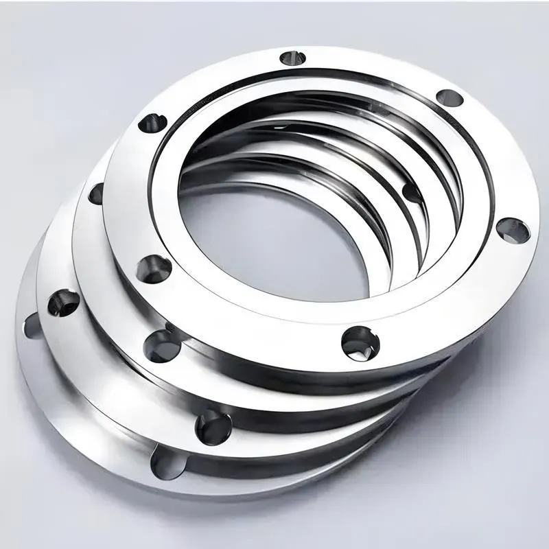
A flange—also referred to as a flange plate or rim—is a component used to connect shafts to one another, or, more commonly, to join the ends of pipes. Flanges are also utilized at the inlet and outlet ports of equipment to facilitate connections between two devices—for instance, the flange on a speed reducer. A "flange connection" or "flanged joint" refers to a detachable joint assembly comprising three interconnected elements—a flange, a gasket, and bolts—that together form a sealed structural unit. In the context of piping systems, a "pipe flange" specifically denotes a flange used for plumbing within the installation; when applied to equipment, it refers to the inlet or outlet flange of that specific device. Flanges feature a series of holes through which bolts are inserted to securely fasten the two flanges together, while a gasket placed between the flanges ensures a leak-proof seal. Flanges are broadly categorized into three types: threaded (screw-in) flanges, welded flanges, and clamp-type flanges. Flanges are invariably used in pairs; threaded flanges are suitable for low-pressure piping applications, whereas welded flanges are required for systems operating at pressures exceeding 4 kilograms per square centimeter. A sealing gasket is inserted between the two flange plates, which are then firmly secured using bolts. The thickness of a flange—as well as the specifications of the bolts used to fasten it—vary depending on the specific pressure rating required for the application. When connecting equipment such as water pumps or valves to piping systems, the corresponding connection points on these devices are often manufactured in the shape of a matching flange; this method of attachment is also referred to as a "flange connection." Generally, any connecting component that utilizes bolts to join and seal the perimeters of two flat surfaces—such as the joints in ventilation ducts—is termed a "flange"; such components may collectively be classified as "flange-type parts." However, since such a connection often constitutes merely a *portion* of a larger device—for instance, the interface between a flange and a water pump—it would be inappropriate to classify the entire water pump itself as a "flange-type part." Conversely, smaller components—such as valves—that feature such flanged interfaces may indeed be appropriately categorized as "flange-type parts."
-:-
For detailed product information, please contact sales.
-:
AISI Type A3 Tool Steel Flange Product Information
-:-
For detailed product information, please contact sales.
-:
AISI Type A3 Tool Steel Flange Synonyms
-:-
For detailed product information, please contact sales.
-:
AISI Type A3 Tool Steel Product Information
-:-
For detailed product information, please contact sales.
-:
# **Product Introduction: AISI Type A3 Tool Steel**
## **Overview**
AISI Type A3 is a **high-carbon, medium-alloy, air-hardening cold work tool steel** that represents a balanced intermediate grade between the versatile A2 and the more specialized high-wear A series steels. Characterized by its **excellent dimensional stability, good wear resistance, and improved hardness capability** compared to A2, A3 offers toolmakers a reliable material for applications requiring precise heat treatment response and consistent performance in demanding cold work environments. Its composition provides deeper hardenability than many oil-hardening grades while maintaining the distortion control advantages of air-hardening steels.
---
## **Chemical Composition (Typical Weight %)**
The composition is engineered to provide optimal carbide formation and hardenability with balanced alloy content.
| Element | Content (%) |
| :--- | :--- |
| Carbon (C) | 1.20 - 1.30 |
| Chromium (Cr) | 4.75 - 5.25 |
| Molybdenum (Mo) | 0.90 - 1.10 |
| Manganese (Mn) | 0.40 - 0.70 |
| Silicon (Si) | 0.40 - 0.60 |
| Vanadium (V) | 0.80 - 1.00 |
| Sulfur (S) | ≤ 0.03 |
| Phosphorus (P) | ≤ 0.03 |
| **Iron (Fe)** | **Balance** |
**Key Role of Elements:**
* **Higher Carbon (vs. A2):** Increases hardness potential and wear resistance through increased carbide volume.
* **Chromium & Molybdenum:** Provide excellent air-hardening characteristics, good hardenability, and contribute to wear resistance through carbide formation.
* **Higher Vanadium (vs. A2):** Enhances wear resistance through formation of hard vanadium carbides, refines grain structure, and improves toughness at high hardness levels.
* **Silicon & Manganese:** Act as deoxidizers and enhance hardenability.
---
## **Physical & Mechanical Properties**
*Note: Properties are dependent on heat treatment condition (typically hardened and tempered).*
| Property | Typical Value / Description |
| :--- | :--- |
| **Density** | 7.84 g/cm³ (0.283 lb/in³) |
| **Hardness (Annealed)** | 217 - 255 HB (Brinell) |
| **Hardness (Hardened & Tempered)** | **58 - 63 HRC** (Commonly used at 60-62 HRC, capable of higher hardness than A2) |
| **Wear Resistance** | **Very Good.** Superior to A2 due to higher carbon and vanadium content. Comparable to lower-end D2 applications. |
| **Toughness** | **Good.** Slightly lower than A2 at equivalent hardness due to higher carbon, but still offers respectable impact resistance for a wear-resistant steel. |
| **Dimensional Stability** | **Excellent.** Air-hardening characteristics provide minimal distortion (typically <0.0003 in/in) during heat treatment. |
| **Machinability (Annealed)** | **Fair** (Approx. 55-60% of 1% carbon steel). More difficult than A2 due to higher carbide content. |
| **Grindability** | **Fair to Difficult.** Requires careful technique due to hard vanadium carbides. More challenging than A2 but generally better than D2. |
| **Thermal Conductivity** | ~25.5 W/m·K at 20°C |
| **Coefficient of Thermal Expansion** | ~10.3 × 10⁻⁶/°C (20-100°C) |
---
## **Heat Treatment Guidelines**
| Process | Parameters |
| :--- | :--- |
| **Annealing** | Heat to 845-870°C (1550-1600°F), slow furnace cool at ≤22°C/hour (40°F/hour) to 480°C (900°F), then air cool. Result: 217-255 HB. |
| **Stress Relieving** | 650-680°C (1200-1255°F) for 1-2 hours, air cool. |
| **Preheating** | **Essential:** Preheat at 650-760°C (1200-1400°F) to minimize thermal stress. |
| **Austenitizing** | 955-1010°C (1750-1850°F). Typical range: 970-995°C (1775-1825°F). Higher temperatures increase hardness and wear resistance but reduce toughness. |
| **Quenching** | **Air quench** in still or forced air. For larger sections (>100mm), forced air or positive pressure quenching is recommended. |
| **Tempering** | **Must be performed immediately after quenching.** Double temper at 175-540°C (350-1000°F) for minimum 2 hours per cycle. For maximum hardness (62-63 HRC): temper at 175-205°C (350-400°F). |
---
## **Product Applications**
AISI A3 is particularly suited for applications requiring higher wear resistance than A2 while maintaining good dimensional stability.
### **Primary Applications:**
1. **Precision Gauges and Measuring Tools:** Where dimensional stability and wear resistance are critical.
2. **Forming and Blanking Dies:** For abrasive materials requiring longer tool life than A2 can provide.
3. **Punches and Piercing Tools:** For medium to high production runs on abrasive materials.
4. **Thread Rolling Dies and Forming Rolls:** Where high surface hardness and wear resistance are needed.
5. **Shear Blades and Cutting Tools:** For cutting abrasive non-metallic materials (plastics, composites, rubber).
6. **Slitter Knives and Rotary Cutters:** In paper, plastic, and light metal cutting applications.
7. **Machine Tool Components:** Wear plates, guide ways, and cam surfaces requiring hardness and stability.
### **Industry Usage:**
- **Precision Tool and Die Manufacturing**
- **Metal Stamping and Forming**
- **Plastics Processing Equipment**
- **Cutting Tool Production**
- **Gauge and Fixture Manufacturing**
---
## **International Standards & Cross-Reference**
AISI A3 has specific equivalents in several international standards.
| Standard | Designation | Equivalent / Similar Grade |
| :--- | :--- | :--- |
| **AISI/SAE (USA)** | **Type A3** | - |
| **UNS (USA)** | **T30103** | - |
| **ASTM (USA)** | A681 | Grade A3 |
| **Europe (EN)** | - | No direct common equivalent |
| **Germany (DIN)** | ~1.2365 (*approximate*) | 55NiCrMoV7 (Different composition) |
| **Japan (JIS)** | - | No direct common equivalent |
| **Sweden (SS)** | - | - |
**Note:** AISI A3 is less standardized internationally than A2 or D2. The closest functional equivalents in European standards would be modified versions of 1.2363 (X100CrMoV5-1) with higher carbon and vanadium.
---
## **Comparison with Similar Grades**
| Property | A3 vs. A2 | A3 vs. D2 |
| :--- | :--- | :--- |
| **Carbon Content** | Higher (1.20-1.30% vs. 0.95-1.05%) | Lower (1.20-1.30% vs. 1.40-1.60%) |
| **Chromium Content** | Similar | Significantly lower (5% vs. 11-13%) |
| **Vanadium Content** | Higher (0.80-1.00% vs. 0.15-0.50%) | Lower (0.80-1.00% vs. 0.70-1.20%) |
| **Maximum Hardness** | Higher (63 HRC vs. 62 HRC) | Similar (63 HRC vs. 64 HRC) |
| **Wear Resistance** | Better | Slightly lower |
| **Toughness** | Slightly lower | Better |
| **Distortion Control** | Similar (Both excellent) | Similar (Both excellent) |
---
## **Advantages & Considerations**
### **Advantages:**
1. **Higher Hardness Capability:** Can achieve 62-63 HRC vs. A2's 60-62 HRC.
2. **Improved Wear Resistance:** Better than A2 due to higher carbon and vanadium.
3. **Excellent Dimensional Stability:** Maintains precision during air hardening.
4. **Good Balance of Properties:** Between the toughness of A2 and wear resistance of D2.
5. **Reliable Heat Treatment Response:** Predictable hardening behavior.
### **Considerations:**
1. **Lower Toughness than A2:** At equivalent hardness levels.
2. **Limited International Standardization:** Less commonly available than A2 or D2.
3. **More Difficult Machining:** Higher carbide content reduces machinability.
4. **Not for Extreme Abrasion:** For severe abrasive wear, D2 or A11 may be better choices.
---
## **Availability & Processing Notes**
### **Available Forms:**
- Round Bars (¼" to 6" diameter)
- Flat Bars and Plates
- Forged Blocks
- Custom Shapes (limited availability)
### **Processing Recommendations:**
1. **Machining:** Use carbide tools, moderate speeds and feeds, adequate coolant.
2. **Grinding:** Use softer grade wheels (H-I hardness), proper coolant application.
3. **EDM:** Can be EDM machined; requires proper tempering after to relieve white layer stress.
4. **Welding:** Not generally recommended; if necessary, preheat to 300-400°C (575-750°F) and use matching analysis electrodes.
---
## **Conclusion**
AISI Type A3 tool steel occupies a valuable niche in the cold work tool steel spectrum, offering a **compromise between the excellent toughness of A2 and the superior wear resistance of D2**. Its higher carbon and vanadium content compared to A2 provides enhanced hardness capability and wear performance for applications where A2 may wear prematurely, yet where the extreme abrasion resistance of D2 is unnecessary. While less commonly specified than its A2 and D2 counterparts, A3 remains an important engineering material for precision tooling applications requiring optimal balance of properties, particularly where dimensional stability during heat treatment is paramount. Its predictable performance makes it a reliable choice for toolmakers seeking extended service life in demanding cold work applications.
-:-
For detailed product information, please contact sales.
-:
AISI Type A3 Tool Steel Specification
Dimensions
Size:
Diameter 20-1000 mm Length <6660 mm
Size:We can customized as required
Standard:
Per your request or drawing
We can customized as required
Properties(Theoretical)
Chemical Composition
-:-
For detailed product information, please contact sales.
-:
AISI Type A3 Tool Steel Properties
-:-
For detailed product information, please contact sales.
-:
Applications of AISI Type A3 Tool Steel Flange
-:-
For detailed product information, please contact sales.
-:
Chemical Identifiers AISI Type A3 Tool Steel Flange
-:-
For detailed product information, please contact sales.
-:
Packing of AISI Type A3 Tool Steel Flange
-:-
For detailed product information, please contact sales.
-:
Standard Packing:
-:-
For detailed product information, please contact sales.
-:
Typical bulk packaging includes palletized plastic 5 gallon/25 kg. pails, fiber and Steel Flange drums to 1 ton super sacks in full container (FCL) or truck load (T/L) quantities. Research and sample quantities and hygroscopic, oxidizing or other air sensitive materials may be packaged under argon or vacuum. Solutions are packaged in polypropylene, plastic or glass jars up to palletized 3131 gallon liquid totes Special package is available on request. E FORUs’ is carefully handled to minimize damage during storage and transportation and to preserve the quality of our products in their original condition