1,We Manufacturing processes are primarily classified into four types:
1:Forging,
2:Casting,
3:Cutting,
4:Rolling.
2,We can manufacture in accordance with these standards.
Standards:
GB Series (Chinese Standards), JB Series (Machinery Standards), HG Series (Chemical Industry Standards), ASME B16.5 (American Standards), BS4504 (British Standards), DIN (German Standards), and JIS (Japanese Standards).
Internationally, there are two primary systems of pipe flange standards: the European system, represented by the German DIN standards (including those of the former Soviet Union), and the American system, represented by the US ANSI pipe flange standards. Other common standards include: the Chinese Ministry of Machinery Industry standards (JB series), the Ministry of Chemical Industry standards (HG series), the Chinese National Standard *GB/T 9112–9124-2010 Steel Pipe Flanges*, as well as US standards (ASME B16.5), British standards (BS4504), German standards (DIN), Japanese standards (JIS), and marine standards (CBM), among others.
The nominal pressure ratings for the PN series are designated by "PN" and comprise the following nine levels: PN2.5, PN6, PN10, PN16, PN25, PN40, PN63, PN100, and PN160.
The nominal pressure ratings for the Class series are designated by "Class" and comprise the following six levels: Class150, Class300, Class600, Class900, Class1500, and Class2500.
Flange Classification
1. **According to Chemical Industry Standards:** Flanges are classified as follows:
Plate Flat Welding Flange (PL), Necked Flat Welding Flange (SO), Necked Butt Welding Flange (WN), Integral Flange (IF), Socket Welding Flange (SW), Threaded Flange (Th), Butt Welding Ring Loose Flange (PJ/SE), Blind Flange (BL), Flat Welding Ring Loose Flange (PJ/PJ), and Lined Blind Flange (BL(s)).
2. **According to Petrochemical (SH) Industry Standards:** Flanges are classified as follows:
Threaded Flange (PL), Butt Welding Flange (WN), Flat Welding Flange (SO), Socket Welding Flange (SW), Loose Flange (LJ), and Blind Flange (no specific designation).
3. **According to Machinery (JB) Industry Standards:** Flanges are classified as follows:
Integral Flange, Butt Welding Flange, Plate Flat Welding Flange, Butt Welding Ring Plate Loose Flange, Flat Welding Ring Plate Loose Flange, Lap Joint Ring Plate Loose Flange, and Blind Flange.
4. **According to Connection Method/Type:** Flanges are classified as follows:
Plate Flat Welding Flange, Necked Flat Welding Flange, Necked Butt Welding Flange, Socket Welding Flange, Threaded Flange, Blind Flange, Necked Butt Welding Ring Loose Flange, Flat Welding Ring Loose Flange, Ring-Type Joint (RTJ) Flange and Blind Flange, Large-Diameter Plate Flange, Large-Diameter High-Neck Flange, Figure-8 Blind Plate, Butt Welding Ring Loose Flange, etc.
5. **According to the Component Being Connected:** Flanges can be classified into Vessel Flanges and Pipe Flanges.
6. **According to Structural Type:** Flanges include Integral Flanges, Threaded Flanges, Flat Welding Flanges, Butt Welding Flanges, Lap Joint (Loose/Swivel) Flanges, and Blind Flanges.
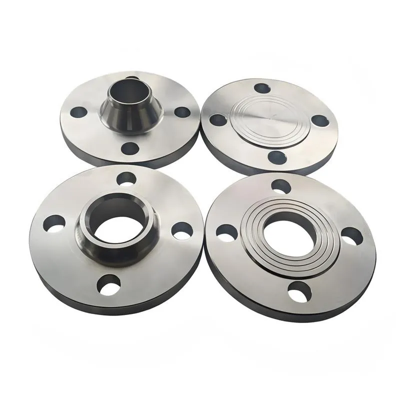
A flange—also referred to as a flange plate or rim—is a component used to connect shafts to one another, or, more commonly, to join the ends of pipes. Flanges are also utilized at the inlet and outlet ports of equipment to facilitate connections between two devices—for instance, the flange on a speed reducer. A "flange connection" or "flanged joint" refers to a detachable joint assembly comprising three interconnected elements—a flange, a gasket, and bolts—that together form a sealed structural unit. In the context of piping systems, a "pipe flange" specifically denotes a flange used for plumbing within the installation; when applied to equipment, it refers to the inlet or outlet flange of that specific device. Flanges feature a series of holes through which bolts are inserted to securely fasten the two flanges together, while a gasket placed between the flanges ensures a leak-proof seal. Flanges are broadly categorized into three types: threaded (screw-in) flanges, welded flanges, and clamp-type flanges. Flanges are invariably used in pairs; threaded flanges are suitable for low-pressure piping applications, whereas welded flanges are required for systems operating at pressures exceeding 4 kilograms per square centimeter. A sealing gasket is inserted between the two flange plates, which are then firmly secured using bolts. The thickness of a flange—as well as the specifications of the bolts used to fasten it—vary depending on the specific pressure rating required for the application. When connecting equipment such as water pumps or valves to piping systems, the corresponding connection points on these devices are often manufactured in the shape of a matching flange; this method of attachment is also referred to as a "flange connection." Generally, any connecting component that utilizes bolts to join and seal the perimeters of two flat surfaces—such as the joints in ventilation ducts—is termed a "flange"; such components may collectively be classified as "flange-type parts." However, since such a connection often constitutes merely a *portion* of a larger device—for instance, the interface between a flange and a water pump—it would be inappropriate to classify the entire water pump itself as a "flange-type part." Conversely, smaller components—such as valves—that feature such flanged interfaces may indeed be appropriately categorized as "flange-type parts."
-:-
For detailed product information, please contact sales.
-:
Ductile Iron Flange MIL-I-24137 Class A Product Information
-:-
For detailed product information, please contact sales.
-:
Ductile Iron Flange MIL-I-24137 Class A Synonyms
-:-
For detailed product information, please contact sales.
-:
Ductile Iron MIL-I-24137 Class A Product Information
-:-
For detailed product information, please contact sales.
-:
### **Product Technical Data Sheet: Ductile Iron – MIL-I-24137 Class A (Ferritic Grade)**
---
#### **1. Product Overview**
**MIL-I-24137 Class A** is a **high-ductility, ferritic ductile iron** specification established by the United States Military for demanding defense and aerospace applications. This specification has been **cancelled for new design** (as noted by the "CANCELLED" marking in the ASSIST database) but remains a relevant and specified material for legacy systems, maintenance, repair, and overhaul (MRO), and in commercial applications where its guaranteed properties are required. Class A represents the **most ductile grade** within this military standard, emphasizing **toughness, impact resistance, and pressure integrity** over raw strength. It is typically supplied in the fully annealed (ferritized) condition and is analogous to commercial grades like ASTM A536 60-40-18.
---
#### **2. Governing Standards & Specifications**
This material is defined by a rigorous military performance specification, with clear linkages to commercial standards.
* **Primary Standard: MIL-I-24137 (SUPERSEDED / CANCELLED)** - *Iron Castings, Ductile*. The active specification is **MIL-DTL-24137**, but Class A properties remain defined by the original MIL-I document. Users must verify the latest revision and status for contract purposes.
* **Cross-Equivalencies & References:**
* **ASTM A536:** **Grade 60-40-18** is the direct commercial equivalent.
* **SAE J434c:** **Grade D4018**.
* **AMS 5312C:** Aerospace Material Specification for "Ductile Iron Castings, Ferritic".
* **Federal Standard QQ-I-1104:** Superseded by MIL-I-24137 but historically related.
* **Key Testing Standards (as invoked by the MIL spec):**
* **Tensile Test:** ASTM E8
* **Hardness:** ASTM E10 (Brinell)
* **Impact Test:** ASTM E23 (Charpy)
* **Microstructure:** ASTM A247
* **Quality Assurance:** Mandatory compliance with **MIL-STD-453** for inspection and rigorous **first-article and lot testing**.
---
#### **3. Chemical Composition Requirements**
MIL-I-24137 Class A specifies chemical ranges to ensure a fully ferritic matrix and high nodularity.
| Element | MIL-I-24137 Class A Requirement (%) | Functional Rationale |
| :--- | :--- | :--- |
| **Carbon (C)** | 3.40 - 3.80 | Ensures castability and graphite formation. |
| **Silicon (Si)** | 2.20 - 2.60 | Ferritizer. Promotes the soft, ductile ferritic matrix. |
| **Manganese (Mn)** | **≤ 0.40** | Strictly limited to prevent pearlite stabilization and boundary segregation, which harms toughness. |
| **Phosphorus (P)** | **≤ 0.05** | Kept low to prevent brittle phosphide networks at grain boundaries. |
| **Sulfur (S)** | **≤ 0.02** | Kept very low to avoid interference with nodulization. |
| **Magnesium (Mg)** | Residual | Sufficient to ensure spheroidal graphite (typically 0.03-0.05%). |
| **Copper (Cu)** | **≤ 0.20** | Minimized, as it promotes pearlite, which reduces ductility. |
| **Chromium (Cr)** | **≤ 0.10** | Strictly limited as a strong carbide former. |
| **Nickel (Ni)** | Report | Not an intentional addition for this class. |
| **Other Elements** | As agreed | Trace elements controlled to prevent embrittlement. |
---
#### **4. Physical & Mechanical Properties**
The properties define a high-toughness, pressure-retaining material.
| Property | MIL-I-24137 Class A Requirement | Notes & Significance |
| :--- | :--- | :--- |
| **Tensile Strength, min.** | **414 MPa (60,000 psi)** | Base strength requirement. |
| **Yield Strength (0.2% offset), min.** | **276 MPa (40,000 psi)** | Ensures resistance to permanent deformation. |
| **Elongation, min.** | **18%** (in 2 inches) | **Key characteristic:** High ductility, critical for absorbing shock and deformation without fracture. |
| **Reduction of Area, min.** | Not typically specified in MIL-I-24137, but implied high. | Further indicator of ductility. |
| **Hardness (Brinell)** | **143 - 187 HBW** | Specified range guarantees the soft, ferritic microstructure and excellent machinability. |
| **Impact Resistance (Charpy V-Notch)** | **≥ 16 J (12 ft-lbf) @ 21°C (70°F)** | **Critical for military applications.** Guaranteed minimum toughness for shock-loaded components. |
| **Modulus of Elasticity** | ~165 - 172 GPa (Assumed) | Consistent with ferritic ductile iron. |
| **Microstructure** | **Spheroidal Graphite** (Nodularity ≥85%, Types I & II) in a **predominantly ferritic matrix** (≥90% ferrite). | The ferritic matrix is mandatory for achieving the elongation and impact properties. |
---
#### **5. Product Applications**
Originally designed for high-reliability military systems, its applications are in areas where failure due to brittle fracture is unacceptable.
* **Armored Vehicles:** **Wheel hubs, final drive housings, suspension components, and hull attachments** where mine blast or ballistic shock loads are possible.
* **Naval & Marine:** **Valve bodies, pump casings, and fittings** for shipboard piping systems requiring pressure integrity and corrosion resistance.
* **Aerospace/Ground Support:** **Landing gear components (non-primary structure), engine mounts, and hydraulic actuator bodies** for support equipment.
* **Ordnance & Weapon Systems:** **Housings, mounts, and traversing mechanisms** where shock from firing is a design factor.
* **Commercial MRO:** **Replacement parts for legacy military equipment, and in industries** (e.g., power generation, heavy machinery) that adopted this spec for its guaranteed toughness.
---
#### **6. Fabrication & Quality Assurance Notes**
* **Heat Treatment Condition:** **Annealed (Ferritized).** Castings must be heat treated to achieve the fully ferritic microstructure and meet hardness requirements.
* **Machinability:** **Excellent.** The soft ferritic matrix allows for high-speed machining, good surface finishes, and extended tool life.
* **Weldability:** **Fair, with strict procedures.** Requires pre-heat (315-650°C), use of nickel-iron electrodes (e.g., ENi-CI), and controlled post-weld cooling with stress relief. Used primarily for repair, not fabrication.
* **Military Quality Requirements:** Extremely rigorous.
* **Certification:** Foundry must provide a **Certificate of Conformance (C of C)** stating compliance with all requirements of the specification.
* **Testing:** **Separately cast test bars** (per ASTM A536 practice) from each melt are used for mechanical testing. **Impact testing is mandatory.**
* **Inspection:** Subject to **Government Source Inspection** or customer-approved quality assurance representative. **Non-Destructive Testing (NDT)** such as radiography (X-ray) or magnetic particle inspection is often invoked for critical areas.
---
#### **7. Ordering & Procurement Information**
**Specify:** **"Ductile Iron Castings, MIL-I-24137 Class A, Ferritic Annealed Condition."**
**Critical Information to Include:**
* **Reference the exact, current revision** of the specification (e.g., MIL-DTL-24137? Verify status).
* **Part Drawing & Application.**
* **Required Certifications:** C of C and full test reports (chemistry, tensile, hardness, impact, microstructure).
* **Inspection Requirements:** Source inspection requirements, any additional NDT (e.g., per NAVSEA, or drawing callouts).
* **Marking:** Requirement for casting marking with material class, foundry identification, and heat number.
**Disclaimer:** MIL-I-24137 Class A is a historical specification. For new designs, engineers are directed to use active commercial (ASTM A536) or aerospace (AMS) specifications. However, for sustainment of legacy systems, it remains a vital and precisely defined material standard.
-:-
For detailed product information, please contact sales.
-:
Ductile Iron MIL-I-24137 Class A Specification
Dimensions
Size:
Diameter 20-1000 mm Length <6528 mm
Size:We can customized as required
Standard:
Per your request or drawing
We can customized as required
Properties(Theoretical)
Chemical Composition
-:-
For detailed product information, please contact sales.
-:
Ductile Iron MIL-I-24137 Class A Properties
-:-
For detailed product information, please contact sales.
-:
Applications of Ductile Iron Flange MIL-I-24137 Class A
-:-
For detailed product information, please contact sales.
-:
Chemical Identifiers Ductile Iron Flange MIL-I-24137 Class A
-:-
For detailed product information, please contact sales.
-:
Packing of Ductile Iron Flange MIL-I-24137 Class A
-:-
For detailed product information, please contact sales.
-:
Standard Packing:
-:-
For detailed product information, please contact sales.
-:
Typical bulk packaging includes palletized plastic 5 gallon/25 kg. pails, fiber and Steel Flange drums to 1 ton super sacks in full container (FCL) or truck load (T/L) quantities. Research and sample quantities and hygroscopic, oxidizing or other air sensitive materials may be packaged under argon or vacuum. Solutions are packaged in polypropylene, plastic or glass jars up to palletized 2999 gallon liquid totes Special package is available on request. E FORUs’ is carefully handled to minimize damage during storage and transportation and to preserve the quality of our products in their original condition